Numerical simulation of fracture in plain and fibre reinforced concrete
Bạn đang xem bản rút gọn của tài liệu. Xem và tải ngay bản đầy đủ của tài liệu tại đây (9.6 MB, 312 trang )
1. INTRODUCTION 1
Chapter 1
INTRODUCTION
1.1 Background
The rapid development of fracture mechanics of quasibrittle materials in the last
three decades was essentially dictated by the realisation that its application can
lead to a satisfactory simulation and prediction of the local damage phenomena and
the effect of structural size to fracture (Baˇzant and Planas, 1998). Moreover, it
offers a logical approach to structural analysis and design based on sound mathe-
matical and mechanics concepts. Furthermore, the advent of new materials such
as high-strength concrete, fibre-reinforced concrete and polymer composites neces-
sitates the use of fracture mechanics to effectively exploit their material properties
for reasons of safety and economy. At present we are entering a period in which
the introduction of fracture mechanics into concrete design is becoming possible
(Mindess, 2002). This will help achieve more uniform safety margins, especially for
structures of different sizes. This, in turn, will improve economy as well as structural
reliability. It will make it possible to introduce new designs and utilise new concrete
materials. Applications of fracture mechanics are most urgent for structures such as
concrete dams, long span bridges, and nuclear reactor vessels or containments, for
which the safety concerns are particularly high and the consequences of potential
disaster enormous.
The applicability of fracture mechanics to real engineering problems depends
on the availability of fracture models that can simulate satisfactorily the behaviour
of quasibrittle fracture. One such model is the cohesive crack model whose early
development can be attributed to the independent works of Dugdale (1960) and
1. INTRODUCTION 2
Barenblatt (1962). The cohesive crack models were developed to simulate the non-
linear material behaviour near the crack tip. In these models, the crack is assumed
to extend and to open while still transferring stress from one face to the other. The
cohesive model proposed by Barenblatt (1959, 1962) aimed to relate the macroscopic
crack growth resistance to the atomic binding energy, while relieving the stress sin-
gularity. Barenblatt postulated that the cohesive forces were operative on only a
small region near the crack tip, and assumed that the shape of the crack profile
in this zone was independent of the body size and shape. Dugdale (1960), in an
investigation of yielding in steel sheets containing slits, formulated a model of a line
crack with a cohesive zone having constant yield stress. Although formally close
to Barenblatt’s, this model was intended to represent a completely different phys-
ical situation: macroscopic plasticity rather than microscopic atomic interactions.
Both models share a convenient picture in which the stress singularity is removed.
Despite being very simplified, Dugdale’s approach to plasticity gave a good descrip-
tion of ductile fracture for small plastic zone sizes. However, it was not intended
to describe fracture itself and, in Dugdale’s formulation, the plastic zone extended
forever without any actual crack extension. The cohesive crack model came to the
forefront in the mid 1970s with the work of Hillerborg and co-workers (Hillerborg
et al., 1976). The cohesive crack model served as a suitable nonlinear model for
mode I fracture. Their research acted as a catalyst in rousing the interest of study-
ing quasibrittle materials in fracture mechanics perspective. Since then, a number
of fracture models have been introduced and used to predict and investigate fracture
behaviour of concrete-like materials. In general, all the foregoing fracture mechanics
theories require a pre-existing crack to analyse the failure of a structure or compo-
nent. This is not so with Hillerborg’s fictitious crack model. It is a cohesive crack
in the classical sense described above, but it is more than that because it includes
crack initiation rules for any situation. This means that it can be applied to initially
uncracked concrete structures and describe all the fracture processes from no crack
at all to complete structural breakage. It provides a continuous link between the
1. INTRODUCTION 3
classical strength-based analysis of structures and the energy-based classical frac-
ture mechanics: cohesive cracks start to open as dictated by a strength criterion
that naturally and smoothly evolves towards an energetic criterion for large cracks.
Other nonlinear models such as the two-parameter model by Jenq and Shah (1985)
and effective crack model by Nallathambi and Karihaloo (1986) have also been pro-
posed. All these models use simplifying assumptions to reduce the computational
complexities inherent in fracture analysis.
The cohesive crack model defines a relationship between normal crack opening
and normal cohesive stresses, and assumes that there are neither sliding displace-
ments nor shear stresses along the process zone. This assumption is only partially
valid for concrete materials. Based on experimental observations, it is indeed cor-
rect that a crack is usually initiated in pure mode I (i.e. opening mode) in concrete,
even for mixed mode loading (Saouma, 2000). However, during crack propagation,
the crack may curve due to stress redistribution or non-proportional loading, and
significant sliding displacements develop along the crack. Therefore, it is desirable
to incorporate these shear effects. Interface elements were first proposed by Good-
man et al. (1968) to model nonlinear behavior of rock joints. Since then, numerous
interface constitutive models have been proposed for a wide range of applications
such as rock mechanics (Goodman et al., 1968), masonry structures (Lotfi, 1992)
and concrete fracture (Stankowski, 1990; Feenstra et al., 1991; Carol et al., 1992;
ˇ
Cervenka, 1994). These models are basically the extension of Hillerborg’s cohesive
crack model for shear effects, and as such it can be also used to model interface
cracks.
All fracture models are governed by a constitutive law. The cohesive crack model,
for instance, requires a tension-softening relation (softening law) to characterise the
fracture behaviour of cementitious materials. In the practical application of the
cohesive crack model, the shape of the softening law is simplified and is assumed
1. INTRODUCTION 4
f
t
w
c
w
σ
G
F
Process zone
σ
y
σ
y
Real crack
Crack opening
displacement
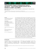
Figure 1.1: Linear softening law and the cohesive crack model
to be known a priori. Among the simplest softening relationships developed is the
linear softening law that was used by Hillerborg and co-workers (1976) to illustrate
the applicability of their proposed fracture model. As shown in Figure 1.1, only
two parameters need to be specified to sufficiently characterise the model. One
can use any of the combinations of the tensile strength f
t
and fracture energy G
F
or tensile strength f
t
and the critical crack width w
c
. Petersson (1981) proposed
the two-branch law that is generally acknowledged to provide a better approxima-
tion of the fracture behaviour of concrete. The two-branch law, in general, is fully
characterised by specifying four parameters, except if the breakpoint is known. De-
tails and the application of these models will be discussed further in the next section.
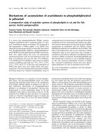
τ
σ
ϕ
c
Figure 1.2: Mohr-Coulomb criterion and shear band predicted in principal stress
space (De Borst, 1986)
Up to now, the most practical failure models that incorporate shear have been
1. INTRODUCTION 5
the Mohr-Coulomb type models, which limit and control the shear stress at a plane
as a function of the normal stress on that plane (Figure 1.2). Though they are formu-
lated in principal stress space, they actually limit the shear stress on certain planes.
Figure 1.2 shows a shear band in a specimen loaded in compression as predicted
by the use of a Mohr-Coulomb continuum model. When a shear plane is known,
it is possible to use a Mohr-Coulomb type of model for the description of interface
behaviour. Simple interface models of this type have been used by Roelfstra and
Sadouki (1986); Roelfstra (1989); Lorig and Cundall (1989); Vonk (1992). In these
models a tension cut-off criterion is added to the shear failure criterion. A more
complex model for the combination of tensile and shear loading including softening
has been proposed by Stankowski (1990).
The normality rule and/or the association of the flow laws with the yield function
in classical plasticity refer to the following circumstance: in the space of the stress
and strain components superposed, the plastic strain rate vector is normal to the
activated yield surface at the stress point. Nonassociated constitutive law refers to
circumstances otherwise (Koiter, 1960; Maier, 1969).
The safety and durability of concrete structures are significantly influenced by
the fracture behaviour of the concrete. There are many fracture formulations which
assume concrete as a homogeneous material or as a two-phase material composed
of aggregate particles dispersed in a cement paste matrix and provide reasonable
simulations. However, such models do not include the effects of the transition zone
between coarse aggregate and cement paste. It is well known that this zone has a
significant effect on the elastic properties, but little is known on how it affects the
softening process. Therefore, it is necessary to access the adequacy of fracture mod-
els considering the heterogeneous nature of concrete with three distinctive phases
(Vonk, 1992; van Mier, 1997; Leite et al., 2004).
1. INTRODUCTION 6
1.2 Aim and motivation of the research
The broad aim of the project is to develop novel methods apt to simulate fracture
behaviour and softening processes in plain and fibre-reinforced concrete as a quasi-
brittle material. Specifically, this study deals with identifying different modes of
failure, i.e. tension, shear, and compression with several questions about the in-
teraction between shear and tension. A mathematical programming based discrete
interface formulation is employed to achieve this goal. Several benchmark problems
are tackled including the compressive softening of a concrete cube and crack inter-
action in a beam.
1.3 Objective scope of study
A composite model is used to represent the heterogeneity of plain concrete consist-
ing of coarse aggregates, mortar matrix and the mortar-aggregate interface. The
composite elements of plain concrete are modelled using triangular finite element
units which have six interface nodes along their sides. Fracture is captured through
a constitutive single branch softening-fracture law at the interface nodes, which
bounds the elastic domain inside each triangular unit. The inelastic displacement
at an interface node represent the crack opening and/or sliding displacement and
is conjugate to the internodal forces. The path-dependent softening behaviour is
developed within a quasi-prescribed displacement control formulation. The crack
profile is restricted to the interface boundaries of the defined mesh. No re-meshing
is carried out. Solutions to the rate formulation are obtained using a mathematical
programming procedure in the form of a linear complementary problem. Fibre par-
ticles are modelled by introducing additional linear elements interconnecting distant
interface nodes in the matrix media after the generation of matrix-aggregate struc-
ture. The allocation of fibres is associated with the mesh structure by choosing all
possible combinations of distant nodes in the matrix which have a designated length
1. INTRODUCTION 7
range and do not cross any present aggregate particles. Limited experiments have
been undertaken on plain and fiber-reinforced concrete specimens which are used to
verify the analytical model developed.
1.4 Organisation of the research
This dissertation deals with the numerical simulation of fracture in plain concrete
and fibre reinforced concrete and is organised into nine chapters and three appen-
dices. Each chapter starts with an introduction and ends with a summary. The
introduction provides an overview, and if necessary a brief review, of the topics
contained therein. The summary highlights the important points discussed in the
chapter. Moreover, it also provides a smooth transition to the next chapter. The
contents of each chapter are briefly described in the following.
The first chapter naturally constitutes the introduction to the thesis, aims, mo-
tivation of the research and objective scope of the work. This chapter also contains
several assumptions and common notations employed throughout the thesis.
Chapter 2 comprises the literature survey of topics related to this work, i.e frac-
ture mechanics in plain and fibre reinforced concrete and the cohesive crack model.
Topics directly related to this thesis requiring more detailed discussion or derivation
are separately covered in the subsequent chapters. The literature survey provides
a brief historical overview of the early development of fracture mechanics and in-
troduces the different fracture models developed over the years starting with linear
elastic fracture mechanics (LEFM). The fundamental ideas underlying the concept
of the cohesive crack model are explained and the simplifying assumptions adopted
are discussed. The tension-softening relationship required of the model is described
and the fracture parameters characterising this softening behaviour, and their sig-
nificance to fracture mechanics, are also discussed.
1. INTRODUCTION 8
Chapter 3 deals with the formulation of the state problem expressed as a linear
complementarity problem (LCP). It covers the mathematical descriptions of basic
equations for elastic-plastic relations in structural mechanics. The concepts and
formulation of a structure into a finite number of six-node interface triangular units
each consisting of nine constant strain triangle are then presented. The implemen-
tation of a piecewise linear inelastic failure surface and softening constitutive law is
described. The single branch softening laws in tension and shear are formulated in
a complementarity format. The structural relations are cast into a nonholonomic
(irreversible) rate formulation. Also introduced in this chapter is a review of the
linear complementarity problem and its applications in engineering mechanics as
well as some of the computational algorithms employed in the thesis, such as Lemke
(Lemke, 1965) and the industry standard solver PATH (Dirkse and Ferris, 1995).
Chapter 4 discusses the methods and algorithms used in the automated mesh
generation and the composite model to include the heterogeneous nature of con-
crete (modelling at meso-level). Concrete is modelled as a three-phase material
with coarse aggregates, a mortar matrix and the mortar-aggregate interfaces. Prop-
erties of each constituent available in the literature is likewise mentioned.
Chapter 5 analyses several verification examples using actual experimental data.
One of them is the interacting crack problem. The formulation developed in Chap-
ter 3 is employed to report the investigation of multiple interacting cracks in the
four-point bending test of a simple plain concrete beam. Material properties are
assigned in a homogeneous manner. The solution algorithm concentrates on the
analysis of various fracture modes in a plain concrete beam under four point bend-
ing with several notches and examines the interacting crack itineraries by identifying
the various equilibrium solutions available. Next, two of the most cited problems in
identifying parameters of cohesive crack model in concrete, i.e. the Brazilian test
1. INTRODUCTION 9
and the three-point bending test, are numerically simulated using the same formula-
tion in conjunction with the composite model prepared in Chapter 4. The boundary
condition and factors that affect the outcome of these tests are examined.
Chapter 6 deals with an articulated particle/interface model of concrete and the
introduction of a compression cap to the Mohr-Coulomb failure surface to further
track compressive failure. As an example, results on the fracture process in a cube
of concrete under compression are studied. All major factors that affect the soft-
ening behaviour in uniaxial compression - e.g. the influence of size, the boundary
condition, etc. - are alike discussed.
Chapter 7 presents experimental results on fracture in plain and fibre-reinforced
concrete. Material tests, shear tests and three-point bending tests are in turn pre-
sented. Basically, all parameters in the particle/interface model are derived. Differ-
ent fibre dosage is used to verify how fibre content affects the fracture energy and
critical crack opening displacement of shear and beam specimens.
Chapter 8 is the further development of the presented model to include fibres.
Simulation of several tests in the literature are performed and compared with exper-
imental results. These consist of the three-point bending test and the push-off shear
test. Lastly, the experimental results obtained in this study are simulated using the
proposed model.
Chapter 9 concludes the thesis with key summaries and recommendations for
future research.
1. INTRODUCTION 10
1.5 Assumptions and notations
Where applicable, assumptions are stated immediately following the derivation and
formulation of mathematical expressions used in the thesis. The following are as-
sumed throughout:
1. The formulation is applied to quasibrittle materials.
2. Structural modes of failure are opening, shear and/or compression for concrete
constituents; tension and/or pullout failure for steel fibres.
3. Linear softening laws are employed for all modes of fracture.
4. Displacements are assumed to be small. The loading path is piecewise lin-
earised (i.e., any given nonlinear load path is divided into a finite number of
proportional loading stages).
The following conventions are used for general description throughout the thesis
while specific ones are indicated where appropriate.
1. Vectors and matrices are indicated by bold type symbols. Column vectors are
assumed throughout.
2. A scalar quantity is denoted in italics.
3. A real vector a of size n is indicated by a ∈ R
n
and a real m ×n matrix A by
A ∈ R
m×n
. 0 denotes a null vector.
4. Transpose of a vector or a matrix is indicated by the superscript T; the inverse
of a matrix by the superscript -1.
5. The complementarity relationship between two nonnegative vectors f and z is
written as f
T
z = 0 which implies the componentwise condition of f
k
z
k
= 0 for
all k. Vector inequalities apply componentwise.
1. INTRODUCTION 11
1.6 Abbreviations
The following will list some common abbreviations that are valid throughout the
thesis, however many less common will be defined on a chapter by chapter basis.
CMOD = Crack Mouth Opening Displacement
LEFM = Linear Elastic Fracture Mechanics
LVDT = Linear Variable Displacement Transducer
LCP = Linear Complementarity Problem
FRC = Fibre Reinforced Concrete
SFRC = Steel Fibre Reinforced Concrete
NSC = Normal Strength Concrete
HSC = High Strength Concrete
TPB = Three-Point Bending
FEM = Finite Element Method
BEM = Boundary Element Method
2. PRELIMINARIES AND LITERATURE REVIEW 12
Chapter 2
PRELIMINARIES AND LITERATURE
REVIEW
2.1 Introduction
The cohesive crack model (Hillerborg et al., 1976) is undoubtedly one of the most
widely used nonlinear fracture models for quasibrittle materials to date. Its pop-
ularity stems from its conceptual simplicity coupled with its proven capability to
predict and simulate fracture processes satisfactorily. Moreover, the model can be
implemented quite easily using such numerical analysis tools as the finite element
method (FEM), the boundary element method (BEM) and/or other discrete crack
models. Numerous papers have been written regarding its application on fracture
problems, and in many instances the model has been used as a yardstick for other
fracture models.
This section gives an introduction to fracture mechanics in general and deals with
the cohesive crack model in particular. In the next section, a brief historical review
of the evolution of fracture mechanics is given which provides an insight into why
early attempts to use classical fracture methods failed to predict the behaviour of
concrete and concrete-like materials. The review then leads to a discussion of various
fracture models, which were inspired by the introduction of the cohesive crack model.
The development of the cohesive crack model, as formulated by Hillerborg et al.
(1976), is discussed at length in Section 2.3. The different assumptions used in the
model are explained. The formation and localisation of the fracture process zone
and its idealisation in the model are described. Essential features and limitations
2. PRELIMINARIES AND LITERATURE REVIEW 13
of the model are elaborated. The relation of the cohesive crack model with other
proposed fracture models is likewise discussed.
The next four sections of this chapter will review various fracture mechanics
approaches to quasibrittle materials. The last part mentions the history of fiber
reinforced concrete (FRC) and the modelling of its behaviour in light of fracture
mechanics.
2.2 A review of fracture mechanics and quasibrit-
tle models
The advent of fracture mechanics is generally attributed to the pioneering work of
Inglis (1913) when he observed that stresses at the vertex of a degenerate ellipsoidal
cavity tended to infinity. Consequent studies by other researchers have, since then,
led to a better and deeper understanding of fracture phenomena. This in turn has
resulted in the development of theories to explain and quantify the observed physical
behaviour of a structure in fracture.
Among the earliest fracture theory developed was linear elastic fracture mechan-
ics (LEFM). Its early development can be traced back to the work of Alan Griffith,
a British aeronautical engineer, when he formulated an energy equation to describe
the propagation of slit-like cracks using the concept of critical energy release rate
G
c
(Griffith, 1920). The theory began from a hypothesis that brittle materials con-
tain elliptical microcracks, which introduce high stress concentrations near their
tips. This fracture criterion, which is essentially a statement of the energy balance
principle, states that crack propagation initiates when the gain in surface energy
due to the increase in surface area equals the reduction in strain energy due to the
displacement of the boundaries and the change in the stored elastic energy.
2. PRELIMINARIES AND LITERATURE REVIEW 14
Griffith’s fracture theory, however, is applicable only to the failure analysis of
elastic homogeneous brittle materials such as glass and brittle ceramics. Realis-
ing this limitation, Orowan (1949) and Irwin (1957) proposed a modification of the
theory, which can be used for engineering materials exhibiting limited ductility. A
flat line crack which presents two singularities at its extremes was introduced to
consider the friction developing between crack surfaces. The model is an extension
of the energy formulation used by Griffith where the plastic strain energy rate for
crack propagation was added to the energy equation. Both researchers recognised
that the energy required to produce plastic strain at the crack tip is much greater
than the surface energy needed to create new crack surfaces. It is through this work
of Orowan (1949) and Irwin (1957) that LEFM was formally developed.
Irwin (1957) formulated a novel approach where the concept of the critical stress
intensity factor K
Ic
is used as a criterion for crack extension; the subscript ”
I
” refers
to mode I fracture or pure opening. The critical stress intensity factor K
Ic
is called
fracture toughness and it is a measure of the resistance of a material to fracture.
Known as the Irwin’s criterion, the formulation is appealing due to its proximity to
conventional stress analysis. Moreover, its application to linear elasticity allows the
stress intensity factor K
I
to be additive. Irwin (1957) also derived a relationship
that exists between the stress intensity factor K
I
and Griffith’s energy release rate
G
I
given by:
G
I
=
K
2
I
E
∗
(2.1)
where E
∗
= E for plane stress and E
∗
=
E
1 − ν
2
for plane strain. E and ν are
Young’s modulus and Poisson’s ratio, respectively.
Interest in the fracture mechanics of ductile materials arose out of the research
conducted by Dugdale (1960) and Barenblatt (1962). Dugdale proposed a simple
2. PRELIMINARIES AND LITERATURE REVIEW 15
model, the strip-yield model, to deal with plasticity at the crack tip. A key assump-
tion in the model states that the stress values at the crack tip are limited by the
yield strength of the material and that yielding is confined to a narrow band along
the crack line. Although mathematically similar to Dugdale’s model, Barenblatt’s
work, nonetheless, is conceptually different since it deals with the cohesive zone at a
molecular level instead of macroscopic plasticity. The independent work of Dugdale
and Barenblatt served as the foundation in the formulation of the cohesive crack
model.
Another notable contribution on elastoplastic fracture mechanics was the intro-
duction of the path independent integral known as the J -integral by Rice (1968).
By idealising plastic deformation within the deformation theory of plasticity, Rice
was able to show that the energy release rate G is equivalent to the J -integral. It
is worth noting that the path independence of the J-integral holds only for elastic
materials where unloading follows the path of loading.
In the 1960s, a study on the fracture behaviour of concrete using LEFM was
gaining interest. Attempts by researchers, such as Kaplan (1961), to apply the prin-
ciples of LEFM to specimen-size concrete were unfruitful. It was observed that the
predicted results obtained from theory differ significantly from experimental results.
The reason for the discrepancy, which is essentially due to the microcracking of the
tensile response of concrete-like materials, is now common knowledge. A study made
by Kesler et al. (1972) shows conclusively that LEFM of sharp cracks was inade-
quate for normal concrete structures. This conclusion was supported by the results
of Walsh (1972), who tested geometrically similar notched beams of different sizes
and plotted the results in a double logarithmic diagram of nominal strength versus
size. Without attempting a mathematical description, he made the point that this
diagram deviates from a straight line of slope −
1
2
predicted by LEFM.
2. PRELIMINARIES AND LITERATURE REVIEW 16
softening
Nonlinear
zone
softening
softening
Nonlinear
z
one
Nonlinear
z
one
(a) Brittle material (b) Ductile material (c) Quasibrittle material
l
inear
elastic
l
inear
elastic
l
inear
elastic
σ
σ
σ
Figure 2.1: Relative sizes of the fracture process zone (Baˇzant, 1985). Diagrams at
the top show the trends of the stress distribution along the crack line
The use of LEFM to model concrete fracture was borne out of ignorance of the
material’s property at that time. Concrete was then thought to be a brittle material.
It was later realised that the material exhibits decreasing tensile carrying capacity
with increasing deformation after the peak stress is reached. This response is known
as tension softening, and materials exhibiting such response are called quasibrittle
materials. For quasibrittle materials, the physical processes occurring ahead of the
crack tip are quite different from those of brittle and ductile materials. Figure 2.1
shows a comparison of the relative sizes of the process zones occurring in the three
types of materials mentioned.
The original formulation of LEFM by Griffith (1920) and Irwin (1957) is appli-
cable only to materials where the size of the nonlinear region ahead of the crack tip
is negligible. Brittle materials (Figure 2.1) fall into this category where the state
of stress ahead of the crack tip can be described by a single parameter singularity
such as the critical values of the energy release rate G
Ic
or the stress intensity factor
K
Ic
. For quasibrittle materials such as concrete, Figure 2.1 clearly shows the inap-
plicability of LEFM due to the long length of the fracture process zone relative to
the dimension of the specimen. It is evident then that a single fracture parameter
criterion will not be sufficient to fully describe the complex behaviour of the fracture
process zone.
2. PRELIMINARIES AND LITERATURE REVIEW 17
For large structures, however, LEFM can be used as a valid fracture model pro-
vided a crack-like notch or flaw exists in the structure. The applicability of the
theory lies in the relative size of the fracture process zone compared to the dimen-
sion of the structure, i.e., when the length of the process zone is negligible relative to
the size of a large structure. In such cases, the nonlinear region can be lumped into
a single point and a single parameter fracture criterion is sufficient to describe the
fracture processes. Studies have shown that the value of the critical stress intensity
factor K
Ic
, a parameter used in LEFM, reaches a constant value for large structures.
A number of papers have been published on the use of LEFM for the analysis of
large structures. For instance, Saouma and Morris (1998) successfully used LEFM
theory in the safety evaluation of a concrete dam.
Hillerborg and co-workers (Hillerborg et al., 1976) were the first to introduce
a nonlinear fracture model for quasibrittle materials. Based on the idea of plas-
tic crack-tip zone espoused by Dugdale (1960) and Barenblatt (1959), Hillerborg
proposed the cohesive crack model for analysing the physical behaviour of concrete
in fracture. Unlike LEFM-based models where their applicability depends on the
prior existence of notch-like cracks, the cohesive crack model can be used to describe
the behaviour of uncracked as well as cracked quasibrittle structures. An essential
ingredient of the proposed fracture model for analysis is the softening law. For a
generic nonlinear softening law with the shape function σ = f (w) given (see Figure
2.2), the essential parameters include the tensile strength f
t
and fracture energy
G
F
. The fracture energy G
F
is defined as the area under the stress-displacement
discontinuity (σ −w) curve, where σ is the tensile stress and w is the crack mouth
opening displacement. A detailed discussion of the cohesive crack model is taken up
in the next section and topics relevant to the model are discussed therein.
The introduction of the cohesive crack model as a suitable fracture mechanics
2. PRELIMINARIES AND LITERATURE REVIEW 18
f
t
w
c
w
σ
G
F
Figure 2.2: A generic nonlinear softening curve for cohesive crack model
model for concrete has ignited the interests of researchers working in fracture me-
chanics of quasibrittle materials. The last twenty years is characterised by a rapid
development of the theory and experimental techniques employed in the investiga-
tion of such fracture processes. Within that period, numerous models have been
developed and proposed as suitable fracture mechanics tools for the analysis of qua-
sibrittle fracture.
Inspired by the success of the cohesive crack model, Baˇzant and Oh (1983) pro-
posed the crack-band model. Also based on the concept of representing material
damage by a cohesive zone, the formulation of the crack band model has some
similarities to that of the cohesive crack model. However, instead of idealising the
fracture process zone as a line crack, the crack band model assumes that the fracture
process zone forms within a band of finite width h
c
. The width h
c
of this band is
considered a constant. A uniform distribution of microcracks is also assumed within
this band.
In the crack band model, a stress-strain curve is used to describe the material
behaviour at the fracture process zone. The energy consumed in the formation and
opening of all the microcracks per unit area is known as the fracture energy G
f
.
For a piecewise linear stress-strain curve as shown in Figure 2.3, the fracture energy
2. PRELIMINARIES AND LITERATURE REVIEW 19
σ
f
t
ε
E
G
f
E
t
1
1
h
c
Figure 2.3: Piecewise linear stress-strain curve for the crack band model
G
f
is evaluated as the product of the crack band width h
c
and the area under the
stress-strain diagram given as:
G
f
=
f
2
t
2
1
E
−
1
E
t
h
c
(2.2)
where E is Young’s modulus of elasticity and E
t
is the tangent strain-softening mod-
ulus. The parameters f
t
, E, E
t
and h
c
are considered material properties. These
are the parameters required for use of the crack band model.
Two inherent limitations of the crack band model are noted: (a) The assump-
tions of constant band width and uniform distribution of strain within the band
width appear to have no direct experimental evidence. The value of the band width
h
c
equal to 3d
max
, where d
max
is the largest aggregate size used in the concrete mix,
as suggested by Baˇzant, was indirectly determined by inverse analysis; (b) Numeri-
cal predictions show that the behaviour of the structure is essentially insensitive to
the band width within certain limits.
The numerical implementation of most nonlinear models for fracture analysis is
quite computationally involved. However, if only the maximum load and not the
complete softening behaviour of the structure is required, approximate models may
suffice. These models use the fracture criterion employed in LEFM. Whereas, clas-
sical LEFM requires only one fracture criterion, most approximate models use two
2. PRELIMINARIES AND LITERATURE REVIEW 20
parameters to describe the process zone. Among the more popularly known include
Jeng and Shah’s two-parameter model (Jenq and Shah, 1985) and the effective crack
model by Nallathambi and Karihaloo (1986). These models are often referred to as
the equivalent elastic crack model where a real structure is replaced by an equivalent
elastic structure. As a consequence, computations are simplified since only linear,
instead of nonlinear, analysis is required.
a
o
a
e
P
CMOD
CTOD = CTOD
c
a
o
a
e
notch
K
I
= K
Ic
d
s
Figure 2.4: Definition of the two-parameter fracture model (Jenq and Shah, 1985)
In the original formulation of the two-parameter model (Jenq and Shah, 1985),
only the conditions for peak load are given. The model assumes that at peak load
the stress intensity factor K
I
and crack tip opening displacement (CTOD) reach
critical values and the following relations hold:
K
I
= K
s
Ic
CTOD = CTOD
c
(2.3)
where K
s
Ic
and CTOD
c
are the critical values of the stress intensity factor and crack
tip opening displacement, respectively. A graphical representation of the model is
shown in Figure 2.4. Evidently, as Figure 2.4 illustrates, the critical value of the
stress intensity factor K
s
Ic
is determined at the tip of the effective crack length a
e
using the LEFM formula:
K
s
Ic
= σ
c
√
πa
e
g
1
a
e
d
(2.4)
in which, σ
c
is the stress at peak load; g
1
is a function of the geometry of a specimen;
and d is the specimen height. Diagrammatically, K
s
Ic
is measured at the tip of the
2. PRELIMINARIES AND LITERATURE REVIEW 21
effective crack length a
e
, CTOD
c
is determined at the notch (or real crack) tip. The
effective crack length a
e
is obtained from the unloading compliance measured at the
peak load.
The model parameters K
s
Ic
and CTOD
c
are considered material constants, i.e.,
the values are independent of specimen geometry and loading arrangements. These
parameters can be measured directly using three-point bending tests of a notched
specimen. It is not easy however to obtain accurate measurements of these param-
eters.
A conceptually similar approach to the two-parameter model is the effective
crack model proposed by Nallathambi and Karihaloo (1986). However, a secant
compliance at peak load is used in the determination of the effective crack length
a
e
. Moreover, the key parameters which indicate the onset of fracture are K
e
Ic
and
the effective crack length a
e
. The model assumes that the critical fracture state is
reached when stress intensity factor K
I
corresponding to the effective crack length
a
e
takes the critical value K
e
Ic
.
Another widely used adaptation of LEFM for quasibrittle fracture is the size
effect law by Baˇzant (1984). Using dimensional analysis and similitude, Baˇzant
proposed a scaling law that can predict the value of the failure stress using notched
geometrically similar structures. The equation for the scaling law is expressed as:
σ
c
=
Bf
t
1+
d
d
0
1/2
(2.5)
where σ
c
is the nominal stress at peak load, B and d
o
are empirical constants which
can be determined (by optimisation) using experimental data obtained from a num-
ber of geometrically similar notched beam specimens of different sizes. B and d
o
are
related to the size effect model parameters G
f
and c
f
where the latter is defined as
2. PRELIMINARIES AND LITERATURE REVIEW 22
Nonlinear fracture
mechanics
Limit
analysis
LEFM
2
1
log (d)
log (
c
)
Figure 2.5: Size effect law as defined in Equation (2.5) after Baˇzant (1984)
the critical crack extension for infinite sizes. A definition of Baˇzant’s size effect law
is graphically illustrated in Figure 2.5.
It is worth mentioning that the two-parameter model, the effective crack model
as well as the size effect model are predictive models. Since the required parameters
are defined at the critical state, these models can only predict the peak load and the
corresponding displacement of the structure. As it is, the models cannot describe
the softening response of the structure beyond the peak load. A generalisation of
the models to allow full analysis of the fracture processes can be achieved through
the use of R-curves (Karihaloo, 1995).
A multi-fractal scaling law capable of extrapolating results from laboratory size
specimens to actual structural size was proposed by Carpinteri and Ferro (1994)
and Carpinteri et al. (1997). To quantify the degree of disorder present in the
microstructures of quasibrittle materials, fractal geometry was used instead of the
typical integer topological dimensions of Euclidean sets.
There are other fracture models that were developed for quasibrittle fracture.
Among these include local and nonlocal continuum damaged mechanics models, lat-
tice models, stochastic methods, among many others. Excellent monographs written
2. PRELIMINARIES AND LITERATURE REVIEW 23
σ
y
σ
y
Real crack
Plastic zone
Crack opening
displacement
Figure 2.6: Dugdale’s plastic zone model
by Karihaloo (1995), Baˇzant and Planas (1998), Shah et al. (1995) and van Mier
(1997) provide comprehensive discussions on these models.
2.3 A review of the cohesive crack model
The concept of using a cohesive zone to model stress behaviour near the crack tip
was pioneered by Dugdale (1960) and Barenblatt (1962). In Dugdale’s model (Fig-
ure 2.6), it is assumed that a stress, equal to the yield value of the material, acts
uniformly across the cohesive zone. Barenblatt’s model, which is mathematically
similar to Dugdale’s model, assumes that the stress varies across the cohesive zone
as a function of the cohesive crack width.
The application of cohesive zones to study fracture nucleation and crack prop-
agation in concrete was first explored by Hillerborg and co-workers (1976). The
developed model, which they implemented within a FEM to study the fracture be-
haviour of an unreinforced beam in bending, was called the fictitious crack model
(Hillerborg et al., 1976; Petersson, 1981). However, more recently, its semblance
with the cohesive model proposed by Barenblatt led many researchers to call it with
the former terminology of ”cohesive crack model” (Carpinteri et al., 2003; Carpin-
teri, 1989), and the model has been used with this name by a number of researchers
(for instances, Carpinteri and Valente (1988); Cen and Maier (1992); Elices et al.
2. PRELIMINARIES AND LITERATURE REVIEW 24
(2002), among others). From this point forward, the term ”cohesive crack model”
might be used to refer to the fictitious crack model as formulated by Hillerborg et al.
(1976) and Petersson (1981).
Hillerborg’s cohesive crack model is conceptually simple, and it is simple enough
to be understood even by someone who has little knowledge of fracture mechan-
ics. This is no doubt one reason for its popularity (Baˇzant, 2002). Yet it provides
an excellent description of the fracture processes in quasibrittle structures. Unlike
LEFM models which can be applied only to initially cracked structures, the cohesive
crack model can capture the behaviour of a structure from crack initiation to fail-
ure. Although the model was developed for mode I fracture (tension failure), it has
nevertheless wide ranging application in fracture problems since tension failure is
by far the most dominant mode of failure in quasibrittle structures. Recently, some
researchers have attempted to extend the concept to mixed mode I and II situations
(Carpinteri, 1989; Hassanzadeh and Hillerborg, 1989).
σ
f
t
δ
A
D
C
B
w
x
1
Figure 2.7: Stress-deformation behaviour of a quasibrittle specimen in tension
The fundamental idea of the cohesive crack model is best described from a study
of the stress-deformation diagrams obtained from a simple tension test (Figure 2.7).
Displacement control, which is monotonically increasing in time, is assumed in the
test to ensure stable crack propagation. Moreover, since the level of analysis is
2. PRELIMINARIES AND LITERATURE REVIEW 25
macroscopic, the specimen can be assumed homogeneous. This illustration high-
lights many of the assumptions used in defining the cohesive crack model.
The figure shows two curves, ABC and ABD. These curves represent the stress-
deformation behaviour at two different locations of the tension test specimen. ABC
describes the behaviour at location x
1
where a localised fracture zone (fracture pro-
cess zone) develops. ABD, on the other hand, is a representative behaviour of the
material at a location other than the fracture process zone.
The fact that both curves have the same ascending branch A indicates that prior
to the attainment of the peak stress (tensile strength) f
t
the whole specimen is sub-
jected to the same stress and deformation. Therefore, a stress-strain (σ −ε) law can
be used to describe the material behaviour at this stage. For concrete (and other
cementitious materials) under tension, segment A deviates very little from a straight
line. It is not surprising then that in most applications, a linear stress-strain relation
is assumed.
Right after the tensile strength f
t
of the material is reached, the fracture process
zone is assumed to develop at location x
1
. Its formation is essentially due to mi-
crocracking which ”softens” the material at this location. The stress-displacement
discontinuity (σ − w) relation which describes the material behaviour in this zone
is known as the tension-softening relation, or simply softening relation. As segment
C of Figure 2.7 shows, the softening relation is characterised by a decreasing stress
with increasing deformation.
Any increase in the deformation of the specimen at this stage is localised within
the fracture process zone. In fact, as the deformation increases, the more localised
the damage zone becomes. As a consequence, outside the process zone, the whole
specimen can still be described by a stress-strain (σ − ε) relation. At the damaged