HỆ THỐNG SƯỞI, ĐIỀU HÒA VÀ THÔNG GIÓ TRANG 1-20 TRÊN XE MATIZ ĐỜI 2000-2013
Bạn đang xem bản rút gọn của tài liệu. Xem và tải ngay bản đầy đủ của tài liệu tại đây (466.25 KB, 20 trang )
DAEWOO M-150 BL2
SECTION 7B
MANUAL CONTROL HEATING, VENTILATION,
AND AIR CONDITIONING SYSTEM
CAUTION: Disconnect the negative battery cable before removing or installing any electrical unit or when a
tool or equipment could easily come in contact with exposed electrical terminals. Disconnecting this cable
will help prevent personal injury and damage to the vehicle. The ignition must also be in B unless otherwise
noted.
TABLE OF CONTENTS
Description and Operation 7B-2. . . . . . . . . . . . . . . . . .
System Components – Functional 7B-2. . . . . . . . . . .
Component Locator 7B-3. . . . . . . . . . . . . . . . . . . . . . . .
A/C System 7B-3. . . . . . . . . . . . . . . . . . . . . . . . . . . . . .
Diagnostic Information and Procedures 7B-5. . . . .
General Diagnosis 7B-5. . . . . . . . . . . . . . . . . . . . . . . . . . .
Testing the Refrigerant System 7B-5. . . . . . . . . . . . . .
Insufficient Cooling “Quick Check”
Procedure 7B-5. . . . . . . . . . . . . . . . . . . . . . . . . . . . . .
Pressure-Temperature Relationship
of R-134a 7B-6. . . . . . . . . . . . . . . . . . . . . . . . . . . . . .
Leak Testing the Refrigerant System 7B-7. . . . . . . . .
Air Conditioning System Diagnosis 7B-8. . . . . . . . . . . . .
Insufficient Cooling Diagnosis 7B-8. . . . . . . . . . . . . . .
Symptom Diagnosis 7B-11. . . . . . . . . . . . . . . . . . . . . . . .
Pressure Test Chart (R-134a System) 7B-11. . . . . . .
Repair Instructions 7B-13. . . . . . . . . . . . . . . . . . . . . . . .
On-Vehicle Service 7B-13. . . . . . . . . . . . . . . . . . . . . . . . .
General A/C System Service Procedures 7B-13. . . . . .
O-Ring Replacement 7B-13. . . . . . . . . . . . . . . . . . . . .
Handling Refrigerant 7B-13. . . . . . . . . . . . . . . . . . . . . .
Handling of Refrigerant Lines and Fittings 7B-13. . .
Maintaining Chemical Stability in the
Refrigeration System 7B-14. . . . . . . . . . . . . . . . . . .
Discharging, Adding Oil, Evacuating, and
Charging Procedures for A/C System 7B-14. . . . .
Serviceable Components 7B-17. . . . . . . . . . . . . . . . . . . .
Control Assembly and Control Cables 7B-17. . . . . . .
Blower Motor and Cooling Hose 7B-17. . . . . . . . . . . .
Blower Resistor 7B-17. . . . . . . . . . . . . . . . . . . . . . . . . .
Blower Motor Switch 7B-17. . . . . . . . . . . . . . . . . . . . . .
A/C Push Knob 7B-18. . . . . . . . . . . . . . . . . . . . . . . . . .
Receiver–Dryer and Dual Cut Switch 7B-18. . . . . . . .
Receiver–Dryer Bracket 7B-20. . . . . . . . . . . . . . . . . . .
Compressor 7B-20. . . . . . . . . . . . . . . . . . . . . . . . . . . . .
Condenser 7B-21. . . . . . . . . . . . . . . . . . . . . . . . . . . . . .
A/C High Pressure Pipe Line 7B-22. . . . . . . . . . . . . . .
A/C Low Pressure Pipe Line 7B-25. . . . . . . . . . . . . . .
Evaporator Unit and Drain Hose 7B-26. . . . . . . . . . . .
Unit Repair 7B-28. . . . . . . . . . . . . . . . . . . . . . . . . . . . . . . .
Evaporator Core and Expansion Valve 7B-28. . . . . .
Compressor Overhaul 7B-29. . . . . . . . . . . . . . . . . . . . .
Specifications 7B-30. . . . . . . . . . . . . . . . . . . . . . . . . . . .
General Specifications 7B-30. . . . . . . . . . . . . . . . . . . .
Fastener Tightening Specifications 7B-30. . . . . . . . . .
Special Tools and Equipment 7B-31. . . . . . . . . . . . . .
Special Tools Table 7B-31. . . . . . . . . . . . . . . . . . . . . . .
Schematic and Routing Diagrams 7B-32. . . . . . . . . .
A/C Diagrams 7B-32. . . . . . . . . . . . . . . . . . . . . . . . . . . .
A/C Airflow (Typical) 7B-33. . . . . . . . . . . . . . . . . . . . . .
A/C System (Typical) 7B-33. . . . . . . . . . . . . . . . . . . . .
7B–2 MANUAL CONTROL HEATING, VENTILATION, AND AIR CONDITIONING SYSTEM
DAEWOO M-150 BL2
DESCRIPTION AND OPERATION
SYSTEM COMPONENTS
–FUNCTIONAL
Compressor
All compressors are belt–driven from the engine crank-
shaft through the compressor clutch pulley. The com-
pressor pulley rotates without driving the compressor
shaft until on electromagnetic clutch coils energized.
When voltage is applied to energize the clutch coil, the
clutch plate and hub assembly are drawn toward the
pulley. The magnetic force locks the clutch plate and
pulley together as one unit to drive the compressor
shaft.
Condenser Core
The condenser assembly in front of the radiator consists
of coils which carry the refrigerant and cooling fins that
provide the rapid transfer of heat. The air passing
through the condenser cools the high–pressure refriger-
ant vapor and cause it to condense into a liquid.
Expansion Valve
The expansion valve is located on the passenger
compartment side of the dash panel. The expansion
valve can fail in three different positions: open, closed,
or restricted. An expansion valve that fails in the open
position will result in a noisy A/C compressor or no cool-
ing. The cause can be a broken spring, a broken ball, or
excessive moisture in the A/C system. If the spring or
the ball is found to be detective, replace the expansion
valve. If excessive moisture is found in the A/C system,
recycle the refrigerant. An expansion valve that fails in
the closed position will result in low suction pressure and
no cooling. This may be caused by a failed power done
or excessive moisture in the A/C system. If the power
dome on the expansion valve is found to be defective,
replace the expansion valve. If excessive moisture is
found in the A/C system, recycle the refrigerant.
A restricted expansion valve will result in low suction
pressure and no cooling. This may be caused by debris
in the refrigerant system. If debris is believed to be
cause, recycle the refrigerant, replace the expansion
valve, and replace the receiver/dryer.
Evaporator Core
The evaporator is device which cools and dehumidifies
the air before it enters the vehicle. High–pressure liquid
refrigerant flows through the expansion tube (orifice)
and becomes a low–pressure gas in the evaporator. The
heat in the air passing through the evaporator core is
transferred to the cooler surface of the core, which cools
the air. As the process of heat transfer from the air to the
evaporator core surface is taking place, any moisture
(humidity) in the air condenses on the outside surface of
the evaporator core and is drained off as water.
Receiver–Dryer
The sealed receiver–dryer assembly is connected to the
evaporator outlet pipe. It acts as a refrigerant storing
container, receiving liquid and some vapor and refriger-
ant oil from the evaporator.
At the bottom the receiver–dryer is the desiccant, which
acts as a drying agent for the moisture that may have
entered the system. The receiver–dryer is serviceable
only as an assembly.
Dual Cut Switch
The dual cut switch controls compressor operation when
the cycling refrigerant pressure is dropped or surged.
Evaporator Thermistor
A semiconductor which resistance is noticeably changed
as the change of temperature. When the refrigerant tem-
perature of the evaporator drops to 0_C (32_F) and be-
low, the evaporator cores get stuck with frost or ice,
reducing the airflow, lowering the cooling capacity. The
thermistor is a sensor which is used to prevent from frost-
ing or icing.
The thermistor is installed on the evaporator.
MANUAL CONTROL HEATING, VENTILATION, AND AIR CONDITIONING SYSTEM 7B – 3
DAEWOO M-150 BL2
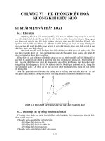
COMPONENT LOCATOR
A/C SYSTEM
(Left–Hand Drive Shown, Right–Hand Drive Similar)
D18B401B
7B–4 MANUAL CONTROL HEATING, VENTILATION, AND AIR CONDITIONING SYSTEM
DAEWOO M-150 BL2
1. High Pressure Pipe
(Receiver Dryer → Evaporator)
2. Low Pressure Hose
(Evaporator → Compressor)
3. O–ring
4. Evaporator Module
5. Evaporator Upper Case
6. thermistor
7. Evaporator Core
8. Expansion Valve
9. Evaporator Inlet Pipe
10. Plate
11. Evaporator Lower Case
12. O–ring
13. High Pressure Pipe
(Compressor → Condenser)
14. Compressor
15. Compressor Magnetic Clutch
16. Compressor Pulley
17. Compressor Clutch Drive
18. Shaft Bolt
19. High Pressure Pipe
(Condenser → Receiver–Dryer)
20. Condenser
21. Receiver–Dryer
22. Dual Cut Switch
23. Receiver–Dryer Bracket
24. Compressor Bracket
25. Compressor Stay
26. A/C & Power Steering Bracket
MANUAL CONTROL HEATING, VENTILATION, AND AIR CONDITIONING SYSTEM 7B – 5
DAEWOO M-150 BL2
DIAGNOSTIC INFORMATION AND PROCEDURES
GENERAL DIAGNOSIS
TESTING THE REFRIGERANT
SYSTEM
If you suspect a problem in the refrigerant system,
check for the following conditions:
1. Check the outer surfaces of the radiator and the con-
denser cores to be sure that the airflow is not blocked
by dirt, leaves, or other foreign material. Check be-
tween the condenser and the radiator, as well as all
outer surfaces.
2. Check for restrictions or kinks in the condenser core,
the hoses, and the tubes.
3. Check the operation of the blower fan.
4. Check all the air ducts for leaks or restrictions. A low
airflow rate may indicate a restricted evaporator core.
5. Check for slippage of the compressor clutch.
6. Check the drive belt tension.
INSUFFICIENT COOLING “QUICK
CHECK” PROCEDURE
Perform the following “hand-feel” procedure to get a
quick idea of whether the air conditioning (A/C) system
has the proper charge of Refrigerant-134a.
1. Warm up the engine. Run the engine at idle.
2. Open the hood and all the doors.
3. Turn the A/C switch ON.
4. Set the temperature control to the full cold position.
5. Set the blower speed switch on 4.
6. “Hand-feel” the temperature of the evaporator outlet
pipe. The pipe should be cold.
7. Check for other problems. Refer to “Testing the Re-
frigerant System” in this section.
8. Leak check the system. Refer to “Leak Testing the
Refrigerant System” in this section. If you find a leak,
discharge the system and repair the leak as required.
After completing the repair, evacuate and charge the
system.
9. If there is no leak, refer to “Insufficient Cooling Diag-
nosis” in this section.
7B–6 MANUAL CONTROL HEATING, VENTILATION, AND AIR CONDITIONING SYSTEM
DAEWOO M-150 BL2
PRESSURE-TEMPERATURE RELATIONSHIP OF R-134A
TEMPERATURE
_C (_F)*
PRESSURE
kPa (psig)*
TEMPERATURE
_C (_F)*
PRESSURE
kPa (psig)*
–8.89 (16) 105.70 (15.33) 37.78 (100) 856.84 (124.27)
–7.78 (18) 114.87 (16.66) 38.89 (102) 886.56 (128.58)
–6.67 (20) 124.32 (18.03) 40.00 (104) 916.35 (132.98)
–5.56 (22) 134.11 (19.45) 41.11 (106) 947.92 (137.48)
–4.44 (24) 144.24 (20.92) 42.22 (108) 979.64 (142.08)
–3.33 (26) 154.65 (22.43) 43.33 (110) 1012.11 (146.79)
–2.22 (28) 165.48 (24.00) 44.44 (112) 1045.21 (151.59)
–1.11 (30) 176.65 (25.62) 45.56 (114) 1079.14 (156.51)
0.00 (32) 188.16 (27.29) 46.67 (116) 1113.75 (161.53)
1.11 (34) 200.02 (29.01) 47.78 (118) 1149.12 (166.66)
2.22 (36) 212.30 (30.79) 48.89 (120) 1185.18 (171.89)
3.33 (38) 224.98 (32.63) 50.00 (122) 1222.07 (177.24)
4.44 (40) 238.08 (34.53) 51.11 (124) 1259.72 (182.70)
7.22 (45) 272.49 (39.52) 52.22 (126) 1298.12 (188.27)
10.00 (50) 309.58 (44.90) 53.33 (128) 1337.35 (193.96)
12.77 (55) 349.51 (50.69) 54.44 (130) 1377.35 (199.76)
15.56 (60) 392.33 (56.90) 57.22 (135) 1480.91 (214.78)
18.33 (65) 438.18 (63.55) 60.00 (140) 1589.57 (230.54)
21.11 (70) 487.27 (70.67) 62.78 (145) 1703.62 (247.08)
23.89 (75) 539.67 (78.27) 65.56 (150) 1823.04 (264.40)
26.67 (80) 609.38 (88.38) 68.33 (155) 1948.04 (282.53)
29.44 (85) 655.09 (95.01) 71.11 (160) 2078.77 (301.49)
32.22 (90) 718.39 (104.19) 73.89 (165) 2215.29 (321.29)
35.00 (95) 785.61 (113.94) 76.67 (170) 2357.81 (341.96)
* All values rounded to two decimal places.
EVAPORATOR RANGE: From –6.67 to 7.22_C (20 to 45_F), the temperatures represent the gas temperatures inside
the coil and not on the coil surfaces. Add 1.67 to 5.56_C (3 to 10_F) the temperature for coil and air-off temperatures.
CONDENSER RANGE: From 110 to 160_F, temperatures are not ambient. Add 19.4 to 22.2_C (35 to 40_F) for proper
heat transfer, then refer to the pressure chart.
Example: 32_C (90_F) ambient temperature
+22_C (40_F)
54_C (130_F)
Condenser temperature = 1379 kPa (200 psig)
Based on 48.3 km/h (30 mph) air flow.
MANUAL CONTROL HEATING, VENTILATION, AND AIR CONDITIONING SYSTEM 7B – 7
DAEWOO M-150 BL2
LEAK TESTING THE REFRIGERANT
SYSTEM
Test for leaks whenever you suspect a refrigerant leak in
the system. You should also test for leaks whenever you
perform a service operation which results in disturbing
the lines or the connections. Leaks are commonly found
at the refrigerant fittings or at the connections. Leaks are
commonly caused by the following problems:
D Improper torque.
D Damaged O-ring seals.
D Dirt or lint on the O-ring seals.
Liquid Leak Detectors
Use a liquid leak detector solution on locations such as
fittings. Apply the solution to the area in question with
the swab that is supplied with the solution. Look for
bubbles to appear. This will indicate the existence and
location of any leak.
For areas where this is not practical, such as sections of
the evaporator and the condenser, an electronic leak de-
tector is more useful.
Electronic Leak Detectors
Follow the manufacturer’s instructions for calibration,
operation, and maintenance of an electronic leak detec-
tor. Battery condition is especially important to the accu-
racy of a portable model. Set the detector to R-134a
before beginning the test.
Important: Electronic leak detectors are sensitive to
windshield washing solutions, solvents and cleaners,
and certain vehicle adhesives.
Surfaces must be clean to prevent false readings. Make
sure that all surfaces are dry to prevent damage to the
detector.
General Testing Instructions
D Follow the entire path of the refrigerant system.
D Completely circle each joint at 25 to 50 mm (1 to 2
inches) per second.
D Hold the probe tip within 6 mm (1/4 inch) of the sur-
face.
D Do not block the air intake.
The audible tone changes from 1 to 2 clicks per second
into a solid alarm if there is a leak. Adjust the balance
control to maintain 1 to 2 clicks per second.
Test all of the following areas, even after one leak has
been confirmed:
D Evaporator inlet and outlet.
D Receiver-drier inlet and outlet.
D Condenser inlet and outlet.
D Brazed and welded areas.
D Damaged areas.
D Hose couplings.
D Compressor rear head.
D All fittings and joints.
Testing Service Ports/Access Valves
The sealing cap is the primary seal for the service ports.
This cap contains a special leak-free O-ring. Make sure
that this cap is not missing or loose. Always use the cor-
rect cap.
Testing the Evaporator Core
Leaks in the evaporator core are difficult to find. Test the
evaporator core using the following procedure:
1. Run the blower fan at speed setting 4 for at least
15 minutes.
2. Turn the blower to the OFF position.
3. Wait for 10 minutes.
4. Remove the blower motor resistor. Refer to “Blower
Motor Resistor” in this section.
5. Insert the leak detector probe as close as possible to
the evaporator core. The detector will indicate a leak
with a solid alarm.
6. Use a flashlight to search for refrigerant oil in the core
surface.
Testing the Compressor Shaft Seal
1. Blow shop air behind and in front of the compressor
clutch/pulley for at least 15 seconds.
2. Wait 1 to 2 minutes.
3. Probe the area in front of the pulley. If the detector
emits a solid alarm, there is a leak.
7B–8 MANUAL CONTROL HEATING, VENTILATION, AND AIR CONDITIONING SYSTEM
DAEWOO M-150 BL2
AIR CONDITIONING SYSTEM DIAGNOSIS
INSUFFICIENT COOLING DIAGNOSIS
Step Action Value(s) Yes No
1 Can you verify the customer complaint? – Go to Step 2 System OK
2
1. Check the fuses Ef14, Ef19, and Ef12.
2. Check the blower fan operation.
3. Check the engine cooling fan operation.
4. Check the A/C compressor belt.
5. Check the A/C condenser for restricted air flow.
6. Check the slippage of the compressor clutch.
7. Repair or replace any components as needed.
8. Check the A/C system operation.
Is the A/C system operation normal?
–
System OK Go to Step 3
3
1. Turn the ignition switch OFF.
2. Connect the high and the low pressure gauges.
Are both pressures within the value specified?
Low Side
Go to Step 8 Go to Step 6
4 Are both pressures above the specified value?
Pressure:
Go to Step 5 –
5 Are both pressures within the specified value?
200 kPa
(29 Psi)
Go to Step 8 –
6 Are both pressure below the specified value?
(29 Psi)
Go to Step 7 Go to Step 4
7
1. Add the refrigerant R–134a.
2. Check the A/C system for leaks.
3. Repair any refrigerant leaks as needed.
4. Recover, evacuate, and recharge the A/C system.
Are both pressure within the specified value?
High Side
Pressure:
1,500 kPa
(217.5 Psi)
Go to Step 8
–
8
1. Start the engine and allow it to run at idle.
2. Set the A/C controls to following positions.
D The A/C switch to the ON position.
D The fresh air control switch to fresh air.
D The blower motor to 4.
D The temperature to full cold.
Does the A/C compressor clutch engage?
–
Go to Step 9 Go to Step 11
9
1. Check for a knocking noise from the A/C
compressor.
2. Cycle the A/C compressor ON and OFF in order
to verify the source of the noise.
Do you hear a loud knocking noise?
–
Go to Step 10 Go to Step 14
10
1. Recover the A/C system refrigerant.
2. Replace the A/C compressor.
3. Evacuate and recharge the A/C system.
4. Check the A/C system for leaks.
Is the repair complete?
–
Go to Step 14
–
11
1. Turn the ignition switch OFF.
2. Disconnect the A/C compressor clutch coil
connector.
3. Connect a jumper wire from ground to one A/C
compressor clutch coil terminal.
4. Connect a fused jumper wire from the positive
battery terminal to the other A/C compressor
clutch coil terminal.
Does the A/C clutch engage?
–
Go to Step 12 Go to Step 13
MANUAL CONTROL HEATING, VENTILATION, AND AIR CONDITIONING SYSTEM 7B – 9
DAEWOO M-150 BL2
Insufficient Cooling Diagnosis (Cont’d)
Step Action Value(s) Yes No
12
Repair the electrical circuit to the A/C compressor
clutch coil.
Does the A/C clutch engage?
–
Go to Step 20 Go to Step 13
13
Replace the A/C compressor clutch coil.
Does the A/C clutch engage?
–
Go to Step 9 Go to Step 10
14
Important: Perform this test under garage condi-
tions; 21-32_C (70-90_F) and no sun load. Follow
this test carefully for accurate results.
1. Close all of the windows and the doors of the
vehicle.
2. Set the A/C controls to the following positions:
D The A/C switch to the ON position.
D The fresh air control switch to fresh air.
D The blower motor to 4.
D The temperature to full cold.
3. Start the engine and follow it to run at idle for
5 minutes.
4. Feel the evaporator inlet and outlet pipes.
Is there a noticeable difference in the temperature of
the evaporator inlet and outlet pipes?
–
Go to Step 16 Go to Step 15
15
1. Recover the A/C system refrigerant.
2. Replace the expansion valve as needed.
3. Evacuate and recharge the A/C system.
4. Check the A/C system for leaks.
5. Note the discharge air temperature with the A/C
ON.
Is the discharge temperature normal?
–
Go to Step16 Go to Step 18
16
Feel the liquid pipe between the condenser and the
expansion valve.
Is the pipe cold?
–
Go to Step 19 Go to Step 17
17
1. Remove the restriction of the high pressure side.
2. Check the A/C system for leaks.
Is the repair complete?
–
System OK
–
18
1. Recover the A/C system refrigerant.
2. Evacuate and recharge the A/C system.
3. Check the A/C system for leaks.
Is the repair complete?
–
System OK
–
19
1. Run the engine at 3,000 rpm.
2. Close all of the windows and doors of the vehicle.
3. Set the A/C controls to the following positions:
D The A/C switch to the ON position.
D The fresh air control switch to fresh air.
D The blower motor to 4.
D The temperature to full cold.
4. Turn the A/C switch ON and OFF every
20 seconds for 3 minutes.
Are the A/C compressor high and the low side
pressures within the specified value of each other?
Low Side
Pressure:
200 kPa
(29 psi)
High Side
Pressure:
1,500 kPa
(217.5 psi)
System OK Go to Step 22
7B–10 MANUAL CONTROL HEATING, VENTILATION, AND AIR CONDITIONING SYSTEM
DAEWOO M-150 BL2
Insufficient Cooling Diagnosis (Cont’d)
Step Action Value(s) Yes No
20
1. Turn the ignition switch OFF.
2. Turn the A/C switch to the OFF position.
3. Attempt to turn the clutch driver (not the pulley).
Can you turn the clutch driver freely by hand?
–
Go to Step 23 Go to Step 21
21
1. Recover the A/C system refrigerant.
2. Replace the A/C compressor.
3. Evacuate and recharge the A/C system.
Is the repair complete?
–
System OK
–
22
1. Add the refrigerant R–134a.
Does the cooling performance improve?
–
System OK Go to Step 23
23
1. Recover the A/C system refrigerant.
2. Replace the compressor.
3. Evacuate and recharge the A/C system.
4. Check the A/C system for leaks.
Is the repair complete?
–
System OK
–
MANUAL CONTROL HEATING, VENTILATION, AND AIR CONDITIONING SYSTEM 7B – 11
DAEWOO M-150 BL2
SYMPTOM DIAGNOSIS
PRESSURE TEST CHART (R-134A SYSTEM)
Condition Related Symptons Probable Cause Correction
Discharge (high)
Pressure
Abnormally High
D After stopping the com-
pressor, the pressure
drops quickly, then falls
gradually.
D There is air in the system. D Recover, evacuate and
recharge the system with
the specified amount of
refrigerant.
D The condenser is
excessively hot.
D There is excessive
refrigerant in the system.
D Recover, evacuate and
recharge the system with
the specified amount of
refrigerant.
D Reduced or no air flow
through the condenser.
D The condenser or the
radiator fins are clogged.
D Clean the condenser or
the radiator fins.
D The condenser or the
radiator fan is not working
properly.
D Check the voltage and
the fan rpm.
D Check the fan direction.
D Line to the condenser is
excessively hot.
D Restricted flow of
refrigerant in the system
D Locate and repair the
restriction.
Discharge
Pressure
Abnormally Low
D The condenser is not
hot.
D Insufficient refrigerant in the
system.
D Check the system for a
leak.
D Charge the system.
D High and low pressures
are balanced soon after
stopping the
D Faulty compressor. D Repair or replace the
compressor.
stopping the
compressor. Low side
pressure is higher than
normal.
D The outlet of the
expansion valve is not
D Faulty expansion valve. D Replace the expansion
valve.
frosted, low pressure
gauge indicates
vacuum.
D Moisture in the system. D Recover, evacuate, and
recharge the system.
Suction (low)
Pressure
Abnormally Low
D Condenser is not hot. D Insufficient refrigerant in the
system.
D Repair the leaks.
Recover, evacuate, and
recharge the system.
D The expansion valve is
not frosted and the low
pressure line is not
D Frozen expansion valve.
D Replace the expansion
valve.
pressure line is not
cold. Low pressure
gauge indicates a
vacuum.
D Faulty expansion valve.
D Discharge temperature
is low and the air flow
from the vents is
restricted.
D The evaporator is frozen. D Clear the restricted
evaporator case drain.
D The expansion valve is
frosted.
D The expansion valve is
clogged.
D Clean or replace the
expansion valve.
D The receiver/dryer
outlet is cool and the
inlet is warm.
D The receiver/dryer is
clogged.
D Replace the
receiver/dryer.
7B–12 MANUAL CONTROL HEATING, VENTILATION, AND AIR CONDITIONING SYSTEM
DAEWOO M-150 BL2
Pressure Test Chart (R-134a System) (Cont’d)
Condition Related Symptons Probable Cause Correction
Suction Pressure
Abnormally High
D Low pressure hose and
check joint are cooler
D The expansion valve is
opened for too long.
D Replace the expansion
valve.Abnormally High check joint are cooler
than the temperature
around the evaporator.
opened for too long. valve.
D Suction pressure is
lowered when the con-
denser is cooled by
water.
D There is excessive
refrigerant in the system.
D Recover, evacuate, and
recharge the system.
Suction and Dis-
charge Pressure
D Reduced airflow
through the condenser.
D The condenser or the
radiator fins are clogged.
D Clean the condenser and
the radiator.
Abnormally High
D The radiator cooling fans
are not working properly.
D Check the voltage and
the radiator cooling fan
rpm.
D Check the fan direction.
D Condenser is
excessively hot.
D There is excessive
refrigerant in the system.
D Recover, evacuate, and
recharge the system.
Suction and Dis-
charge Pressure
Abnormally Low
D Low pressure hose and
metal end areas are
cooler than the
evaporator.
D Clogged or kinked low
pressure hose.
D Repair or replace the low
pressure hose.
D Temperature around the
expansion valve is low
compared to that
around the
receiver/drier.
D The high pressure line is
clogged.
D Repair or replace the
high pressure line.
Refrigerant Leaks
D The compressor clutch
is dirty.
D The compressor shaft seal
is leaking.
D Repair or replace the
compressor.
D The compressor bolts
are dirty.
D Leaking around a
compressor housing bolt.
D Tighten the bolt(s) or
replace the compressor.
D The compressor gasket
is wet with oil.
D The compressor gasket is
leaking.
D Repair or replace the
compressor.
–
D Poor tightening in the
system.
D Retighten the connection
(coupling, bolt etc.)
–
D O–ring is faulty. D Replace the O–ring.
MANUAL CONTROL HEATING, VENTILATION, AND AIR CONDITIONING SYSTEM 7B – 13
DAEWOO M-150 BL2
REPAIR INSTRUCTIONS
ON-VEHICLE SERVICE
GENERAL A/C SYSTEM
SERVICE PROCEDURES
O-RING REPLACEMENT
Important: Even though O-rings may look identical, it is
extremely important that only recommended service re-
placement air conditioning O-rings be used, or exces-
sive leakage of refrigerant may occur.
Important: Always slip the O-ring onto the flange tube
to ensure proper locating and sealing.
Install new DAEWOO-approved service replacement air
conditioning O-rings whenever a joint or a fitting is disas-
sembled, except when the O-rings are provided on new
components.
When replacing O-rings on an air conditioning compo-
nent or a joint connection, the fitting design should be
identified to ensure installation of the correct air condi-
tioning service replacement O-ring.
Before installation, verify that both O-rings and fittings
have not been nicked or deformed. Deformed or nicked
parts must be replaced. Failure to use the proper service
replacement parts and procedures may result in exces-
sive refrigerant leakage.
HANDLING REFRIGERANT
Caution: Always work in a well-ventilated area and
avoid breathing any refrigerant fumes. If you have
difficulty breathing, seek medical attention immedi-
ately. If refrigerant comes in contact with any part of
your body, flush the exposed area with water. If a
rash or pain develops, seek medical attention.
Air conditioning systems contain refrigerant. This is a
chemical mixture which requires special handling proce-
dures to avoid personal injury.
Always wear goggles and wrap a clean cloth around the
fittings, the valves and the connections when performing
work that involves opening the refrigerant system. Do
not weld or steam clean on or near any vehicle-installed
air conditioning lines or components.
All refrigerant drums are shipped with a heavy metal
screw cap. The purpose of the cap is to protect the valve
and the safety plug from damage. It is good practice to
replace the cap after each use of the drum.
If it is necessary to transport or carry any container of
refrigerant in a vehicle, do not carry it in the passenger
compartment.
HANDLING OF REFRIGERANT LINES
AND FITTINGS
Notice: Using too low or too high torque when tightening
a fitting can result in loose joints or deformed joint parts.
Both conditions can result in refrigerant leakage.
D Keep all metal tubing lines free of dents or kinks. Any
line restrictions will cause the loss of system capacity.
D Never bend a flexible hose line to a radius of less than
four times the diameter of the hose.
D Never allow a flexible hose line to come near the ex-
haust manifold.
D Inspect flexible hose lines regularly for leaks or brittle-
ness.
D Replace flexible hose lines with new lines if you find
signs of deterioration or leaking.
D Discharge the refrigeration system of all refrigerant
before disconnecting any fitting in the refrigeration
system.
D Proceed very cautiously regardless of the gauge
readings.
D Open the fittings very slowly.
D Keep your face and your hands away from the fitting
so that you will not be injured if there happens to be
liquid refrigerant in the line.
D If you notice pressure when you loosen a fitting, allow
the pressure to bleed off as described under “Dis-
charging, Adding Oil, Evacuating and Charging Pro-
cedures for A/C System” in this section.
D Cap or tape any refrigerant line immediately after it is
opened. This will prevent the entrance of moisture
and dirt, which can cause internal compressor wear
or plugged lines in the condenser, the evaporator
core, the expansion valve or the compressor inlet
screens.
Important: Use two proper wrenches to connect the O-
ring fittings.
D Back up the opposing fitting to prevent distortion of
the connecting lines or the components.
D Back up both the swaged fitting on the flexible hose
connections and the coupling to which it is attached
with two wrenches to prevent turning the fitting and
damaging the ground seat.
D Keep the O-rings and the seats in perfect condition. A
burr or a piece of dirt may cause a refrigerant leak.
D Dip new O-rings in clean PAG refrigerant oil before
installation.
7B–14 MANUAL CONTROL HEATING, VENTILATION, AND AIR CONDITIONING SYSTEM
DAEWOO M-150 BL2
MAINTAINING CHEMICAL STABILITY
IN THE REFRIGERATION SYSTEM
The efficient operation and life of the air conditioning
system is dependent upon the chemical stability of the
refrigeration system. When foreign materials, such as
dirt, air, or moisture, contaminate the refrigeration sys-
tem, they will change the stability of the refrigerant and
the PAG compressor oil. They will also affect the pres-
sure-temperature relationship, reduce efficient opera-
tion, and can possibly cause interior corrosion and
abnormal wear of moving parts.
Observe the following practices to ensure chemical sta-
bility in the system:
D Wipe away dirt or oil at and near any connection be-
fore opening that connection. This will reduce the
chance of dirt entering the system.
D Cap, plug, or tape both sides of a connection as soon
as possible after opening the connection. This will
prevent the entry of dirt, foreign material, and mois-
ture.
D Keep all tools clean and dry, including the manifold
gauge set and all replacement parts.
D Use a clean and dry transfer device and container to
add PAG refrigerant oil. This will ensure that the oil
remains as moisture-free as possible. Refer to “Dis-
charging, Adding Oil, Evacuating and Charging Pro-
cedures for A/C System” in this section.
D Have everything you need ready to allow you to per-
form all operations quickly when opening an A/C sys-
tem. Do not leave the A/C system open any longer
than necessary.
D Evacuate and recharge any A/C system that has
been opened. Refer to “Discharging, Adding Oil, Eva-
cuating and Charging Procedures for A/C System” in
this section for the instructions to perform this proce-
dure properly.
All service parts are dehydrated and sealed before ship-
ping. They should remain sealed until just before making
connections. All the parts should be at room tempera-
ture before uncapping. This prevents condensation of
moisture from the air from entering the system. Reseal
all parts as soon as possible if the caps have been re-
moved but the connections cannot be made promptly.
DISCHARGING, ADDING OIL,
EVACUATING, AND CHARGING
PROCEDURES FOR A/C SYSTEMS
Caution: Use only refillable refrigerant tanks that
are authorized for the charging station being used.
The use of other tanks may cause personal injury or
void the warranty. Refer to the manufacturer’s in-
structions for the charging station.
Caution: To avoid personal injury, always wear
goggles and gloves when performing work that in-
volves opening the refrigeration system.
A charging station discharges, evacuates, and re-
charges an air conditioning system with one hook-up.
Filtering during the recovery cycle together with filtering
during the evacuation cycle ensures a supply of clean,
dry refrigerant for A/C system charging.
Notice:
D Never use the R-134a charging station on a system
charged with R-12. The refrigerants and the oils are
not compatible and must never be mixed in even the
smallest amount. Mixing refrigerant residue will dam-
age the equipment.
D Never use adapters which convert from one size fit-
ting to another. This will allow contamination which
may cause system failure.
Charging Station Setup and Maintenance
Refer to the manufacturer’s instructions for all initial set-
up procedures and all maintenance procedures. There
are many charging stations available. All perform the
various tasks required to discharge the system and re-
cover refrigerant, evacuate the system, add a measured
amount of oil, and recharge an air conditioning system
with a measured amount of refrigerant.
Control Panel Functions
A charging station will have controls and indicators to al-
low the operator to control and monitor the operation in
progress. Refer to the manufacturer’s instructions for
details. These can be expected to include:
1. Main Power Switch: The main power switch supplies
electrical power to the control panel.
2. Display: The display shows the time programmed for
vacuum and the weight of the refrigerant pro-
grammed for recharging. Refer to the manufacturer’s
instructions for detailed programming information.
3. Low Side Manifold Gauge: This gauge shows the
system’s low side pressure.
4. High Side Manifold Gauge: This gauge shows the
system’s high side pressure.
5. Controls: This will contain the controls that control
various operating functions.
6. Low Side Valve: This valve connects the low side of
the A/C system to the unit.
7. Moisture Indicator: This indicator shows if the refrig-
erant is wet or dry.
8. High Side Valve: This valve connects the high side of
the A/C system to the unit.
MANUAL CONTROL HEATING, VENTILATION, AND AIR CONDITIONING SYSTEM 7B – 15
DAEWOO M-150 BL2
Refrigerant Recovery
Important: Use only a refrigerant tank that is designed
for the charging station in use. The unit’s overfill limita-
tion mechanism is calibrated specifically for use with this
tank. The tank’s valves are also specifically for this unit.
1. Attach the high side hose with the quick disconnect
coupler to the high side fitting of the vehicle’s A/C
system.
2. Open the coupler valve after attachment.
3. Attach the low side hose with the quick disconnect
coupler to the low side fitting of the vehicle’s A/C
system.
4. Open the coupler valve after attachment.
5. Check the high side and the low side gauges on the
unit’s control panel in order to ensure that the A/C
system has pressure. If there is no pressure, there
is no refrigerant in the system to recover.
Important: If there is no refrigerant in the system, do
not continue with the recovery operation. This will draw
air into the recovery tank.
6. Open both the high side and the low side valves.
7. Open the gas and the liquid valves on the tank.
8. Drain any oil that may be in the oil separator.
9. Close the oil drain valve.
10. Plug the unit into the proper voltage outlet.
11. Turn on the main power switch.
Notice: Never reuse refrigerant oil. Damage to the A/C
system may result. Dispose of the refrigerant oil proper-
ly.
12. Begin the recovery process. Refer to the manufac-
turer’s instructions for the charging station in use.
Important: Some A/C system PAG lubricating oil may
be removed with the refrigerant during recovery. The
amount of oil removed varies. A charging station sepa-
rates the oil from the refrigerant and allows a means of
determining how much oil was removed. Replace the
same amount of oil when you recharge the system. Re-
fer to the manufacturer’s instructions for the charging
station in use.
13. Wait 5 minutes. Check the control panel low side
gauge. If the A/C has maintained vacuum, the re-
covery is complete.
14. There is more refrigerant in the system if the low
side gauge pressure rises above zero. Recover the
additional refrigerant. Repeat this step until the sys-
tem maintains vacuum for two minutes.
Important: If the control indicator shows that the refrig-
erant tank is full during the recovery process and the unit
shuts off, install an empty unit tank to store the refriger-
ant needed for steps later in the procedure. Do not use
any other type of tank.
Evacuation
The unit tank must contain a sufficient amount of R-134a
refrigerant for charging. Check the amount of refrigerant
in the tank. If there is less than 3.6 kg (8 pounds) of re-
frigerant, add new refrigerant to the tank. Refer to the
manufacturer’s instructions for adding refrigerant.
1. Verify that the high side and the low side hoses are
connected to the A/C system. Open both the high
side and the low side valves on the unit’s control pan-
el.
2. Open both the gas and the liquid valves on the tank.
Important: Refer to the manufacturer’s instructions for
the charging station in use. It is necessary to evacuate
the system before recharging it with new or recycled re-
frigerant.
3. Start the vacuum pump and begin the evacuation
process. Non-condensable gases (mostly air) are au-
tomatically vented from the tank during the recycling
process. You may hear the pressure being released.
4. Check for leaks in the system. Refer to the manufac-
turer’s instructions for the charging station in use.
Important:
D Change the vacuum pump oil frequently. Refer to the
manufacturer’s instructions for the charging station in
use.
A/C System Oil Charge Replenishing
Any oil removed from the A/C system during the recov-
ery process must be replenished at this time.
1. Use the correct graduated bottle of polyalkaline glycol
(PAG) oil for the R-134a system.
Important:
D Keep the oil bottles tightly capped at all times to pro-
tect the oil from moisture and contamination.
D Never open the oil injection valve while there is posi-
tive pressure in the A/C system. This will result in oil
blow-back through the bottle vent. You must have
A/C system vacuum for this operation.
D Never let the oil level drop below the pick-up tube
while charging or replenishing the system. This will
allow air into the A/C system.
2. Refer to the manufacturer’s instructions for the charg-
ing station in use. Add the proper amount of PAG oil
to the system.
3. Close the valve when the required oil charge has
been pulled into the system.
Charging
Important: Evacuate the air conditioning system before
charging.
1. Close the low side valve on the control panel.
2. Open the high side valve on the control panel.
7B–16 MANUAL CONTROL HEATING, VENTILATION, AND AIR CONDITIONING SYSTEM
DAEWOO M-150 BL2
3. Refer to the manufacturer’s instructions for the charg-
ing station in use.
D Enter the amount of refrigerant needed to charge
the A/C. Be sure that you are using the correct sys-
tem of measurement (kg, lb).
D Begin the charging process.
Successful Transfer Complete
1. Close the high side valve on the unit’s control panel.
Both valves should be closed.
2. Start the vehicle and the A/C system.
3. Let the engine run until the readings on the high side
and low side gauges stabilize.
4. Compare the readings to the system specifications.
5. Check the evaporator outlet temperature to ensure
that the A/C system is operating within the system
specifications.
6. Keep the A/C running.
7. Close the high side coupler valve.
8. Disconnect the high side hose from the vehicle.
9. Open the high side and low side valves on the con-
trol panel.
10. The system will quickly draw in refrigerant from both
hoses through the low side hose.
11. Close the low side coupler valve.
12. Disconnect the low side hose from the vehicle.
Unsuccessful Transfer
Sometimes the total charge does not transfer into the
A/C system. There are two reasons why this may occur.
1. The pressure in the unit’s tank and the pressure in the
A/C system are roughly equal. This will cause the
transfer to proceed too slowly. Refer to the manufac-
turer’s instructions for the charging station in use.
2. There was not enough refrigerant in the unit’s tank to
transfer the full charge. It is necessary to recover the
partial charge of refrigerant from the vehicle and
evacuate and charge the A/C system again. Refer to
the manufacturer’s instructions for the charging sta-
tion in use.
MANUAL CONTROL HEATING, VENTILATION, AND AIR CONDITIONING SYSTEM 7B – 17
DAEWOO M-150 BL2
SERVICEABLE
COMPONENTS
(Left–Hand Drive Shown, Right–Hand
Drive Similar)
CONTROL ASSEMBLY AND
CONTROL CABLES
To remove the control assembly and control cables, re-
fer to Section 7A, Heating and Ventilation System (With-
out Air Conditioning).
BLOWER MOTOR AND COOLING
HOSE
To remove the blower motor and cooling hose, refer to
Section 7A, Heating and Ventilation System (Without Air
Conditioning).
BLOWER RESISTOR
To remove the blower resistor, refer to Section 7A, Heat-
ing and Ventilation System (Without Air Conditioning).
BLOWER MOTOR SWITCH
To remove the blower motor switch, refer to Section 7A,
Heating and Ventilation System (Without Air Condition-
ing).
7B–18 MANUAL CONTROL HEATING, VENTILATION, AND AIR CONDITIONING SYSTEM
DAEWOO M-150 BL2
D108B501
A/C PUSH KNOB
(Left–Hand Drive Shown, Right–Hand
Drive Similar)
Removal Procedure
1. Remove the instrument cluster housing trim panel.
Refer to Section 9E, Instrumentation/Driver Informa-
tion.
2. Remove the A/C push knob.
D Disconnect the temperature control cable from the
heater module (1).
D Disconnect the mode control cable from the heater
module (2).
D108B502
D Remove the control assembly retaining screws (3).
D Pull out the control assembly.
D Remove the A/C push knob by pushing the knob
lock (4).
D Disconnect the A/C push knob electrical connector
(5).
D108A506
Installation Procedure
1. Install the A/C push knob to the control assembly.
2. Connect the A/C push knob electrical connector.
3. Install the control assembly with the screws.
4. Connect the mode control cable to the heater mod-
ule.
5. Connect the temperature control cable to the heater
module.
6. Install the instrument cluster housing trim panel. Re-
fer to Section 9E, Instrumentation / Driver Informa-
tion.
D18B503A
RECEIVER DRYER AND DUAL CUT
SWITCH
Removal Procedure
1. Recover the refrigerant. Refer to “Discharging, Add-
ing Oil, Evaculating, and Charging Procedures for
A/C System” in this section.
2. Remove the front bumper fascia. Refer to Section
9O, Bumpers and Fascias.
3. Remove the receiver dryer.
D Disconnect the dual cut switch connector (1).
D Remove the receiver dryer flange nuts (2).
D Remove the bracket bolt (3).
D Discard the O–ring (4).
MANUAL CONTROL HEATING, VENTILATION, AND AIR CONDITIONING SYSTEM 7B – 19
DAEWOO M-150 BL2
D18B504A
4. Remove the dual cut switch.
D With the receiver dryer clothed, vise the receiver
dryer (1).
D Remove the dual cut switch (2).
D Discard the O–ring (3).
D18B505B
Installation Procedure
1. Install the new O–ring.
2. Install the dual cut switch.
Tighten the dual cut switch to 13 NSm (115 lb-in).
D18B506B
3. Install the receiver dryer.
D Install the new O–rings.
D Install the bracket bolt (1).
Tighten
Tighten the bracket bolt to 5 NSm (44 lb-in).
D Install the receiver dryer flange nuts (2).
Tighten
Tighten the receiver dryer flange nut to 14 NSm (10.5
lb-ft).
D Connect the dual cut switch connector.
4. Install the front bumper fascia. Refer to Section 9O,
Bumpers and Fascias.
5. Evacuate and recharge the system. Refer to “Dis-
charging, Adding Oil, Evacuating, and Charging Pro-
cedures for A/C System” in this section.
7B–20 MANUAL CONTROL HEATING, VENTILATION, AND AIR CONDITIONING SYSTEM
DAEWOO M-150 BL2
D108B507
RECEIVER DRYER BRACKET
Removal Procedure
1. Remove the front bumper fascia. Refer to Section
9O, Bumpers and Fascias.
2. Remove the receiver dryer bracket.
D Remove the receiver dryer bracket bolt (1).
D Remove the receiver dryer bracket–to–body bolts
(2).
D18B508B
Installation Procedure
1. Install the receiver dry bracket with the bolts.
Tighten
D Tighten the receiver dryer bracket–to–body bolts
to 5 NSm (44 lb-in) (1).
D Tighten the receiver dryer bracket bolt to 5 NSm
(44 lb-in) (2).
2. Install the front bumper fascia. Refer to Section 9O,
Bumpers and Fascias.
D108B509
D18B510A
COMPRESSOR
Removal Procedure
1. Remove the receiver dryer. Refer to “Receiver Dryer
and Dual Cut Switch” in this section.
2. Remove the A/C belt. Refer to Section 6B, Power
Steering Pump.
3. Remove the compressor.
D Discharge and recover the refrigerant. Refer to
“Discharging, Adding Oil, Evacuating, and Charg-
ing Provedures for A/C System” in this section.
D Remove the bolt securing the low pressure pipe
line to the compressor (1).
D Remove the bolt securing the high pressure pipe
line to the compressor (2).
D Disconnect the electrical connector (3).
D Remove the upper bolt mounting the compressor–
to–bracket (4).
D Remove the lower bolts mounting the compres-
sor–to–bracket (5).