daewoo matiz 2000-2013 five speed manual transaxle - hộp số sàn 5 cấp trên xe matiz đời 2000-2013
Bạn đang xem bản rút gọn của tài liệu. Xem và tải ngay bản đầy đủ của tài liệu tại đây (2.87 MB, 55 trang )
DAEWOO M-150 BL2
SECTION 5B
FIVE-SPEED MANUAL TRANSAXLE
CAUTION: Disconnect the negative battery cable before removing or installing any electrical unit or when a
tool or equipment could easily come in contact with exposed electrical terminals. Disconnecting this cable
will help prevent personal injury and damage to the vehicle. The ignition must also be in B unless otherwise
noted.
TABLE OF CONTENTS
Description and Operation 5B-2. . . . . . . . . . . . . . . . . .
Five-Speed Manual Transaxle 5B-2. . . . . . . . . . . . . . .
Reverse Gear Misshift Preventing
Mechanism 5B-2. . . . . . . . . . . . . . . . . . . . . . . . . . . . .
Differential 5B-2. . . . . . . . . . . . . . . . . . . . . . . . . . . . . . . .
Component Locators 5B-3. . . . . . . . . . . . . . . . . . . . . . .
Gear Shift Control 5B-3. . . . . . . . . . . . . . . . . . . . . . . . .
Input Shaft and Counter Shaft Gear 5B-4. . . . . . . . . .
Gear Shift Fork 5B-6. . . . . . . . . . . . . . . . . . . . . . . . . . .
Differential and Case 5B-7. . . . . . . . . . . . . . . . . . . . . . .
Diagnostic Information and Procedure 5B-8. . . . . . .
General Diagnosis 5B-8. . . . . . . . . . . . . . . . . . . . . . . . .
Checking Fluid Level 5B-9. . . . . . . . . . . . . . . . . . . . . . .
Changing Fluid 5B-9. . . . . . . . . . . . . . . . . . . . . . . . . . . .
Checking Transaxle Noise 5B-9. . . . . . . . . . . . . . . . . .
Checking Bearing Noise 5B-9. . . . . . . . . . . . . . . . . . . .
Repair Instruction 5B-10. . . . . . . . . . . . . . . . . . . . . . . . .
On-Vehicle Service 5B-10. . . . . . . . . . . . . . . . . . . . . . . . .
Manual Transaxle Assembly 5B-10. . . . . . . . . . . . . . .
Gear Shift Control Case Assembly 5B-17. . . . . . . . . .
Speedometer Driven Gear and Cable 5B-19. . . . . . .
Gear Shift Control Cable 5B-21. . . . . . . . . . . . . . . . . .
Gear Shift Control Lever 5B-23. . . . . . . . . . . . . . . . . . .
Unit Repair 5B-24. . . . . . . . . . . . . . . . . . . . . . . . . . . . . . . .
Gear Unit 5B-24. . . . . . . . . . . . . . . . . . . . . . . . . . . . . . .
Input Shaft 5B-36. . . . . . . . . . . . . . . . . . . . . . . . . . . . . .
Counter Shaft 5B-41. . . . . . . . . . . . . . . . . . . . . . . . . . . .
Gear Shift Fork 5B-46. . . . . . . . . . . . . . . . . . . . . . . . . .
Differential 5B-48. . . . . . . . . . . . . . . . . . . . . . . . . . . . . . .
Specifications 5B-52. . . . . . . . . . . . . . . . . . . . . . . . . . . .
General Specifications 5B-52. . . . . . . . . . . . . . . . . . . .
Fastener Tightening Specifications 5B-53. . . . . . . . . .
Special Tools 5B-54. . . . . . . . . . . . . . . . . . . . . . . . . . . . .
Special Tools Table 5B-54. . . . . . . . . . . . . . . . . . . . . . .
5B–2 FIVE-SPEED MANUAL TRANSAXLE
DAEWOO M-150 BL2
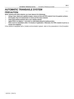
DESCRIPTION AND OPERATION
FIVE-SPEED MANUAL TRANSAXLE
This five-speed transaxle assembly adopts the synchro-
nized mesh type of 5 forward speed. The reverse speed
gear is driven by sliding idle gear without synchronizer.
REVERSE GEAR MISSHIFT
PREVENTING MECHANISM
It prevents the gear from directly being shifted from 5th
to reverse when shifting to reverse from 5th. Shift to the
reverse in neutral position to prevent the shift cam from
being interfered to the shift guide bolt.
D103B001
In case of shifting to 5th gear, shift and select shaft ro-
tates to right that shift cam aparts from guide bolt and
moves upwards by returning spring. Therefore, shifting
to reverse in this condition is impossible because of in-
terference of guide bolt.
D103B002
When shifting to reverse from neutral position between
5th and reverse, shift cam rotates to left and shifting is
possible.
D103B003
DIFFERENTIAL
Differential is integrated with transmission case and
installed on chassis together with engine. It changes the
direction of power and increase torque by reducing
speed.
Reduction gear is installed parallel to counter shaft and
is helical gear type. Differential gear is bevel gear type
and is integrated with reduction gear.
FIVE-SPEED MANUAL TRANSAXLE 5B–3
DAEWOO M-150 BL2
COMPONENT LOCATORS
GEAR SHIFT CONTROL
D13B4011
1 Gear Shift Control Lever Knob
2 Gear Shift Cable Bracket
3 Select Cable
4 Shift Cable
5 Select Arm
6 Gear Shift Control Lever
7 Gear Shift Control Lever Guide
5B–4 FIVE-SPEED MANUAL TRANSAXLE
DAEWOO M-150 BL2
INPUT SHAFT AND COUNTER SHAFT GEAR
D13B4031
FIVE-SPEED MANUAL TRANSAXLE 5B–5
DAEWOO M-150 BL2
1 Input Shaft Circlip
2 5th Gear Synchronizer Plate
3 5th Gear Synchronizer Sleeve
4 5th Gear Synchronizer Spring
5 5th Gear Synchronizer Key
6 5th Gear Synchronizer Hub
7 5th Gear Synchronizer Ring
7-1 Wave Spring
8 Input Shaft 5th Gear
9 Input Shaft 5th Gear Bearing
10 Input Shaft 5th Gear Spacer
11 Input Shaft Bearing(Left)
12 Input Shaft 4th Gear
13 4th Gear Synchronizer Ring
13-1 Wave Spring
14 Input Shaft 4th Gear Bearing
15 3rd-4th Gear Synchronizer Sleeve
16 3rd-4th Gear Synchronizer Spring
17 3rd-4th Gear Synchronizer Key
18 3rd-4th Gear Synchronizer Hub
19 3rd Gear Synchronizer Ring
20 Input Shaft 3rd Gear
21 Input Shaft 3rd Gear Bearing
22 Input Shaft
23 Input Shaft Bearing(Right)
24 Input Shaft Oil Seal
25 Reverse Gear Shaft Bolt
26 Reverse Gear Shaft
27 Reverse Idle Gear
28 Counter Shaft Nut
29 Counter Shaft 5th Gear
30 Counter Shaft Bearing Shim
31 Counter Shaft Bearing(Left)
32 Counter Shaft 4th Gear
33 Counter Shaft 3rd-4th Gear Spacer
34 Counter Shaft 3rd Gear
35 Counter Shaft 2nd Gear
36 2nd Gear Synchronizer Ring
37 Counter Shaft 2nd Gear Bearing
38 1st-2nd Gear Synchronizer Circlip
39 1st-2nd Gear Synchronizer Sleeve
40 1st-2nd Gear Synchronizer Spring
41 1st-2nd Gear Synchronizer Key
42 1st-2nd Gear Synchronizer Hub
43 1st Gear Synchronizer Ring
44 Counter Shaft 1st Gear
45 Counter Shaft 1st Gear Bearing
46 Counter Shaft
47 Counter Shaft Bearing(Right)
5B–6 FIVE-SPEED MANUAL TRANSAXLE
DAEWOO M-150 BL2
GEAR SHIFT FORK
D13B4021
1 Shift and Select Shaft
2 Shift Interlock Bolt
3 Shift Lever
4 Select Lever
5 Shift and Select Shaft Boot
6 Gearshift Control Case
7 Shift Guide Bolt
8 Gearshift Control Case Guide Plate
9 Gearshift Control Case Gasket
10 Low Speed Shift Fork
11 Low Speed Shift Shaft
12 Low Speed Shift Shaft Spring/Ball
13 Low Speed Shift York
14 High Speed Shift York
15 High Speed Shaft Spring/Ball
16 High Speed Shift Shaft
17 High Speed Shift Fork
18 Reverse Shift Arm
19 5th/Reverse Shift Ball
20 5th/Reverse Shift Shaft Spring/Ball
21 Reverse Shift Shaft Guide Spring/Ball
22 5th/Reverse Shift Shaft
23 5th/Reverse Shift York
24 5th/Shift Fork Guide Ball
25 5th/Shift Fork
26 Reverse Shift Lever
FIVE-SPEED MANUAL TRANSAXLE 5B–7
DAEWOO M-150 BL2
DIFFERENTIAL AND CASE
D13B4041
1 Speedometer Driven Gear
2 Oil Level Plug
3 Case Cap O–ring(Left)
4 Case Cap(Left)
5 Back Up Light Switch
6 Transaxle Case(Right)
7 Oil Plate
8 Transaxle Case(Left)
9 Oil Drain Plug
10 Oil Gutter
11 Side Cover Plate
12 Side Cover
13 Differential Ring Gear
14 Differential Oil Seal(Left)
15 Differential Bearing(Left)
16 Differential Case
17 Speedometer Drive Gear
18 Differential Bearing(Right)
19 Differential Oil Seal(Right)
20 Differential Pinion Gear Shaft Pin
21 Differential Side Gear Adjust Shim
22 Differential Side Gear
23 Differential Pinion Gear Shaft
24 Differential Pinion Gear
25 Differential Pinion Gear Washer
5B–8 FIVE-SPEED MANUAL TRANSAXLE
DAEWOO M-150 BL2
DIAGNOSTIC INFORMATION AND PROCEDURE
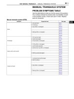
GENERAL DIAGNOSIS
Condition Probable Cause Correction
Gear Slipping Out of Mesh D Worn shift fork. D Replace shift fork.
D Worn synchronizer sleeve or gear. D Replace sleeve or gear.
D Worn bearings on input shaft or
counter shaft.
D Replace bearing.
D Weakened or damaged location
spring.
D Replace spring.
D Loose or damaged synchronizer
spring.
D Replace synchronizer spring.
D Excessive back-lash of gear. D Adjust back-lash of gear.
Gear Catching D Bent or distorted shift shaft or shift
fork.
D Replace shift shaft or shift fork.
D Weakened or damaged
synchronizer spring.
D Replace spring.
Hard Shifting D Worn synchronizer ring. D Replace synchronizer ring.
D Worn synchronizer sleeve or gear. D Replace sleeve or gear.
D Bent or distorted shift shaft. D Replace shift shaft.
D Excessive free travel of all gears
in axial direction.
D Replace gear.
D Worn bearings on input shaft or
counter shaft.
D Replace bearing.
D Poor adjustment of clutch cable. D Adjust clutch cable.
D Distorted or broken clutch disc. D Replace clutch disc.
D Damaged pressure plate. D Replace pressure plate.
Noise in the Neutral Gear D Insufficient lubricant. D Supply lubricant.
D Worn input shaft gear. D Replace gear.
D Worn bearings on the input shaft
gears.
D Replace bearing.
D Worn clutch release bearing. D Replace clutch release bearing.
Noise in the All Gears D Insufficient lubricant. D Supply lubricant.
D Worn bearings on input shaft or
counter shaft.
D Replace bearing.
D Worn input shaft or counter shaft
gear.
D Replace gear.
D Worn or damaged synchronizer
ring.
D Replace synchronizer ring.
D Worn or damaged synchronizer
sleeve.
D Replace synchronizer sleeve.
D Worn differential gear or bearing. D Replace gear or bearing.
Noise in the Peculiar Gear D Worn or damaged synchronizer
ring in the peculiar gear.
D Replace synchronizer ring.
D Worn or damaged gear in the
peculiar gear.
D Replace gear.
D Worn or damaged bearing in the
peculiar gear.
D Replace bearing.
Leak of Lubricant D Damaged gasket, oil seal or
O-ring.
D Replace gasket, oil seal or O-ing.
FIVE-SPEED MANUAL TRANSAXLE 5B–9
DAEWOO M-150 BL2
CHECKING FLUID LEVEL
Check for a leak in the area of transaxle case and seal-
ing and then check fluid level and condition after remov-
ing oil level plug.
1. Operate the engine until it comes to normal operating
temperature(Coolant temperature : 80~90°C (176~
194°F)).
2. Stall the engine and raise the vehicle.
3. Remove the oil level plug and check the fluid level.
4. The fluid should slightly flow out from the oil level plug
hole.
5. If the level is low, add the recommended fluid through
the oil level plug hole until the fluid begins to run out.
6. If the fluid is contaminated or discolored, replace it
with the recommended fluid.
7. Reinstall the oil level plug and tighten it securely.
D103B301
CHANGING FLUID
1. Operate the engine until it comes to normal operating
temperature(Coolant temperature : 80~90°C (176~
194°F)).
2. Stall the engine and raise the vehicle.
3. Drain the fluid after removing the drain plug.
4. Reinstall the drain plug and tighten it securely after
coating sealant.
5. Remove the oil level plug and replenish the fluid until
it begins to run out.
a. Oil drain plug.
b. Oil level plug.
6. Reinstall the oil level plug and tighten it securely.
Fluid Specification 75W-85(GL-4)
Fluid Capacity 2.1L(2.21qt)
Service interval Refer to Owner’s Manual
CHECKING TRANSAXLE NOISE
Many noises that appear to come from the transaxle
may actually originate with other sources such as tires,
road surfaces, wheel bearings, or engine and exhaust
system.
Identify the cause of any noise before attempting to re-
pair the clutch, the transaxle, or their related linkages.
To verify suspected transaxle noises,
1. Select a smooth, level asphalt road to reduce tyre
and resonant body noise.
2. Drive the vehicle far enough to warm up all the lubri-
cants thoroughly.
3. Record the speed and the gear range of the transaxle
when the noise occurs.
4. Check for noises with the vehicle stopped, but with
the engine running.
5. Determine if the noise occurs while the vehicle oper-
ates in.
D Drive – Under a light acceleration or a heavy pull.
D Float – Maintaining a constant speed with a light
throttle on a level road.
D Coast – With the transaxle in gear and the throttle
partly or fully closed.
D All of the above.
CHECKING BEARING NOISE
Differential Side Bearing Noise
Differential side bearing noise and wheel bearing noise
can be confused easily. Since side bearings are pre-
loaded, a differential side bearing noise should not di-
minish much when the differential/transaxle is run with
the wheels off the ground.
Wheel Bearing Noise
Wheel bearings produce a rough growl or grating sound
that will continue when the vehicle is coasting and the
transaxle is in NEUTRAL. Since wheel bearings are not
pre-loaded, a wheel bearing noise should diminish con-
siderably when the wheels are off the ground.
5B–10 FIVE-SPEED MANUAL TRANSAXLE
DAEWOO M-150 BL2
REPAIR INSTRUCTION
ON–VEHICLE SERVICE
D103B501
MANUAL TRANSAXLE ASSEMBLY
Tools Required
DW110–021 Engine Support Fixture
DW220–031 Transaxle Remove/Install Support
Removal Procedure
1. Remove the air cleaner assembly. Refer to Section
1B, SOHC Engine Mechanical.
2. Remove the battery and battery tray. Refer to Section
1E, Engine Electrical.
3. Disconnect the select and the shift cable.
D Remove the cable pins (1).
D Remove the washers (2).
D Disconnect the select and the shift cable (3).
D Remove the cable E–rings (4).
D Disconnect the cables from the cable bracket.
D103B502
4. Remove the engine wiring harness bending strap.
5. Disconnect the ground wire and the backup lamp
switch connector.
D Remove the ground wire bolt (1).
D Disconnect the ground wire (2).
D Disconnect the backup lamp switch connector (3).
FIVE-SPEED MANUAL TRANSAXLE 5B–11
DAEWOO M-150 BL2
D13B5031
6. Disconnect the radiator lower hose.
D Remove the bolts (1).
D Disconnect the radiator lower hose (2).
7. Remove crankshaft position (CKP) sensor.
D Remove the bolt (3).
D Disconnect the CKP sensor connector
D Remove the CKP sensor.
D103B507
8. Disconnect the speedometer cable.
D Loosen the nut (1).
D Disconnect the cable (2).
9. Remove the vehicle speed sensor (VSS) if
equipped.
D Disconnect VSS connector.
D Remove the VSS.
D102E502
10. Remove the starter motor.
D Remove upper two bolts that securing starter mo-
tor to transaxle.
D13B5041
11. Fix the engine assembly.
D Remove the cowl panel weatherstrip.
D Position the engine support fixture DW110–021
on the cowl panel and the front upper panel.
D Tighten the engine fixture joint with a bolt after re-
moving exhaust manifold bolt (No.4).
5B–12 FIVE-SPEED MANUAL TRANSAXLE
DAEWOO M-150 BL2
D103B510
12. Remove the transaxle upper bolts.
a. Exhaust manifold side bolt.
b. Thermostat housing side bolt.
D103B505
13. Remove the transaxle under cover.
D Remove the bolts (1).
D Remove the transaxle under cover (2).
14. Remove the front tires and wheels.
D103B506
15. Drain the transaxle fluid.
D Remove the drain plug and drain the fluid.
16. Disconnect the clutch cable.
D Remove the cable adjust nut (1).
D Disconnect the cable from the wire clip (2).
D Disconnect the cable from the transaxle mount
hole (3).
D103B509
17. Remove the front under longitudinal frames and sta-
bilizer. Refer to Section 2C, Front Suspension.
18. Remove the drive axle (only transaxle side). Refer
to Section 3B, Manual Transaxle Drive Axle.
19. Remove the clutch housing lower plate.
D Remove the bolts (1).
D Remove the lower plate (2).
FIVE-SPEED MANUAL TRANSAXLE 5B–13
DAEWOO M-150 BL2
D12B5731
20. Remove the front exhaust pipe.
D Remove the front exhaust pipe nuts (exhaust
manifold side) (1).
D Remove the gasket and separate exhaust man-
ifold pipe (2).
D Make free the front exhaust pipe.
D13B5111
21. Support the transaxle with the transaxle remove/
install support DW220–030N.
D Position the support on the jack (a).
D Support the transaxle case and mount using a
jack and the transaxle remove/install support.
D103B512
22. Remove the transaxle lower bolt and nut.
a. Lower bolt.
b. Lower nut.
D13B5131
23. Remove the transaxle mount bolts.
5B–14 FIVE-SPEED MANUAL TRANSAXLE
DAEWOO M-150 BL2
D13B5141
24. Position the manual transaxle assembly in tilting.
D To remove the manual transaxle side cover with-
out the interference with the front under longitudi-
nal panel (Left), tilt the engine/manual transaxle by
loosening the engine support fixture DW110– 021
joint with the wrench.
D13B5151
25. Remove the manual transaxle assembly.
D Lower the transaxle assembly slowly by adjusting
jack.
a. Jack.
b. Transaxle assembly.
D Tilt the transaxle assembly by adjusting jack.
D Remove the transaxle assembly by pulling and
lowering it slowly.
D103B516
26. Support the engine to normal position using the en-
gine support fixture DW110–021.
Notice: The abnormal position of the engine may dam-
age to the related parts or interfere with them. You have
to support the engine to normal position when removing
the transaxle.
Important: If it is impossible to use the special tool, sup-
port the engine to normal position with the auto jack.
D13B5171
Installation Procedure
1. Install in the reverse order of removal.
2. Install the transaxle mounting bolts.
Tighten
Tighten the transaxle mounting bolts (body side) to
45–55 NSm (33–41 lb-ft).
FIVE-SPEED MANUAL TRANSAXLE 5B–15
DAEWOO M-150 BL2
D13B518A
3. Install the transaxle lower bolt, nut.
Tighten
Tighten the bolt and nut to 55–65 NSm (41–48 lb-ft).
a. Lower bolt.
b. Lower nut.
D13B5472
4. Tighten the front exhaust pipe nuts.
Tighten
D Tighten the front exhaust pipe nuts (exhaust man-
ifold side) to 25–35 NSm (18–25 lb-ft).
D13B519A
5. Install the transaxle upper bolts.
Tighten
Tighten the bolts to 55–65 NSm (41–48 lb-ft).
a. Exhaust manifold side bolt.
b. Thermostat housing side bolt.
D13B548A
6. Install the starter motor.
Tighten
Tighten the starter motor bolts to 18–28 NSm (13–21
lb-ft).
7. Connect all electric connectors.
5B–16 FIVE-SPEED MANUAL TRANSAXLE
DAEWOO M-150 BL2
D13B5032
8. Install the radiator lower hose and crank position
(CKP) sensor.
Tighten
Tighten the radiator lower hose bolt to 8–15 NSm
(70–132 lb-in).
Tighten the CKP sensor bolt to 5–8 NSm (44–70 lb-
in).
D13B520A
9. Refill the transaxle fluid.
D Tighten the drain plug to 25–30 NSm (18–22 lb-ft)
(a).
D Remove the oil level plug (1).
D Refill recommended fluid to the proper level.
Classification 75W – 85 (GL–4)
Capacity 2.1L (2.21 qt)
D Tighten the oil level plug to 36–54 NSm (26–40 lb-ft)
(b).
D13B521A
10. Adjust the clutch cable. Refer to Section 5C, Clutch.
D Adjust the clutch cable by the clutch cable adjust
nut.
11. Install the transaxle under cover.
Tighten
Tighten the transaxle under cover bolts to 35–55
NSm (25–41 lb-ft).
D103B501
GEAR SHIFT CONTROL CASE
ASSEMBLY
Removal Procedure
1. Remove the air hose (air cleaner to throttle body).
Refer to Section 1B, SOHC Engine Mechanical.
2. Remove the battery.
3. Disconnect the select and the shift control cable.
D Remove the cable pins (1).
D Remove the washers (2).
D Disconnect the select and the shift control cable
(3).
D Remove the cable E–rings (4).
D Disconnect the cables from the cable bracket.
FIVE-SPEED MANUAL TRANSAXLE 5B–17
DAEWOO M-150 BL2
D103B522
4. Remove the select lever.
D Remove the bolts (1).
D Remove the select lever (2).
D103B523
5. Remove the shift interlock bolt.
Important: Certainly remove the shift interlock bolt.
Otherwise, the gear shift control case can not be re-
moved.
D103B524
6. Remove the gear shift control case assembly.
D Remove the bolts (1).
Important: Make sure the gear shift lever is in NEU-
TRAL.
D Remove the gear shift control case assembly (2).
D Remove the gasket (3).
D103B525
7. Remove the shift lever.
D Position the gear shift control case assembly to the
vice with a protector.
D Remove the lever pin with a pin punch and a ham-
mer (1).
D Remove the shift lever (2).
D Remove the boot (3).
5B–18 FIVE-SPEED MANUAL TRANSAXLE
DAEWOO M-150 BL2
D103B526
8. Remove the select/shift shaft.
D Remove the shift guide bolt (1).
D Remove the select/shift shaft (2).
D103B527
9. Remove the gear shift control case plate.
D Remove the bolts (1).
D Remove the Plate from the case (2).
D103B528
Inspection Procedure
1. Inspect for worn or damaged the fifth/reverse shift
cam (1).
2. Inspect for worn or damaged shift interlock plate (2).
3. Inspect for worn or damaged select/shift lever (3).
4. Inspect for bent or damaged select/shift shaft (4).
D13B529A
Installation Procedure
1. Install in the reverse order of removal.
2. Install the shift guide bolt.
Tighten
Tighten the shift guide bolt to 18–28 NSm (13–21 lb-ft).
FIVE-SPEED MANUAL TRANSAXLE 5B–19
DAEWOO M-150 BL2
D13B530A
3. Install the gear shift control case and the select lever.
Tighten
D Tighten the gear shift control case bolts to 18–28
NSm (13–21 lb-ft).
a. Gear shift control case bolt.
D Tighten the select lever bolts to 18–28 NSm (13–21
lb-ft).
b. Select lever bolt.
Important: Make sure a correct bolt. There is length dif-
ference between select lever bolts.
D13B531A
4. Install the shift interlock bolt.
Tighten
Tighten the shift interlock bolt to 18–28 NSm (13–21
lb-ft).
D103B532
SPEEDOMETER DRIVEN GEAR AND
CABLE
(Left–Hand Drive Shown, Right–Hand
Drive Similar)
Removal Procedure
1. Remove the speedometer driven gear assembly.
D Loosen the nut. (1).
D Disconnect the cable (2).
D Remove the bolt (3).
D Remove the speedometer driven gear assembly
(4).
D103B533
D Disconnect the vehicle speed sensor connector (If
equipped).
a. Vehicle speed sensor connector.
D Disconnect the vehicle speed sensor.
b. Vehicle speed sensor.
Caution: Be careful to prevent personal injury while
the exhaust pipe is hot.
5B–20 FIVE-SPEED MANUAL TRANSAXLE
DAEWOO M-150 BL2
D103B534
2. Remove the battery. Refer to Section 1E, Engine
Electrical.
3. Disconnect the instrument cluster side cable. Refer to
Section 9E, Instrumentation/Driver Information.
4. Remove the speedometer cable.
D Remove the cable grommet (1).
D Pull out the speedometer cable from the dash pan-
el.
D103B535
Inspection Procedure
1. Remove the O–ring from the speedometer driven
gear housing.
2. Remove the driven gear pin and disconnect the driv-
en gear.
D Check for a damaged or torn O–ring.
D Check for a worn or damaged tooth of driven gear.
a. O–ring.
b. Driven gear pin.
c. Driven gear.
D103B536
Installation Procedure
1. Install in the reverse order of removal.
Important: Install the speedometer driven gear assem-
bly after connecting the speedometer cable with the
speedometer driven gear assembly completely.
D13B537A
2. Install the speedometer driven gear assembly to
transaxle housing.
Tighten
Tighten the speedometer driven gear assembly bolt
to 4–7 NSm (35–62 lb-in).
FIVE-SPEED MANUAL TRANSAXLE 5B–21
DAEWOO M-150 BL2
D103B501
GEAR SHIFT CONTROL CABLE
Removal Procedure
1. Remove the air hose (air cleaner to throttle body).
Refer to Section 1B, SOHC Engine Mechanical.
2. Remove the battery.
3. Disconnect the transaxle side select and shift control
cable.
D Remove the cable pins (1).
D Remove the washers (2).
D Disconnect the select and shift control cable (3).
D Remove the cable E–rings (4).
D Disconnect the cables from the cable bracket.
D19E573A
4. Remove the floor console. Refer to Section 9G, Inte-
rior Trim.
D Put aside the floor carpet in order to get the gear
shift cable shown.
D13B5381
5. Disconnect the gear shift lever side select and shift
control cable.
D Remove the select control cable clip (1).
D Ply off the eye ring (2).
D Remove the select control cable E–ring (3).
D Disconnect the select control cable (4).
D Remove the shift control cable pin (5).
D Remove the shift control cable E–ring (6).
D Ply off the shift control cable (7).
D13B539A
6. Remove the select and shift control cable.
D Remove the nuts (1).
D Pull the cables out in the passenger room.
5B–22 FIVE-SPEED MANUAL TRANSAXLE
DAEWOO M-150 BL2
D103B540
Installation Procedure
1. Install in the reverse order of removal.
2. Push the cables toward the engine compartment
through dash panel’s hole slightly.
3. Position the cables on the select and the shift lever.
D13B5411
4. Connect the transaxle side select and shift control
cable.
5. Connect the gear shift lever side shift control cable.
6. Connect the gear shift lever side select control cable.
D Insert the select control cable eye ring to the select
arm pin (1).
D Install the selector lever control cable clip (2).
D Install the select control cable to gear shift lever
bracket with E–ring (3).
D Insert a driver to the select arm adjustment hole to
prevent the movement of gear shift lever in NEU-
TRAL (4).
7. Tighten the adjust nuts.
Tighten
Tighten the select cable adjust nut to 8–12 NSm
(71–106 lb-in).
D103B543
GEAR SHIFT CONTROL LEVER
Removal Procedure
1. Remove the floor console. Refer to Section 9G, Inte-
rior Trim.
2. Disconnect the select and shift control cable. Refer to
“Gear Shift control cable” in this section.
3. Remove the gear shift control lever assembly.
D Remove the bolts (1).
D Remove the gear shift control lever assembly (2).
D Remove the gear shift lever sensor connector.
(If equipped with auto clutch).
FIVE-SPEED MANUAL TRANSAXLE 5B–23
DAEWOO M-150 BL2
D13B544A
Installation Procedure
1. Install in the reverse order of removal.
2. Install the gear shift control lever assembly.
Tighten
Tighten the bolts to 4–7 NSm (35–62 lb-in).
3. Adjust the select cables. Refer to “Gear Shift Control
Cable” in this section.
5B–24 FIVE-SPEED MANUAL TRANSAXLE
DAEWOO M-150 BL2
MAINTENANCE AND REPAIR
UNIT REPAIR
D13B701A
GEAR UNIT
Tools Required
09913–76010 Bushing, Seal Installer
DW09940–53111 Gear, Bearing Installer
DW09943–78210 Bushing, Seal Installer
DW220–010A Transaxle Fixture
KM519 Oil Seal Installer
Disassembly Procedure
1. Remove the manual transaxle. Refer to “Manual
Transaxle Assembly” in this section.
2. Position the manual transaxle to a transaxle stand us-
ing the transaxle fixture DW220–010.
D13B7021
3. Remove the related clutch parts. Refer to Section 5C,
Clutch.
4. Remove the manual transaxle mounting bracket.
D Remove the bolts (1).
D Remove the nut (2).
D Remove the mounting bracket (3).
D103B703
5. Disconnect the backup light switch and speedometer
driven gear assembly.
D Remove the nut (1).
D Disconnect the backup light switch (2).
D Remove the bolt (3).
D Remove the speedometer driven gear assembly
(4).
FIVE-SPEED MANUAL TRANSAXLE 5B–25
DAEWOO M-150 BL2
D103B704
6. Remove the select lever.
D Remove the bolt (1).
D Remove the select lever (2).
D103B705
7. Remove the gear shift control case assembly.
D Remove the bolts (1).
D Remove the shift interlock bolt (2).
Important: Certainly remove the shift interlock bolt.
Otherwise, gear shift control case can not be removed.
D Remove the gear shift control case assembly (3).
D Remove the gasket (4).
D103B706
8. Remove the side cover.
D Remove the bolts (1).
D Remove the side cover using a rubber hammer (2).
D Remove the sealant on the side cover and the
transaxle case.
D103B707
9. Remove the fifth–gear shift fork guide ball, the snap
ring and the input shaft fifth–gear snap ring.
D Remove the fifth–gear shift fork plug (1).
D Remove the guide ball using a magnet.
D Remove the fifth–gear shift fork snap ring (2).
D Remove the fifth–gear snap ring (3).
D Remove the fifth–gear synchronizer plate.