- Trang chủ >>
- Khoa Học Tự Nhiên >>
- Vật lý
nanotechnology in medical applications state of the art in materials
Bạn đang xem bản rút gọn của tài liệu. Xem và tải ngay bản đầy đủ của tài liệu tại đây (667.71 KB, 167 trang )
VRAE
MULTI GAS MONITOR
PGM-7800 & 7840
OPERATION AND MAINTENANCE
MANUAL
(Document No.: 017-4001)
Rev. E
RAE SYSTEMS INC.
1339 Moffett Park Drive
Sunnyvale, CA 94089
July 2001
RAE Systems Product Line
Gas Detection Tubes & Pumps
SampleRAE Electronic Tube Pump
MultiRAE PLUS Multi-gas Monitors
MultiRAE Confined Space Monitor
QRAE PLUS Multi-gas Monitors
QRAE Confined Space Monitor
VRAE Five Gas Surveyor
MiniRAE 2000 Portable VOC Monitor (PID)
UltraRAE Specific Compound Monitor
CDRAE Corona Discharge VOC Monitor
ToxiRAE PLUS PID Monitor
ToxiRAE PLUS Single Gas Monitors
ToxiRAE PLUS Oxygen Monitor
ToxiRAE PLUS Combustible Gas Monitor
MiniRAE PLUS Classic PID
ModuRAE Fixed System PID
AreaRAE Wireless Multi-point, Multi-gas Detection
Systems
How can I be informed and updated?
Be sure to mail in your warranty card, email or fax us to get on
RAE’s private database (information is never supplied to others).
You will be updated on new products, technical advisory notices,
new accessories and much more. Thank you for your purchase!
i
Table of Contents
1. GENERAL INFORMATION 1-1
1.1 General Specifications 1-2
2 OPERATION OF VRAE 2-1
2.1 Physical Description 2-2
2.2 Keys and Display 2-4
2.3 Power On/Off 2-7
2.4 Operations 2-10
2.5 Alarm Signals 2-18
2.6 Back Light 2-21
2.7 Preset Alarm Limits and Calibration 2-22
2.8 Integrated Sampling Pump 2-23
2.9 Datalogging 2-24
3 OPERATION OF ACCESSORIES 3-1
3.1 Battery Charging Operation 3-2
3.2 Alkaline Battery Adapter 3-5
3.3 Water Trap Filter 3-6
4 PROGRAMMING OF VRAE 4-1
4.1 Programming Mode 4-2
4.2 Keys for Programming Mode 4-4
4.3 Entering into Programming Menu 4-5
4.4 Calibration of VRAE Monitor 4-7
4.4.1 Fresh Air Calibration 4-8
4.4.2 Multiple Sensor Calibration 4-10
4.4.3 Single Sensor Calibration 4-13
4.4.4 Modify Span Gas Value 4-16
4.4.5 Change LEL Span Gas 4-17
4.5 Change Alarm Limits 4-19
4.6 View or Change Datalog 4-21
4.6.1 Reset Peak and Minimum 4-22
4.6.2 Clear All Data 4-23
4.6.3 Change Datalog Period 4-24
4.6.4 Select Data Type 4-25
4.6.5 View Datalog 4-26
4.6.6 Enable/Disable Datalog 4-27
4.7 Change Monitor Setup 4-28
4.7.1 Change Site ID & Change User ID 4-29
4.7.2 Change Alarm Mode 4-30
4.7.3 Change User Mode 4-31
4.7.4 Change Real Time Clock 4-32
ii
4.7.5 Change Back Light Mode 4-33
4.7.6 Change Password 4-34
4.7.7 Change Pump Speed 4-35
4.7.8 Change Averaging Method 4-36
4.7.9 Change Temperature Unit 4-37
4.8 Change Sensor Configuration 4-38
4.8.1 Change LEL/VOL Sensor Type 4-40
4.8.2 Enable/Disable Sensor 4-41
4.8.3 Change Dilution Ratio 4-42
4.8.4 Change LEL/VOL Gas Selection 4-43
4.9 Exit Programming Mode 4-45
5 COMPUTER INTERFACE 5-1
5.1 Install ProRAE-Suite Software 5-2
5.2 Connect VRAE to PC 5-4
5.3 Start ProRAE-Suite Software 5-5
5.4 Setup Communication Port 5-7
5.5 Process the Configuration Data 5-8
5.5.1 Edit the Configuration Data 5-9
5.5.2 Send Configuration to VRAE 5-21
5.5.3 Receive Configuration Data 5-22
5.5.4 Configure All Settings 5-23
5.6 Process the Logged Data 5-24
5.6.1 Receive Data from VRAE 5-25
5.6.2 View Logged Data in Text Mode 5-26
5.6.3 View STEL/TWA/AVG Value 5-28
5.6.4 View Summary Information 5-29
5.6.5 View Logged Data in Graph Mode 5-30
5.6.6 Export the Displayed Data to a Text File 5-33
5.6.7 Export a Graph to a File 5-34
5.6.8 Print the Logged Data 5-35
5.7 Upgrade the Datalog Option 5-36
5.8 Upgrade the Firmware 5-38
6 THEORY OF OPERATION 6-1
7 MAINTENANCE 7-1
7.1 Battery Replacement 7-2
7.2 Sensor Replacement 7-4
7.3 Sampling Pump Replacement 7-6
8 TROUBLESHOOTING 8-1
8.1 Special Diagnostic Mode 8-2
8.2 Troubleshooting Table 8-9
APPENDIX A. QUICK REFERENCE GUIDE A-1
iii
APPENDIX B. RESPONSE INFORMATION B-1
APPENDIX C. V-RAE DATA CONVERSION TO
MICROSOFT EXCEL
C-1
APPENDIX D. RAE SYSTEMS TECHNICAL NOTES D-1
APPENDIX E. RAE SYSTEMS APPLICATION NOTES…… E-1
APPENDIX F. LITERATURE REQUEST FORM…………… … F-1
APPENDIX G. RETURN AUTHORIZATION FORM…………… G-1
Main Contact Numbers…………………………………Outer Back Cover
iv
! WARNING !
- DO NOT proceed before reading -
This manual must be carefully read by all individuals
who have or will have the responsibility for using,
maintaining, or servicing this product.
The product will perform as designed only if it is used,
maintained, and serviced in accordance with the
manufacturer's instructions.
CAUTION!!
To reduce the risk of electric shock, turn off power
before removing the monitor cover. Disconnect the
battery before removing sensor module for service.
Never operate the monitor while the cover is removed.
Remove monitor cover and sensor module only in an
area known to be non-hazardous.
The model PGM-7800 and PGM-7840 equipment are
classified as to intrinsic safety for use in class I, division
1, groups A, B, C, D, or non-hazardous locations only.
v
Special Notes
-1-
When the PGM-7800 or PGM-7840 Multi gas monitor is
taken out from the transport case and turned on for the
first time, there may be some residual organic or
inorganic vapor trapped inside the detector chamber.
The initial toxic sensor reading may indicate a few ppm.
Ensure an area free of toxic vapor and turn on the
monitor. After running for several minutes, the residual
vapor in the detector chamber will be cleared and the
reading should return to zero.
-2-
The battery of the VRAE monitor will discharge slowly
even if it is turned off. If the monitor has not been
charged for 5-7 days, the battery voltage will be low.
Therefore, it is a good practice to always charge the
monitor before using it. It is also recommended to fully
charge the monitor for AT LEAST 10 HOURS before
initial use. See Section 7 for more information on
battery charging and replacement.
-3-
When a monitor is turned on the first time, or after a
long time without use, the real time clock of the unit
may not work properly, error messages may indicate
sensor expired. That is due to the incorrect time on the
clock. After fully-charging the monitor, enter the
correct time and date again to ensure that no more
erroneous messages are displayed.
vi
WARNINGS:
Use only RAE Systems battery packs, part Nos. 012-
3050, 012-3051 or 012-3052. This instrument has not
been tested in an explosive gas/air atmosphere
having an oxygen concentration greater than 21%.
Substitution of components may impair intrinsic
safety. Recharge batteries only in non-hazardous
locations.
AVERTISSEMENT:
Utiliser seulement l'ensemble de batterie RAE
Systems, la reference 012-3050, 012-3051 au 012-
3052. Cet instrument n’a pas été essayé dans une
atmosphère de gaz/air explosive ayant une
concentration d’oxygène plus élevée que 21%. La
substitution de composants puet compromettre la
sécurité intrinsique. Ne charger les batteries que
dans emplacements désignés non dangereux.
STATIC HAZARD:
Clean only with a damp cloth.
DANGER RISQUE D'ORIGINE
ELECTROSTATIQUE:
Nettoyer uniquement avec un chiffon humide.
vii
CAUTION:
For safety reasons this equipment must be operated
and serviced by qualified personnel only. Read and
understand instruction manual completely before
operating or servicing.
ATTENTION:
Pour des raisons de sécurité, cet équipment doit être
utilisé, entretenu et réparé uniquement par un
personnel qualifié. Étudier le manuel d’instructions
en entier avant d’utiliser, d’entretenir ou de réparer
l’équipement.
CALIBRATION WARNINGS:
The calibration of all newly purchased RAE Systems
instruments should be tested by exposing the
sensor(s) to known concentration calibration gas(es)
before putting the unit into service for the first time.
For maximum safety, the accuracy of the VRAE
should be checked by exposing the sensor(s) to
known concentration calibration gas(es) before each
day’s use.
viii
AVERTISSEMENT:
La calibration de toute instruments de RAE Systems
doivent être testé en exposant l’instrument a une
concentration de gaz connue par une procédure
dietalonnage avant de mettre en service l’instrument
pour la première fois.
Pour une securite maximale, la sensibilité du VRAE
doit être verifier en exposant l’instrument a une
concentration de gaz connue par une procédure
dietalonnage avant chaque utilisation journalière.
CAUTION:
Any rapid up-scale reading followed by a declining
or erratic reading may indicate a gas concentration
above the upper scale limit, which may be hazardous.
AVERTISSEMENT:
Toute lecture rapide et positive, suivie d’une baisse
subite au erratique de la valeur, peut indiquer une
concentration de gaz hors gamme de détection qui
peut être dangereuse.
GENERAL INFORMATION
1 - 1
1 GENERAL INFORMATION
The VRAE is a programmable multi gas monitor designed
to provide continuous exposure monitoring of toxic gases,
oxygen and combustible gases for workers in hazardous
environments. Two models of VRAE are available: PGM-
7800 and PGM-7840. The PGM-7840 has one more
inorganic toxic sensor in lieu of an oxygen sensor in the
PGM-7800. The figures and displays shown in this
manual are primarily for the model PGM-7800. For
the model PGM-7840, the displays will be similar.
However, the oxygen reading will be replaced by a toxic
sensor reading, and the name “oxy” will be replaced by
the name of the toxic sensor.
The VRAE monitor detects inorganic toxic gases and
oxygen concentration with the electrochemical sensors. It
also monitors combustible gases with a catalytic bead
sensor and a broad range of gases with a thermal
conductivity detector. Other features include:
• Lightweight and Compact
- 19 oz (540 g), walkie–talkie size.
• Dependable and Accurate
- 10 hours monitoring with micro-controller.
• User Friendly
- Menu driven, intuitive end-use operation.
• Programmable Alarm Thresholds
- Audio buzzer & flashing display alarm.
GENERAL INFORMATION
1 - 2
1.1 General Specifications
Table 1.1
VRAE Gas Monitor Specification
Dimensions: 7.75”L x 2.75”W x 1.5”H
(19.6 cm x 7.0 cm x 3.8 cm)
Weight: 19 oz (540 g) with battery.
Detector: 5 sensors: electrochemical sensors for
toxic gases, oxygen sensor, catalytic bead
for combustible gases and thermal
conductivity detector (TCD) for a broad
range of gases.
PGM-7800: oxygen, combustible, TCD
and three toxic gas sensors.
PGM-7840: one combustible/TCD and
four toxic gas sensors.
Battery: Rechargeable, 4.8V/1250 mAh, Ni-MH
battery pack with built-in charger (10
hours charge time) or a 4 AA alkaline
battery adapter.
Operating Time: Up to 10 hours continuous operation.
Display: 2-line, 16 digit LCD with LED back light
automatically in dim light.
Keypad: 1 operation key and 2 programming keys.
Direct Readout: Instantaneous values (up to 5), sensor
name, high and low values for all
detectors, TWA and STEL values for
toxic, battery voltage and elapsed time.
GENERAL INFORMATION
1 - 3
Multi Gas Monitor Specification
(Continued)
Alarm Settings: Separate alarm limit settings for TWA,
STEL, Low and High alarm.
Range, Resolution and Response Time (t
90
diffusion):
CO 0-500 ppm 1 ppm 40 sec
H
2
S 0-100 ppm 1 ppm 35 sec
SO
2
0-20 ppm 0.1 ppm 35 sec
NO 0-250 ppm 1 ppm 30 sec
NO
2
0-20 ppm 0.1 ppm 25 sec
Cl
2
0-10 ppm 0.1 ppm 60 sec
O
2
0-30 % 0.1 % 15 sec
LEL 0-100 % 1 % 15 sec
VOL 0–100% 1% 20 sec
HCN 0-100 ppm 1 ppm 200 sec
NH
3
0-50 ppm 1 ppm 150 sec
PH
3
0-5 ppm 0.1 ppm 60 sec
ClO
2
0-1 ppm 0.1 ppm 150 sec
Alarm: 90 dB buzzer and flashing red LED to
indicate exceeded preset limits, low
battery, or sensor failure.
Calibration: Two-point field calibration for fresh air
and standard reference gas.
Attachment: Rubber boot, belt clip and wrist strap.
Sampling Pump: Internal integrated with 400 cc/min flow
rate (high setting).
Protection: Password protected calibration settings,
alarm limits, and data.
GENERAL INFORMATION
1 - 4
Multi Gas Monitor Specification
(Continued)
Intrinsic Safety: UL & cUL Class 1, Division I, Group A,
B, C, D (US & Canada), EEx ia IIC T2
(Europe).
EM Immunity: No effect when exposed to 0.43mW /cm
2
RF interference (5 watt transmitter at 12
inches).
Data Storage: 16,000 readings (54 hours, 5 channels at 1
minute interval) in non-volatile memory.
Datalog Interval: Programmable 1-3600 sec.
External Alarm: Optional plug in pen size vibration alarm.
External Printer: Optional plug in serial thermal printer.
Communication: Download data to PC and upload monitor
setup from PC through RS-232 link to
serial port on PC.
Temperature: -20
o
to 45
o
C (-4
o
to 113
o
F).
Humidity: 0 % to 95% relative humidity.
(non-condensing)
Configuration: 2, 3, 4 and 5 gas with/without
datalogging.
OPERATION OF VRAE
2 - 1
2 OPERATION OF VRAE
The VRAE Monitor is a walkie-talkie size multi-gas
exposure monitor. It gives real time measurements and
activates alarm signals whenever the exposure exceeds
preset limits. Prior to factory shipment, the VRAE is
preset with default alarm limits and the sensors are pre-
calibrated with standard calibration gas. However, the user
should calibrate the instrument before the first use. After
the monitor is fully charged and calibrated, it is ready for
immediate operation.
OPERATION OF VRAE
2 - 2
2.1 Physical Description
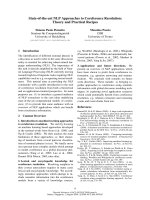
Figure 2.1 shows the main components of the VRAE Multi
gas monitor which include:
Figure 2.1 Major parts of the VRAE Multi Gas
Monitor
• 3 keys for the user to interact with the monitor: 1
operation key and 2 programming keys for normal
operation or programming of the monitor.
• LCD display with backlight to show real time and
calculated measurements.
• Buzzer and red LED for alarm signal whenever the
exposures exceed preset limits.
Charge contact
Keys
LCD Display
LED alarm
Serial port
Wrist strap
Gas Outlet
Gas Inlet
OPERATION OF VRAE
2 - 3
• Wrist strap.
• Charge contact for plugging directly to the charging
station.
• Gas entry and exit port.
• Serial communication port for PC interface.
• Analog output and external alarm output port.
OPERATION OF VRAE
2 - 4
2.2 Keys and Display
Figure 2.2 shows the LCD display and the keypad on the
front panel of the monitor. The functions of the 3 keys
during normal operation are summarized in Table 2.1 on
the next page:
Figure 2.2 Keypad and Display of the VRAE
Multi Gas Monitor
MODE
N/-
Y/+
ON
Charging LED
Light Sensor
Alarm LED
OPERATION OF VRAE
2 - 5
Table 2.1
Key Function in Normal Operation
[MODE]: Turn on/off the power* and choose
different display mode.
[N/-]: Toggle on/off the backlight.
[Y/+]: Alarm test and alarm acknowledge
(turn off latched alarm, turn on pump or
LEL sensor).
* Pressing and holding [MODE] key for 5 seconds turns off
the power to the monitor. Monitor will beep once per
second during power-down sequence. Press [MODE] key
momentarily to choose different display modes (see
Section 2.4 for details).
Display
The VRAE multi gas monitor includes a 2-line, 16-digit
dot matrix LCD display. The LCD shows the following
eight types of displays during normal operation if the
[MODE] key is pressed:
• Real time instantaneous gas concentration in ppm
for toxic gases, % by volume for oxygen (not
applicable to PGM-7840) and both % by volume
and %LEL for combustible gases.
• Sensor names.
OPERATION OF VRAE
2 - 6
• Peak and minimum gas concentrations for toxic,
oxygen (not applicable to PGM-7840) and
combustible gases.
• 8-hour Time Weighted Average (TWA) or running
average and 15 minute Short Term Exposure Limit
(STEL) values of the toxic gases in ppm.
• Battery voltage and shut down voltage in volts.
• Real time clock, run time and temperature.
• Datalogging mode or “Start/Stop Datalog?” menu to
to turn datalogging on/off if manual datalogging
mode is selected.
• LEL/VOL gas names (if the LEL or LEL/VOL
sensor is installed).
• Pump speed adjustment (High/Low)
• LEL/VOL sensor operating mode selection.
• “Communicate with PC?” menu to send or receive
data between PC and the VRAE monitor.
OPERATION OF VRAE
2 - 7
2.3 Power On/Off
To turn on the VRAE multi gas monitor, press the
[MODE] key. The audio buzzer will beep once and the
display will show “ON! ” and then “MultiGas Monitor Ver
n.nn” to indicate the software version number. Serial
number, current date and time, temperature of the monitor
are displayed next. The monitor will then go through each
sensor socket to check if a valid sensor is installed. If a
new sensor is installed, a message to remind the user to
calibrate the sensor will be displayed followed by a
message that the alarm limits have been reset to default
values for the new sensor. If a sensor reaches its expected
end of life, a “Warranty Expired” message will be
displayed. The sensor can be used beyond this date if it still
calibrates properly and has enough resolution as tested by
the raw readings (see Section 8 and Technical Note 123).
Next, the monitor displays the preset alarm limits for each
sensor, battery voltage, shut down voltage, user mode,
alarm mode, datalog mode, available data storage memory
(in hours), datalog mode and datalog interval (in seconds).
Then after a warm-up interval (default of 10 seconds), the
VRAE monitor is ready to monitor gases, and the display
shows the instantaneous reading of the gas concentration in
ppm.
To turn off the VRAE multi gas monitor, press and hold
the [MODE] key for 5 seconds. The monitor will beep
once per second during the power-down sequence with a
count down timer showing the number of remaining
OPERATION OF VRAE
2 - 8
seconds. The message “Off! ” flashes on the LCD display
and the display will go blank, indicating that the monitor is
turned off.
Turning off the multi gas monitor with the AC adapter in
place will result in a display of “Charging ” or “Battery
Charged” and indication of battery voltage. This indicates
that the monitor is off, but the smart charger circuit is now
active.
To turn the unit on from the charge or discharge mode,
press the [MODE] key.
Data protection during power off
When the monitor is turned off, all the current real time
data including TWA, STEL, Peak and elapsed time are
erased. However, the datalog data is preserved in non-
volatile memory. Even if the battery is disconnected, the
datalog data will not be lost. During the power off period,
the real time clock will continue to operate until the battery
is completely drained (usually in 5-7 days without any
charging). If the battery is completely drained or is
disconnected from the monitor for more than 30 minutes,
the real time clock will be lost. In this case, the user needs
to enter the real time clock information again, as described
in Section 4.
Datalog versus Non Datalog monitor
The VRAE multi-gas monitor is available either with or
without the Datalog option. During the power on
sequence, a letter “D” following the version number
indicates that the monitor is configured as a Datalog
OPERATION OF VRAE
2 - 9
monitor. Without the letter “D”, it is a Non-Datalog
monitor.
The user can upgrade a Non-Datalog monitor to a Datalog
monitor. Call the factory for information on how to order
the upgrade kit.
For instructions and operations of datalog features, please
refer to Sections 4.6 and 5 of this manual.
OPERATION OF VRAE
2 - 10
2.4 Operations
The VRAE multi gas monitor offers three different user
modes of operation:
Text mode,
Display mode, and
Program mode.
The text mode is the simplest mode of operation. The
monitor will display the sensor name after the monitor is
turned on. The user can press the [MODE] key to see the
instantaneous gas concentration readings, battery voltage or
enter the PC communication menu.
The display sequence in text mode.
The four displays are arranged in a “round robin” order:
To choose a specific display, press the [MODE] key one or
more times until the desired display appears.
In the display mode, the VRAE multi gas monitor
displays eight different readings: instantaneous gas
concentration, sensor name, Peak, minimum, STEL, TWA,
battery voltage and shut down voltage in volt, run time in
hours and minutes and temperature in degree F. In
addition, there are up to five more displays to show datalog
mode (or enable / disable datalogging operation in manual
Sensor Names
Comm with
PC?
Instantaneous
Battery Voltage
OPERATION OF VRAE
2 - 11
datalog mode), to show the LEL gas names, to show pump
speed, and to print reading (Option) and to communicate
with a PC.
In the program mode, the user can perform all of the
functions of the display mode. In addition, the user can
enter a Programming Mode. In the programming mode,
the user can perform various functions, such as change
sensor configurations, enter user information or calibrate
the monitor, etc. The programming mode will be explained
in detail in Section 4. Below is the display sequence in
display and program mode.
The thirteen displays are arranged in a “round robin” order:
* Appears only if the option is enabled.
Run time, Clock
Temperature
Instantaneous
Min. Value
Comm with PC?
Peak Value
LEL Gas Name STEL Value
Sensor Name
Start/Stop Dlog?*
Battery Voltage
TWA Value
Pump Speed H/L
Print Reading?*