optical properties of nanostructured metallic systems studied with the finite-difference time-domain method
Bạn đang xem bản rút gọn của tài liệu. Xem và tải ngay bản đầy đủ của tài liệu tại đây (8.8 MB, 177 trang )
Springer Theses
Recognizing Outstanding Ph.D. Research
For further volumes:
/>Aims and Scope
The series ‘‘Springer Theses’’ brings together a selection of the very best Ph.D.
theses from around the world and across the physical sciences. Nominated and
endorsed by two recognized specialists, each published volume has been selected
for its scientific excellence and the high impact of its contents for the pertinent
field of research. For greater accessibility to non-specialists, the published versions
include an extended introduction, as well as a foreword by the student’s supervisor
explaining the special relevance of the work for the field. As a whole, the series
will provide a valuable resource both for newcomers to the research fields
described, and for other scientists seeking detailed background information on
special questions. Finally, it provides an accredited documentation of the valuable
contributions made by today’s younger generation of scientists.
Theses are accepted into the series by invited nomination
only and must fulfill all of the following criteria
• They must be written in good English.
• The topic should fall within the confines of Chemistry, Physics and related
interdisciplinary fields such as Materials, Nanoscience, Chemical Engineering,
Complex Systems and Biophysics.
• The work reported in the thesis must represent a significant scientific advance.
• If the thesis includes previously published material, permission to reproduce this
must be gained from the respective copyright holder.
• They must have been examined and passed during the 12 months prior to
nomination.
• Each thesis should include a foreword by the supervisor outlining the signifi-
cance of its content.
• The theses should have a clearly defined structure including an introduction
accessible to scientists not expert in that particular field.
Sergio G. Rodrigo
Optical Properties of
Nanostructured Metallic
Systems
Studied with the Finite-Difference
Time-Domain Method
Doctoral Thesis accepted by
The University of Zaragoza, Spain
123
Author
Dr. Sergio G. Rodrigo
Departamento de Física de la Materia
Condensada
Instituto de Ciencia de Materiales de
Aragón
Universidad de Zaragoza
50009 Zaragoza
Spain
e-mail:
Supervisors
Prof. Dr. Luis Martín-Moreno
Departamento de Física de la Materia
Condensada
Instituto de Ciencia de Materiales de
Aragón
Universidad de Zaragoza
50009 Zaragoza
Spain
e-mail:
Prof. Dr. Francisco José García-Vidal
Departamento de Física Teórica de la
Materia Condensada
Universidad Autónoma de Madrid
28049 Madrid
Spain
e-mail:
ISSN 2190-5053 e-ISSN 2190-5061
ISBN 978-3-642-23084-4 e-ISBN 978-3-642-23085-1
DOI 10.1007/978-3-642-23085-1
Springer Heidelberg Dordrecht London New York
Library of Congress Control Number: 2011938012
Ó Springer-Verlag Berlin Heidelberg 2012
This work is subject to copyright. All rights are reserved, whether the whole or part of the material is
concerned, specifically the rights of translation, reprinting, reuse of illustrations, recitation, broadcast-
ing, reproduction on microfilm or in any other way, and storage in data banks. Duplication of this
publication or parts thereof is permitted only under the provisions of the German Copyright Law of
September 9, 1965, in its current version, and permission for use must always be obtained from
Springer. Violations are liable to prosecution under the German Copyright Law.
The use of general descriptive names, registered names, trademarks, etc. in this publication does not
imply, even in the absence of a specific statement, that such names are exempt from the relevant
protective laws and regulations and therefore free for general use.
Cover design: eStudio Calamar, Berlin/Figueres
Printed on acid-free paper
Springer is part of Springer Science+Business Media (www.springer.com)
A mis padres
Supervisors’ Foreword
The discovery of the laws of electromagnetism (EM) in the nineteenth century
triggered an amazing wealth of scientific developments, which have had a pro-
found impact on our society.
Electromagnetism has been developed in many different directions and regimes.
However, until recently, the study of electromagnetic fields interacting with
objects of size smaller than, but of the order of, the wavelength of the field
remained largely unexplored. The reason was the failure, in that regime, of the
highly successful approximations that had allowed the development of most of
electromagnetic phenomena, namely circuit theory (which applies when scatterers
are much smaller than the wavelength) and ray optics (valid when the objects that
the field encounters are much larger than its wavelength). Without these tools
Maxwell equations were, except in the simplest geometries (presenting a high
degree of symmetry, as plane surfaces, spheres ), simply too difficult to handle
with existing mathematics.
This represented not only a nagging gap in fundamental science. The present
control of sizes and positions of objects in the scale of tens of nanometers has
made the understanding of their interaction with light imperative from the tech-
nological point of view. Fortunately, computers have evolved very fast and, since
the 1990s, are powerful enough both speed- and memorywise to allow solution of
Maxwell’s equations for many of the basic geometries. Today, this combination of
improved manufacturing and computing capabilities is triggering a scientific
explosion in what it is now known as the field of Nanophotonics.
Still, the numerical problem is a very difficult one, due to the many different
length scales involved, which range from grid sizes of the order of 2–5 nm (needed
to describe the penetration of fields in metals) to tens of microns for a small system
comprising a few subwavelength objects resonantly coupled.
Nowadays, several computational schemes for solving Maxwell equations have
been developed but, due to the inherent complexity of the problem, it is not clear
yet which is the best one (or even if there is one that is best for most cases). This
thesis focuses on the application of one of the most promising methods, the finite-
difference time-domain method (FDTD), to Nanophotonics.
vii
In a nutshell, in FDTD an incident electromagnetic wavefield is propagated in
discretized space and discretized time, according to both Maxwell equations and
the constitutive relations (which state how materials respond to the EM field). This
information is then post-processed to obtain the EM response of the considered
system. This method was originally proposed in 1966 by K. Yee, and has been
developed over the years, existing now excellent books about (see references in the
text). The work presented here closely followed these references. Nevertheless, the
actual implementation of a home-made FDTD code still faces some technical
problems; the solution to several of them can be found in the text.
The present thesis is, however, not about the FDTD method, but about its
application to some physical problems related to the control of EM fields close to
metal surfaces. The topics considered include the several aspects on how light
transmits through subwavelength apertures in corrugated metal films (such as the
influence of the metal, dependence on the metal thickness and the study of optical
properties of metal coated microspheres), the optical properties of metamaterials
made with stacked hole arrays and the guiding of metallic waveguides (and their
focusing capabilities when tapered). These systems are thoroughly analyzed and,
whenever possible, the numerical calculations have been accompanied by sim-
plified models that help extract the relevant physical mechanisms at work.
Notably, the thesis also presents many comparisons with experimental data.
That this comparison works without the need for a large number of additional
fitting parameters is not trivial, as the quality of materials (and thus their optical
properties) may, in principle, be altered when these are patterned. The good
agreement obtained between experiments and calculations using available data for
bulk materials (i.e. without adding fitting parameters) suggests that theory can
already be used as a predictive tool in this area.
To summarize, this thesis analyses a large number of topics of current interest
in Nanophotonics and the optical properties of nanostructured metals, and presents
a short introduction to the FDTD Method. Hopefully, it will be useful both to
researchers interested in this numerical method and to those attracted to the field of
optical properties of nano- and micro- structured metals.
Zaragoza, Madrid, August 2011 Luis Martín-Moreno
Francisco José García-Vidal
viii Supervisors’ Foreword
Preface
As everybody has experienced by looking at a mirror, light is almost completely
reflected by metals. But they also exhibit an amazing property that is not so widely
known: under some circumstances light can ‘‘flow’’ on a metallic surface as if it
were ‘‘glued’’ to it. These ‘‘surface’’ waves are called surface plasmon polaritons
(SPPs) and they were discovered by Rufus Ritchie in the middle of the past
century. Roughly speaking, SPP modes generate typically from the coupling
between conduction electrons in metals and electromagnetic fields. Free electrons
loose their energy as heat, which is the reason why SPP waves are completely
absorbed (in the visible range after a few tens microns). These modes decay
through so short lengths that they were considered a drawback, until a few years
ago. Nowadays that situation has completely turned. Nano-technology now opens
the door for using SPP-based devices for their potential in subwavelength optics,
light generation, data storage, microscopy and bio-technology.
There is a lot of research done on those phenomena where SPPs are involved,
however there is still a lot of work to do in order to fully understand the properties
of these modes, and exploit them. Precisely, throughout this thesis the reader will
find a part of the efforts done by our collaborators and ourselves to understand the
compelling questions arising when light ‘‘plays’’ with metals at the nanoscale. The
outline of the thesis is:
i. Chapter 1: Introduction
First, the fundamentals of SPPs are introduced. In fact, SPPs will be one of
the most important ingredients in order to explain the physical phenomena
investigated in this thesis.
Our contributions, from a technical standpoint, have been carried out with the
help of two different well known theoretical methods: the finite-difference
time-domain (FDTD) and the coupled mode method (CMM). In this chapter,
we summarize the most relevant aspects of these two techniques, looking for
a better comprehension of the discussions raised along the remaining
chapters.
ix
Concerning the rest of experimental and theoretical techniques used, it is out
of the scope of this thesis to rigorously describe all of them. Nevertheless,
most of those methods, which will not be presented in the introductory
chapter, will be briefly explained when mentioned.
ii. Chapter 2: Extraordinary Optical Transmission
Imagine someone telling you that a soccer ball can go through an engage-
ment ring. At first, you could think that he or she has got completely mad. A
situation like that could have been lived by the researchers who first reported
on the extraordinary optical transmission (EOT) phenomenon. Thomas
Ebbesen and coworkers found something like a ‘‘big’’ ball passing through a
hole several times smaller than it, although there, the role of the ball was
played by light. Before Ebbesen’s discovery light was not been thought of
being substantially transmitted through subwavelength holes. Until 1998, a
theory elaborated by Hans Bethe, on the transmission through a single cir-
cular hole in a infinitesimally thin perfect conducting screen, had ‘‘screened’’
out any interest in investigating what occurs for holes of subwavelength
dimensions. Bethe’s theory demonstrated that transmission through a single
hole, in the system described above, is proportional to ðr=kÞ
4
where k is the
wavelength of the incoming light, and r is the radius of the hole. The pro-
portionally constant depends on hole shape, but it is a small number (*0.24
for circular holes). It is clear that whenever k ) r transmission is negligible.
Nevertheless, Ebbesen and coworkers experimentally found that light might
pass through subwavelength holes if they were periodically arranged on a
metal surface. More importantly, in some cases even the light directly
impinging into the metal surface, and not onto the holes, is transmitted. The
SPP modes were pointed to be responsible of EOT.
It is not strange that such a breakthrough sparked a lot of attention in the
scientific community. Furthermore, the EOT discovery is not only interesting
from the fundamental physics point of view, but from the technological side
as well.
The EOT phenomenon strongly depends on both geometrical parameters and
material properties. Moreover, EOT does not only occur in two dimensional
hole arrays (2DHAs), so other systems have been investigated in the last
years. In this way, this thesis is partly devoted to study different aspects of
EOT:
(a) We begin by investigating the influence of the chosen metal on EOT
using the FDTD method. We analyze transmission spectra through hole
arrays drilled in several optically thick metal films (viz. Ag, Au, Cu, Al,
Ni, Cr and W) for several periods and hole diameters proportional to the
period.
(b) We also study the optical transmission through optically thin films,
where the transmission of the electromagnetic field may occur through
both the holes and the metal layer, conversely to the ‘‘canonical’’
x Preface
configuration where the metal film is optically thick, and the coupling
between metal sides can only be through the holes.
(c) On the other hand, since the first experimental and theoretical papers
some controversy arose over the mechanisms responsible to enhance
optical transmission through an array of holes. Two mechanisms lead to
enhanced transmission of light in 2DHAs: excitation of SPPs and
localized resonances, which are also present in single holes. In this
chapter we analyze theoretically how these two mechanisms evolve
when the period of the array is varied.
(d) There are systems displaying EOT different from holey metallic films.
One of them is built by monolayers of close-packed silica or polystyrene
microspheres on a quartz support and covered with different thin metal
films (Ag, Au and Ni). We show that the optical response from this
system shows remarkable differences as compared with the ‘‘classical’’
2DHA configuration.
iii. Chapter 3: Theory of NRI Response of Double-Fishnet Structures
Veselago demonstrated that the existence of an isotropic, homogeneous and
lineal (i.h.l) medium characterized by negative values of both the permittivity
(e) and the permeability (l) would not contradict any fundamental law of
physics. A substance like that is usually called left-handed material or
alternatively, it is said to posses negative refraction index (NRI), and it
behaves in a completely different fashion from conventional materials. At the
interface between a NRI material and a conventional dielectric medium
interesting things would happen. For instance, the current transmitted into a
NRI medium would flow through an ‘‘unexpected’’ direction, forced by the
Maxwell’s equation boundary conditions. Unluckily, no natural material is
known to posses a negative value of its refractive index. To date, the only
way to achieve NRI materials is by geometrical means. Nevertheless the
optical properties of the constituting materials are still important. For
instance, as the dielectric constant of metals is ‘‘intrinsically’’ negative, NRI
researchers explore how to induce negative permeability on them by
designing their geometry in particular ways. This is the reason why these
kind of materials are usually called ‘‘meta-materials’’ because their optical
response may be different than the optical response of its bulk components.
In this chapter we investigate the optical response of one of these metama-
terials presenting NRI, a two-dimensional array of holes penetrating com-
pletely through a metal-dielectric-metal film stack (double-fishnet structure).
iv. Chapter 4: Plasmonic Devices
The special properties of SPPs are being considered for potential uses in
circuits. Namely, the possibility of building optical circuits aimed by SPPs
has sparked a great interest in the scientific community. As SPPs on a flat
surface propagate close to the speed of light, an hypothetical optical SPP-
device would be faster than its electronic counterpart. Moreover, different
frequencies do not interact, thus several channels would be available for
Preface xi
sending information. A last advantage, SPP-based technology would be
compatible to electronic technology since both share the same supporting
medium. Transporting optical signals and/or electric ones would be then
possible, depending on the characteristics of a specific instrument.
On the contrary, two disadvantages in the use of SPPs instead of electrons
arise: (i) SPPs are much more difficult to control than electrons on metallic
structures (e.g. surfaces), being efficiently scattered by defects present on
them, and (ii) the finite propagation length of SPP modes. Note that the latter
would not be an actual inconvenient in the case of highly miniaturized cir-
cuits. Although the SPP modes are well positioned candidates, as we say,
they are strongly scattered by any relief on the surface and, due to the
mismatch between freely propagating waves and SPPs, they are difficult to be
properly excited. A lot of theoretical and experimental works have been
devoted on how to guide and generate SPPs.
Regarding the coupling mechanism of light with SPPs, note SPPs can not be
excited by an incident plane-wave, because of their evanescent character.
There are various coupling schemes that allow light and SPPs to be coupled:
prism coupling, grating coupling and near-field coupling. These setups for
exciting SPPs are not always useful for certain applications. In Chap. 4 we
discuss the advantages and disadvantages of those methods, and we dem-
onstrate a device that enables to create a source for SPPs with remarkable
advantages with respect to the other proposals.
In the same chapter we explore different ways for guiding SPP-like modes.
Devices for guiding SPPs by means of metallic bumps or holes drilled on a
metal surface have been suggested. Another possibility is to guide electro-
magnetic waves by either a channel cut into a planar surface or a metallic
wedge created on it. These structures support plasmonic modes called
channel plasmon polarions (CPPs) and wedge plasmon polarions (WPPs)
respectively. The surface could be either a metal or a polar dielectric,
characterized by negative dielectric constant values. We investigate both
CPPs and WPPs by means of rigorous simulations, aimed to elucidate their
characteristics, especially, at telecom wavelengths.
We use that information for suggesting a SPP $ WPP conversion device.
Lastly we study how gradually tapering a channel carved into a metal surface
enables enhanced electromagnetic fields close to the channel apex.
v. Chapter 5: Optical Field Enhancement on Arrays of Gold Nano-Particles
Light scattering by arrays of metal nanoparticles gives rise to nanostructured
optical fields exhibiting strong and spatially localized field intensity
enhancements that play a major role in various surface enhanced phenomena.
In general, local field enhancement effects are of high interest for funda-
mental optics and electrodynamics, and for various applied research areas,
such as surface enhanced Raman spectroscopy and microscopy, including
optical characterization of individual molecules. Furthermore, the highly
concentrated EM fields around metallic nanoparticles are thought to enhance,
in turn, non-linear effects, which can pave the way for active plasmonic-
xii Preface
based technologies. Also biotechnology can take advantage of such high
intensified optical fields. It is well known that individual metal particles can
exhibit optical resonances associated with resonant collective electron
oscillations known as localized surface plasmons (LSPs). Excitation of LSPs
results in the occurrence of pronounced bands in extinction and reflection
spectra and in local field enhancement effects. Such nanoparticles periodi-
cally arranged, may cause additional interesting effects. Besides, if nano-
particles are deposited on a metal surface, the emergence of a new channel
for light being excited (SPPs) may lead to new phenomena. In this chapter
we investigate the optical response of arrays of gold nanoparticles on both
dielectric and metal substrates. By means of the FDTD method we analyze
the experimental results consisting on: reflection and extinction spectra
measuraments along with the non-lineal response known as two-photon
excited (photo) luminescence (TPL) generated by inter-band transitions of d-
band electrons into the conduction band.
Preface xiii
Acknowledgments
I would like to begin by sincerely thanking my supervisors L. Martín-Moreno and
F.J. García-Vidal. I didn’t only learn theoretical physics from them, but also
‘‘experimental’’ life.
I am also deeply acknowledged people who were involved in those projects that
were the seed and the feed of this thesis. It is a long list of collaborators working in
the groups of Prof. T.W. Ebbesen, Prof. S.I. Bozhevolnyi, Prof. D. Bäuerle, Prof.
J.R. Kreen, Prof. A. Dereux and A.V. Kats at the time the thesis was written.
Thanks A. Hohenau, J. Beermann, E. Moreno, A. Mary, L. Landström, F. López-
Tejeira, V.S. Volkov and A.Y. Nikitin for your efforts, without this thesis had
never been finished.
xv
Contents
1 Introduction 1
1.1 Electromagnetic Fields Bound to Metals:
Surface Plasmon Polaritons. . . . . . . . . . . . . . . . . . . . . . . . . . . 1
1.2 The Finite-Difference Time-Domain Method . . . . . . . . . . . . . . 7
1.2.1 The FDTD Algorithm . . . . . . . . . . . . . . . . . . . . . . . . . 7
1.2.2 Field Sources in FDTD . . . . . . . . . . . . . . . . . . . . . . . . 12
1.2.3 Data Processing . . . . . . . . . . . . . . . . . . . . . . . . . . . . . 13
1.2.4 Metals Within the FDTD Approach . . . . . . . . . . . . . . . 20
1.2.5 Outer Boundary Conditions . . . . . . . . . . . . . . . . . . . . . 26
1.3 The Coupled Mode Method: An Overview . . . . . . . . . . . . . . . . 29
References . . . . . . . . . . . . . . . . . . . . . . . . . . . . . . . . . . . . . . . . . . 34
2 Extraordinary Optical Transmission 37
2.1 Introduction . . . . . . . . . . . . . . . . . . . . . . . . . . . . . . . . . . . . . 37
2.2 Influence of Material Properties on EOT Through
Hole Arrays . . . . . . . . . . . . . . . . . . . . . . . . . . . . . . . . . . . . . 39
2.2.1 Theoretical Approach . . . . . . . . . . . . . . . . . . . . . . . . . 40
2.2.2 EOT Peak Related to the Metal-Substrate
Surface Plasmon . . . . . . . . . . . . . . . . . . . . . . . . . . . . . 41
2.3 EOT Through Hole Arrays in Optically Thin Metal Films . . . . . 49
2.4 The Role of Hole Shape on EOT Through Arrays
of Rectangular Holes . . . . . . . . . . . . . . . . . . . . . . . . . . . . . . . 55
2.5 EOT Through Metal-Coated Monolayers of Microspheres . . . . . 62
2.5.1 Methods. . . . . . . . . . . . . . . . . . . . . . . . . . . . . . . . . . . 62
2.5.2 Results and Discussion . . . . . . . . . . . . . . . . . . . . . . . . 64
2.6 Conclusions . . . . . . . . . . . . . . . . . . . . . . . . . . . . . . . . . . . . . 72
References . . . . . . . . . . . . . . . . . . . . . . . . . . . . . . . . . . . . . . . . . . 73
xvii
3 Theory of Negative-Refractive-Index Response
of Double-Fishnet Structures 77
3.1 Introduction . . . . . . . . . . . . . . . . . . . . . . . . . . . . . . . . . . . . . 77
3.2 Theory of Negative-Refractive-Index Response
of Double Fishnet Structures. . . . . . . . . . . . . . . . . . . . . . . . . . 80
3.2.1 Effective Parameters of 2DHAs . . . . . . . . . . . . . . . . . . 81
3.2.2 The Double-Fishnet Structure . . . . . . . . . . . . . . . . . . . . 84
3.2.3 3D Metamaterials: Stacked DF Structures . . . . . . . . . . . 87
3.3 Conclusions . . . . . . . . . . . . . . . . . . . . . . . . . . . . . . . . . . . . . 90
References . . . . . . . . . . . . . . . . . . . . . . . . . . . . . . . . . . . . . . . . . . 90
4 Plasmonic Devices 93
4.1 Introduction . . . . . . . . . . . . . . . . . . . . . . . . . . . . . . . . . . . . . 93
4.2 An Efficient Source for Surface Plasmons . . . . . . . . . . . . . . . . 95
4.2.1 Description of the Proposal . . . . . . . . . . . . . . . . . . . . . 95
4.2.2 Results. . . . . . . . . . . . . . . . . . . . . . . . . . . . . . . . . . . . 98
4.3 Guiding and Focusing EM Fields with CPPs and WPPs. . . . . . . 105
4.3.1 Channel Plasmon Polaritons . . . . . . . . . . . . . . . . . . . . . 106
4.3.2 Wedge Plasmon Polaritons. . . . . . . . . . . . . . . . . . . . . . 110
4.3.3 CPP and WPP Based Devices. . . . . . . . . . . . . . . . . . . . 113
4.4 Conclusions . . . . . . . . . . . . . . . . . . . . . . . . . . . . . . . . . . . . . 129
References . . . . . . . . . . . . . . . . . . . . . . . . . . . . . . . . . . . . . . . . . . 129
5 Optical Field Enhancement on Arrays of Gold Nano-Particles 133
5.1 Introduction . . . . . . . . . . . . . . . . . . . . . . . . . . . . . . . . . . . . . 133
5.2 Sample Description and Methods . . . . . . . . . . . . . . . . . . . . . . 135
5.2.1 Simulations . . . . . . . . . . . . . . . . . . . . . . . . . . . . . . . . 135
5.2.2 Experimental . . . . . . . . . . . . . . . . . . . . . . . . . . . . . . . 136
5.3 Spectroscopy and TPL of Au Nanoparticle Arrays on Glass . . . . 137
5.3.1 Spectroscopy . . . . . . . . . . . . . . . . . . . . . . . . . . . . . . . 137
5.3.2 TPL Microscopy . . . . . . . . . . . . . . . . . . . . . . . . . . . . . 142
5.3.3 FDTD-Results on TPL. . . . . . . . . . . . . . . . . . . . . . . . . 144
5.4 Spectroscopy and TPL of Au Nanoparticle Arrays
on Gold Films. . . . . . . . . . . . . . . . . . . . . . . . . . . . . . . . . . . . 145
5.4.1 Reflection Spectra. . . . . . . . . . . . . . . . . . . . . . . . . . . . 146
5.4.2 Optical Near-Field Pattern . . . . . . . . . . . . . . . . . . . . . . 149
5.4.3 TPL Enhancement. . . . . . . . . . . . . . . . . . . . . . . . . . . . 151
5.5 Confrontation of Simulations to Experiments . . . . . . . . . . . . . . 156
5.6 Conclusions . . . . . . . . . . . . . . . . . . . . . . . . . . . . . . . . . . . . . 161
References . . . . . . . . . . . . . . . . . . . . . . . . . . . . . . . . . . . . . . . . . . 162
xviii Contents
Abbreviations
AFM Atomic force microscope
CCOM Concurrent complementary operators method
CMM Coupled mode method
CPP Channel plasmon polariton
DF Double fishnet
EM Electromagnetic
EOT Extraordinary optical transmission
FDTD Finite-difference time-domain
FFT Fast fourier transform
FH Fundamental harmonic
FIB Focused ion beam
FOM Figure of merit
FT Fourier transform
FWHM Full width at half maximum
LH Left handed
LIFT Laser induced forward transfer
LR Long range surface plasmon polariton
LSP Localized surface plasmon
MMP Multiple multipole method
NA Numerical aperture
NIR Near infrared
NRI Negative refractive index
NW Norton wave
PCS Photonic crystal slab
PEC Perfect electric conductor
PLRC Piece linear recursive convolution method
PML Perfect matched layer
PS Polystyrene
PSTM Photon scanning tunneling microscope
QCM Quartz crystal microbalance
RH Right handed
xix
SEM Scanning electron microscope
SERS Surface enhanced raman scattering
SIBCs Surface impedance boundary conditions
SPP Surface plasmon polariton
SR Short range surface plasmon polariton
TE Transverse electric
TM Transverse magnetic
TPL Two photon luminescence
UPML Uniaxial perfect matched layer
VDS Vacuum-dielectric film substrate
VMDS Vacuum-metal-dielectric film substrate
WPP Wedge plasmon polariton
2DHA Two dimensional hole array
xx Abbreviations
Chapter 1
Introduction
1.1 Electromagnetic Fields Bound to Metals: Surface Plasmon
Polaritons
Our investigations have been motivated by the exciting phenomena arising when
light interacts with structured metallic systems at the nanoscale. Precisely, most of
the physical mechanisms described and investigated in this manuscript result from
the interaction of a kind of electromagnetic wave called surface plasmon polariton
(SPP) with objects of subwavelength size. In this section, the basic properties of SPP
modes are briefly reviewed leaving out the details that can be found elsewhere [1–4],
including books on plasmonics [5, 6].
In physics we find plenty of examples that are described by differential wave
equations plus a set of boundary conditions. From a mathematical point of view, a
confined mode is a solution that exponentially decays far from the defined boundaries.
There is a vast number of physical phenomena led by surface modes, but we are
interested in those appearing in Plasmonics; the extraordinary transmission of light
[7] is a good example.
Much can be understood about an electromagnetic (EM) mode by examining
their dispersion relation, i.e., the relationship between the angular frequency (ω) and
the in-plane wavevector (
k). This dispersion relationship can be found in different
ways; for example, by looking for surface mode solutions of Maxwell’s equations
under appropriate boundary conditions. We start supposing that an EM wave prop-
agates on the interface between two different media (See Fig. 1.1a) characterized
by their respective dielectric constants (ε
I
,ε
II
). The magnetic permeability μ,is
set to be one, which is a good approximation for natural materials at the optical
regime. Additionally, it is imposed that this EM wave will propagate along the
x-direction, being invariant through the y-direction, thus
k = (k
x
, 0, k
I,II
z
), where
k
I,II
z
=
ε
I,II
(
ω
c
)
2
− k
2
x
with Im(k
z
) ≥ 0. Noticeably, as the system is invariant
along one of the directions in space, this allows us to distinguish between the two
different polarizations. We denote as TM-polarization the one in which the magnetic
S. G. Rodrigo, Optical Properties of Nanostructured Metallic Systems,1
Springer Theses, DOI: 10.1007/978-3-642-23085-1_1,
© Springer-Verlag Berlin Heidelberg 2012
2 1 Introduction
Fig.1.1 a Schematic of the
system investigated. b Near
field representation of
|Re(H
y
)| for a SPP that
propagates on the silver-air
interface, being
λ
0
=650 nm. On the same
figure the calculated values
of its main defining
properties are also shown.
(The SPP source
(a magnetic dipole)is
located a few microns from
the outer left)
(a)
(b)
field points along the y-axis. The other polarization (TE) is the one in which the
electric field points along the y-axis.
For the TM-polarization, in region I, the magnetic and electric fields are defined
as follows,
H
I
= (0, A, 0)e
ik
x
x
e
ik
I
z
z
e
−iωt
E
I
=
−A
ε
0
ε
I
ω
(−k
I
z
, 0, k
x
)e
ik
x
x
e
ik
I
z
z
e
−iωt
(1.1)
where A is the amplitude of
H
I
. The electric field results from the Maxwell’s curl
equations (in the MKS system of units):
k ×
E = μ
0
ω
H
k ×
H =−εε
0
ω
E (1.2)
In the same way, the EM fields in region II read,
H
II
= (0, B, 0)e
ik
x
x
e
−ik
II
z
z
e
−iωt
E
II
=
−B
ε
0
ε
II
ω
(k
II
z
, 0, k
x
)e
ik
x
x
e
−ik
II
z
z
e
−iωt
(1.3)
where B represents the amplitude of
H
II
. On the surface interface (z = 0), boundary
conditions impose (H
x
)
I
= (H
x
)
II
and (E
x
)
I
= (E
x
)
II
, therefore
k
I
z
ε
I
=
−k
II
z
ε
II
(1.4)
1.1 Electromagnetic Fields Bound to Metals: Surface Plasmon Polaritons 3
Taking into account the dispersion relation in each medium,
(k
x
)
2
+ (k
I
z
)
2
= ε
I
ω
c
2
(k
x
)
2
+ (k
II
z
)
2
= ε
II
ω
c
2
(1.5)
it can finally be obtained the dispersion relation
k
x
=
ω
c
ε
I
ε
II
ε
I
+ ε
II
(1.6)
and therefore,
k
I
z
=±
ω
c
ε
2
I
ε
I
+ ε
II
k
II
z
=±
ω
c
ε
2
II
ε
I
+ ε
II
(1.7)
The sign of k
z
has to be chosen so that the fields are forced to decay away from the
interface, so Im(k
I,II
z
) ≥ 0.
By repeating the later process we obtain the condition the TE case should fulfill.
k
I
z
=−k
II
z
(1.8)
As this condition is never satisfied, the TE-polarization does not support confined
waves. Therefore, as we are searching for EM modes bounded to the surface, the
subsequent analysis will go deeply into the TM-solution properties.
For the existence of a confined and propagating mode the real part of k
x
(Eq. 1.6)
must be non-zero, and the imaginary part of both k
I
z
and k
II
z
(Eq. 1.7)mustbealso
different from zero. These conditions ensure that a propagating wave would decay
inside both media, as Eq.1.4 shows. Confinement of EM waves depends on the sign of
the real part of the dielectric constant and whether the imaginary part takes different
values from zero. Let us consider that medium I is a non-absorbing dielectric, in
which case ε
I
= ε is a positive real number. The condition for a surface mode to
exist can be obtained from the requirement that the square root expression in Eq. 1.6
has a positive real part, leading to
Re[ε
I
ε
II
] < 0
Re[ε
I
+ ε
II
] < 0
(1.9)
Note that these conditions are valid whether the imaginary part of ε
II
is negligible as
compared to its real part (|Re(ε
II
)||Im(ε
II
)|). According to Eq.1.9, materials
characterized by a negative dielectric constant value may bound an EM mode if
it is in contact with a lossless dielectric. Precisely, metals belong to this category.
4 1 Introduction
Before turning to metals, it is interesting to note that also if Im(ε
II
) = 0 EM fields
would decay whatever the sign of Re(ε
II
). When Re(ε
II
)<0, such a dielectric
constant would describe an absorbing metal. In contrast Re(ε
II
)>0 would describe
a dielectric material for which absorption has not been neglected. Therefore, the
interface between a dielectric without absorption and an absorbing dielectric supports
confined modes, usually called Brewster–Zenneck waves [8].
We now return to the case of metals. At optical frequencies (and lower), metals
behave like “plasmas”, i.e., as if they were gases of free charged particles [9]. The
optical response of a free electron gas is approximately described by the Drude
model, finding that
ε(ω) = ε
r
−
ω
2
p
ω(ω + ıγ)
(1.10)
The parameter ε
r
gives the optical response at the range of high frequencies, whereas
γ is related to energy losses by heating (Joule’s effect), and ω
p
is the plasma
frequency.
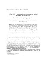
Figure 1.2 shows an example. The figure depicts both experimentally measured
dielectric constant (circular symbols) and its fit to a Drude-like formula (solid lines).
As we can see, the agreement is quite good. Later on (e.g. in Chap. 2)wewillseethat
in order to express accurately the dielectric constant of some metals, additional terms
are needed. For the moment, the Drude model contains all t he elements required for
illustrating the next discussion.
Therefore, if ε
I
(= ε) is a real positive number and ε
II
= ε
m
, where the subscript
“m” states for metals, Eqs. 1.6 and 1.7 define the propagation properties of SPPs.
Figure 1.3 represents the dispersion relation of SPPs on the air-silver interface,
where the dielectric constant of silver has been modeled with the Drude parameters
appearing in Fig. 1.2. As expected, beyond certain energy values the SPP dispersion
relation is clearly distinguished fromthe light line, a feature due to its intrinsic evanes-
cent character. The anomalous dispersion observed at high frequencies is due to
absorption. For lossless metals an asymptotic regime is reached at large wave-vector
values. In fact, the SPP frequency tends to ω
p
/
√
1 + ε
r
if the damping coefficient γ
is set to zero for the Drude model (Eq. 1.10).
Hereafter we will take a general assumption that is useful for good metals (Ag,
Au, Cu), namely that |ε
m
|ε
m
(ε
m
= ε
m
+ ıε
m
), so ε
m
≈ ε
m
. There are other
metals (Al, Ni, Co, Cr, Pb ) for which this approximation is no longer valid, as we
will see. In some cases, the condition |ε
m
|ε is a good approximation as well.
The properties defining a SPP come from its dispersion relation and the z-
component of the
k-vector. These properties tell us what is the spatial “period”
of a SPP, how long it takes before being absorbed, and how confined a SPP is inside
and outside the metal surface (For a review see [11]). The SPP wavelength is defined
as follows,
λ
SPP
=
2π
Re(k
SPP
)
(1.11)
1.1 Electromagnetic Fields Bound to Metals: Surface Plasmon Polaritons 5
Fig.1.2 For silver: a Re[ε
m
]
b Im[ε
m
]. Circular symbols
render experimental data
[10]. Solid lines fit the
experiments to a Drude-like
formula, defined by the
parameters shown in a
(a)
(b)
Fig.1.3 SPP dispersion
relation for silver (solid line)
fitted into a Drude-like
formula. We use the
parameters shown in Fig. 1.2.
The dashed line renders the
light cone
For good metals, it can be approximated by:
λ
SPP
= λ
0
ε + ε
m
εε
m
(1.12)
where λ
0
is the wavelength in vacuum
ω
c
=
2π
λ
0
. It is easy to see that λ
SPP
<λ
0
,
which it is another consequence of the singular dispersion relation of SPPs (See
Fig. 1.3).
6 1 Introduction
The length at which the energy carried by a SPP has decayed a 1/e factor is called
absorption length and is defined as
L
abs
=[2Im(k
SPP
)]
−1
(1.13)
Again, we can make use of the approximation for good metals to obtain
L
abs
= λ
0
(ε
m
)
2
2πε
m
ε + ε
m
εε
m
3
2
(1.14)
If |ε
m
|ε, the last formula can be further approximated leading to
L
abs
= λ
0
(ε
m
)
2
2πε
m
(1.15)
This result means that metals with a large (negative) real part of the relative
permittivity are better for guiding or for resonant processes (which require long time
to occur). It clearly shows the role played by the damping factor of metals in the SPP
behavior: L
abs
→∞when the imaginary part of the dielectric constant (ε
m
) tends
to zero, i.e., as the damping goes to zero too.
Interestingly, for good metals the SPP electric field is primarily transverse in the
dielectric and longitudinal in the metal, as the following expressions demonstrate,
|E
ε
z
|=
|ε
m
|
ε
|E
x
|, |E
m
z
|=
ε
|ε
m
|
|E
x
| (1.16)
showing the hybrid nature of SPPs that combines the features of both propagating EM
waves in dielectrics and free electron oscillations in metals. Since the SPP damping
occurs due to ohmic losses (∼
j
E), which in metals is related to the charge current
(
j) induced by the SPP fields, it is the longitudinal electric field component (E
x
) of
the SPP in the metal that determines absorption.
It is worth defining another magnitude which can deliver useful information about
the SPP nature: the penetration of the SPP fields into each medium. In the dielectric
half-space it takes the form δ
ε
=[Im(k
ε
z
)]
−1
and in the metal, where it is called skin
depth δ
m
=[Im(k
m
z
)]
−1
. For lossless metals, skin-depth formulas can be rewritten
in a compact manner,
δ
m
≈
λ
2π
|ε
m
|
δ
ε
≈
|ε
m
|λ
2πε
(1.17)
The penetration depth of the field into the dielectric gives us a measure of the
length scale over which the SPP mode is sensitive to the presence of changes in
refractive index, for example the presence of certain bio-molecules in a biosensor.
1.1 Electromagnetic Fields Bound to Metals: Surface Plasmon Polaritons 7
If we substitute in Eq. 1.17 the expression of ε
m
using the Drude formula (γ ∼ 0),
and noting that we are working well below the plasma frequency (ω ω
p
) one
obtains for the penetration length into the dielectric
δ
ε
=
λ
2
2πελ
p
δ
m
=
λ
p
2π
(1.18)
where ω
p
= 2π/λ
p
. Values for ω
p
are around ∼9 eV, i.e., λ
p
∼ 137.7nm,soin
this case, the confinement of a SPP could be considered subwavelength up to ∼865
nm, since δ
ε
<λfor shorter wavelengths. On the other hand, it is interesting that
the penetration depth in metals depends rather weakly on the wavelength, staying
at the level of a few tens of nanometers (δ
m
∼ 22 nm), while that in dielectrics
increases fast and nonlinearly with the wavelength. The penetration depth into the
metal gives us a measure on the required metal thickness that allows coupling to freely
propagating light in the prism coupling (Kretschmann) geometry (typically 50 nm
for silver and gold in the visible). It also sets the length scale of the film thickness
so that direct transmission through the film occurs. Moreover, the skin depth gives
information about the coupling strength between SPPs at opposite sides of the film.
The penetration depth into metals also gives us an idea of the feature sizes needed to
control SPPs: as features become much smaller than the penetration depth into the
metal they will have a diminishing effect on SPP modes. In SPP investigations, the
small-scale (nm) roughness is associated with many of the fabrication techniques
that create the metal films. Due to this, a minor perturbation to the SPP mode is
provided.
All these quantities (λ
SPP
, L
abs
,δ
m
,δ
ε
) have been represented in Fig. 1.4 for two
different metals: silver [panels (a) and (b)] and nickel [Panels (c) and (d)]. Nickel is
considered a “bad” metal due to the huge imaginary part of its dielectric constant.
We can observe for both metals that at long wavelengths λ
SPP
→ λ
0
,asEq.1.12
predicts. As we said, the imaginary part of ε
m
is greater for Ni than for Ag, which
explains the differences between the calculated values of L
abs
. Nevertheless their
skin depths are similar. As the figure clearly shows, the approximations that have led
to approximated values for δ
m
and δ
ε
are no longer valid in the case of “bad” metals,
as one could expect.
1.2 The Finite-Difference Time-Domain Method
1.2.1 The FDTD Algorithm
The finite-difference time-domain (FDTD) method belongs to the general class
of grid-based differential time-domain numerical methods. The time-dependent