steinmetz cp on the law of hysteresis part 3
Bạn đang xem bản rút gọn của tài liệu. Xem và tải ngay bản đầy đủ của tài liệu tại đây (5.59 MB, 47 trang )
A4
.,a
er
presented
at
tfle
Eleventh
General
Meetizg
of
the
Amee
rican
Institute
of
Electrical
Eng-in
eers,
Philadelfhlia,
May
i8th,
1894,
President
Hcnston
in
the
Choir
'
ON
THE
LAW
OF
HYSTERESIS
(PART
III.),
AND
THE
THEORY
OF
FERRIC
INDUCTANCES.
BY
CHARLES
PROTEUS
STEINMETZ.
CHAPTER
I COEFFICIENT
OF
MOLECUTLAR
MAGNETIC
FRICTION.
In
two
former
papers,
of
January
19
and
September
2T,
1892,
I
have
shown
that
the
loss
of
energy
by
mnagnetic
hysteresis,
due
to
miolecular
friction,
can,
with
sufficient
exactness,
be
expressed
by
the
empirical
formula-
:I
=
a
B16
where
H
=
loss
of
energy
per
cm3.
and
per
cycle,
in
ergs,
B
=
amplitude
of
magnetic
variation,
coefficient
of
molecular
friction,
the
loss
of
energy
by
eddy
currents
can
be
expressed
by
h
_1N
B2,
where
h
=
loss
of
energy
per
cm3.
and
per
cycle,
in
ergs,
z
coefficient
of
eddy
currents.
Since
then
it
has
been
shown
by
lMr.
R.
Arno.
of
Turiin,
that
the
loss
of
energy
by
static
dielectric
hysteresis,
i.e.,
the
loss
of
energy
in
a
dielectric
in
an
electro-static
field
can
be
expressed
by
the
same
formula:
H=
aF
where
R
=
loss
of
energy
per
cycle,
F
=
electro-static
field
intensity
or
initensity
of
dielectric
stress
in
the
material,
a
=
coefficient
of
dielectric
hysteresis.
Here
the
exponent
2
was
found
approximately
to
=
1.6
at
the
low
electro-static
field
intensities
used.
At
the
frequencies
and
electro-static
field
strengths
met
in
570
ÆTHERFORCE
1894.]
S'EINYMETZ
ON
HYSTERESIS.
571
condensers
used
in
alternate
current
circuits,
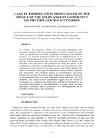
I
found
the
loss
of
energy
by
dielectric
hysteresis
proportional
to
the
square
of
the
field
strength.
Watts
-24,000-
_
___
_
_
_
__
___
-2-2-7000
-2-0
000-
_
_
.
_
_
___.
_
-1
00-
-,C
__
___
-47000-
___
____.
__
_____
-1-2-,00-0-
-_
_
40-,000
8TOGO
-
0
-000-
_
-4-,000
___
-27-00
0
Volts
2,000
3,000
4,000
5,000
6,000
7,000
8,000
9,000
Bradley/
&
PoatZes,
Enar'>s,
N.
Y.
FIG.
1.
Other
observations
made
afterwards
agreed
with
this
result.
With
regard
to
magnetic
hysteresis,
essentially
new
discoveries
ÆTHERFORCE
572
STEINMETZ
ON
HYSTERESIS.
[May
18,
have
not
been
mnade
sinTce,
and
the
explanation
of
this
exponent
1.6
is
still
unknown.
In
the
calculation
of
the
core
losses
in
dynamo
electrical
ma-
chinery
and
in
transformers,
the
law
of
hysteresis
has
found
its
applicationa,
and
so
far
as
it
is
not
obscured
by
the
superposition
of
eddy
currents
has
been
fully
confirmied
by
practical
experi-
ence.
%
As
anl
instance
is
slhown
in
Fig.
1,
the
observed
core
loss
of
a
high
voltage
500
E.
w.
altornate
current
generator
for
power
transmissioni.
The
curve
is
plotted
with
the
core
loss
as
abscisse
and
the
ter-minal
volts
as
ordinates.
The
observed
values
are
marked
by
crosses,
while
the
curve
of
1.6
power
is
shown
by
the
drawni
line.
The
core
loss
is
a
very
large
and
in
alternators
like
the
present
machine,
eveni
the
largest
part
of
the
total
loss
of
ener,gy
in
the
machine.
With
regard
to
the
numnerical
values
of
the
coefficient
of
hysteresis,
the
observations
up
to
the
time
of
my
last
paper
cover
the
range,
97X
j03=
Materials
From
To
Average.
Wrought
iron,
Sheet
iron
and
sheet
steel
(
2.00
5.48
3.0
to
3.3
Cast
iron
11I3
T6.2
T3.0
Soft
cast
steel
and
mitis
metal
3.18
12
0
6.o
Hard
cast
steel
27.9
Welded
steel
.
2
e
I4.5
74.1
Magnetite
.
20.4
23.5
Nickel
2.2
38.5
Cobalt
"I.9
While
no
new
materials
lhave
been
investigated
in
the
mean-
timue,
for
some,
especially
sheet
iron
and
slheet
steel,
the
range
of
observed
value
of
i
has
been
greatly
extended,
and,
I
am
glad
to
state,
mostly
towards
lower
valuLe
of
-,
that
is,
better
iron.
While
at
the
time
of
my
former
paper,
the
value
of
hysteresis
X
10'
=
2.0,
talen
from
Ewing's
tests,
was
-unequaled,
and
the
best
material
I
could
secure,
a
very
soft
Norway
iron,
gave
d
X
l03-
2.275,
now
quite
frequently
vaiues,
considerably
better
than
Ewing's
soft
iron
wire
are
found,
as
the
following
table
shows,
which
gives
the
lowest
and
the
highest
values
of
hysteretic
loss
observed
in
sheet
iron
and
sheet
steel,
intended
for
electrical
maehiniery.
ÆTHERFORCE
1894.]
STEINMETZ
ON
HYSTERESIS.
573
The
values
are
taken
at
random
from
the
factory
records
of
the
General
Electric
Company.
Values
of
X
10O.
LIowest.
Highest.
1.24
5.30
1.33
5.15
1.35
5.12
1.58
4.78
1.59
4.77
1.59
4.72
1.66
4.58
1.66
4.55
1.68
4.27
1.70
1.71
1.76
1.80
1.82
1.88
1.90
1.93
1.94
1.94
As
seen,
all
the
values
of
the
first
column
refer
to
iron
superior
in
its
quality
eveni
to
the
sample
of
Ewing
^q
X
10
2.0,
unequaled
before.
The
lowest
valuie
is
^
X
10'
=
1.24,
that
is,
38
per
cent.
better
than
Ewing's
iron.
A
sample
of
this
iron
I
have
here.
As
you
see,
it
is
very
soft
material.
Its
chemical
analysis
does
not
show
anything
special.
The
chemical
constitution
of
the
next
best
samnple
j
X
10
=
1.33
is
almost
exactly
the
same
as
the
con-
stitution
of
samples
C
X
103
=
4.77
and
^
X
103
-
3.22,
show-
ing
quite
conclusively
that
the
chemical
constitution
has
no
direct
influenice
upon
the
hysteretic
loss'.
In
consequence
of
this
extenision
of
§
towards
lower
values,
the
total
range
of
C
yet
known
in
iron
and
steel
is
fromr
C
X
101
=
1.24
in
best
sheet
iron
to
q
X
10(
=
74.8
in
glass-
hard
steel,
and
a
X
108
81.8
in
manganese
steel,
giving
a
ratio
of
1
to
66.
With
regard
to
the
exponenit
X
in
H=a
B
which
I
found
to
be
approximnately
=
1.6
over
the
whole
range
of
magnetization,
Ewing
has
investigated
its
variation,
and
found
that
it
varies
somnewhat
at
different
magnetizationls,
and
that
its
variation
corresponds
to
the
shape
of
the
magnetization
curve,
showing
its
three
stages.'
1.
J.
A.
Ewing,
Philo8ophical
Transaections
of
the
Royal
Society,
London,
Juine
15,
1893.
ÆTHERFORCE
574
STE]NMETZ
0N
HYSTERESIS.
[May
18,
Tests
of
the
variation
of
the
hysteretic
loss
per
cvele
as
fune-
tion
of
the
temperature
have
been
published
by
Dr.
W.
Kunz',
for
temnperatures
from
20°
and
800°
Cent.
They
show
that
with
rising
temperature,
the
hysteretic
loss
decreases
very
greatly,
and
this
decrease
consists
of
two
parts,
one
part,
whieh
disap-
pears
againi
with
the
decrease
of
temiperature
and
is
directly
pro-
portional
to
the
increase
of
temperature,
thus
making
the
hyster-
etic
loss
a
linear
function
of
the
temperature,
anid
another
part,
which
has
becomne
permanent,
anid
seems
to
be
due
to
a
perma-
nent
ehange
of
the
m-olecular
structure
produced
by
heating.
This
latter
part
is
in
soft
iron,
proportional
to
the
temperature
also,
buit
irregular
in
steel.
CHAPTER
II MOLECULAR
FRICTION
AND
MAGNETiC
HYSTERESIS.
In
an
alternating
magnetic
circuit
in
iron
and
other
magnetic
material,
energy
is
converted
inito
heat
by
molecular
magnetic
friction.
The
area
of
the
hysteretic
loop,
with
the
AT.
MI.
F.
as
abscissse
and
the
magnetization
as
ordinates,
represents
the
energy
expended
by
the
M.
I.
F.
during
the
cyclic
ehange
of
magnetization.
If
energy
is
neitlher
consumed
nor
applied
outside
of
the
magnetic
circuit
by
any
other
souLrce,
the
area
of
the
hysteretic
loop,
i.
e.,
the
energy
consumed
bv
hysteresis,
mneasures
and
represents
the
energy
wasted
by
molecular
magnetic
friction.
In
general,
however,
the
energy
expended
by
the
M.
M.
F
the
area
of
the
hysteretic
loop-needs
not
to
be
equal
to
the
molecular
friction.
In
the
armature
of
the
dynamno
machine,
it
probably
is
not,
but,
while
the
hysteretic
loop
more
or
less
col-
lapses
under
the
influence
of
mechanical
vibrationi,
the
loss
of
energy
by
molecular
friction
remains
the
sa-me,
hence
is
no
longer
measured
by
the
area
of
the
hysteretic
loop.
Thus
a
sharp
distinction
is
to
be
drawn
between
the
phenome-
non
of
'magnetic
hysteresis,
which
represents
the
expenditure
of
energy
by
the
M.
M.
F.,
and
the
molecuilar
friction.
In
stationary
alternating
current
apparatus,
as
ferric
induc-
tances,
hysteretic
loss
and
inolecular
magn-etic
friction
are
generally
idenrtical.
In
revolving
machinery,
the
discrepancy
between
molecular
friction
and
magnetic
hysteresis
may
become
very
large,
and
the
magnetic
loop
may
even
he
overturhred
and
represent,
not
expen-
1.
eUtroteohni8che
Zeitschrift,
Arril
5th,
1894.
ÆTHERFORCE
1894.]
STEINMETZ
ON
HYSTERESIS.
575
diture,
but
production
of
electrical
energy
from
meebanical
energy;
or
inversely,
the
magnetic
loop
may
represent
not
only
the
electrical
energy
converted
into
heat
by
molecular
friction,
buLt
also
electrical
energy
converted
into
mechanical
miotion.
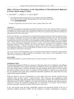
Two
such
cases
are
shown
in
Figs.
2
and
3
and
in
Figs.
4
and
Z
In
these
cases
the
magnetic
reluctance
and
thus
the
indue-
tance
of
the
circuit
was
variable.
That
is,
the
magnetic
circuit
was
opened
and
closed
by
the
revolution
of
a
shuttle-shaped
armature.
The
curve
s
represenits
the
inductan-ces
of
the
mnagnetic
circuit
_
E
_
Bradley
~Poates,
Enrs,
N.
Y.
FiG.
2.
as
function
of
the
position.
The
curve
a,
couLnter
E.
M.
F.
or,
since
the
internal
resistance
is
negligrible,
the
impressed
E.
M.
F.
and
curve
M
-_
magnetismn.
If
the
impressed
-E.
M.
F.,
E
iS
a
sine
wave,
the
current
c
assumes
a
distorted
wave
shape,
and
the
produict
of
current
anid
E.
M.
F_,
W
-C
E
represents
the
energy.
As
seen,
in
this
case
t-e
total
energy
is
not
equal
to
-zero,
i.
e.,
the
a.
M.
F.
or
self-induction
E
not
wattless
as
usually
supposed,
but
represe-nts
production
of
electr'ical
energy
in
the
-first,
conisumptlion
in
the
second
case.
Thus,
if
the
apparatus
is
driven
by
exterior
power,
it
assumes
the
phase
relation
shown
in
ÆTHERFORCE
576
STEINMETZ
ON
HYSTERESIS.
[May
18,
Fig.
2,
arid
yields
electrical
energy
as
a
self-exciting
alternate
current
generator;
if
now
the
driving
power
is
withdrawn
it
drops
into
the
phase
relation
shown
in
Fig.
4,
and
then
continues
to
revolve
and
to
yield
mechanical
energy
as
a
synchronous
motor.
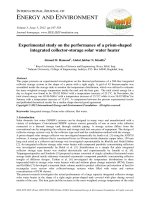
The
magnetic
cycles
or
H-B
curves,
or
rather
for
convenience,l
the
C-A
curves,
are
shown
in
Figs.
3
and
5.
As
seen
in
Fig.
5,
the
magnetic
loop
is
greatly
increased
in
area
and
represents
not only
the
energy
consumed
by
molecular
magnetic
friction,
but
also
the
energy
converted
into
mechaniical
power,
while
the
loop
in
Fig.
3
is
overturned
or
negative,
thus
representing
the
electrical
energy
produced,
minus
loss
by
molee-
ular
friction.
:
X_
-~~~~~
FIG.
3.
This
is
the
same
apparatus,
of
which
two
hysteretic
loops
were
shown
in
my
last
paper,
an
indicator-alternator
of
the
"hhummning
bird"
type.
Thus
magnetic
hysteresis
is
not
identical
with
molecular
mag-
netic
friction,
but
is
one
of
the
phenomrena
caused
by
it.
CHAPTER
III THEORY
AND
CALCULATION
OF
FERRJIC
INDIUCTANCES.
In
the
discussion
of
inductive
circuits,
generally
the
assump-
tion
is
made,
that
the
circuit
contains
no
iron.
Such
non-ferric
inductances
are,
however,
of
little
interest,
since
inductances
are
almost
always
ironclad
or
ferric
inductances,
ÆTHERFORCE
1894.1
STEINMETZ
ON
HYSTERESIS.
5
With
our
present
knowledge
of
the
alternating
magnetic
cir-
cuit,
the
ferric
inductances
can
now
be
treated
analytically
with
the
same
exactness
and
almost
the
same
siimplicity
as
non-ferrie
inductances.
Before
entering
into
the
discussion
of
ferric
inductances,
some
ternms
will
be
introduced,
which
are
of
great
value
in
simplify-
ing
the
treatinent.
Referrilig
back
to
the
continuous
current
circuit,
it
is
known
that,
if
in
a
continu-ous
current
circuit
a
number
of
resistances)
__
__
__
_te
__
__
_
_
_
_
_
A~~~~~
~
__
__
__X7
\
Bradley
'PoXates
Engrs,
N.Y.'
FIG.
4.
ri,
r2,
93
.
.
.
.
are
connected
in
series,
their
joint
resistance,
R,
is.
the
sum
of
the
individual
resistances:
R=
+
r2
+
r
+
*
If,
however,
a
number
of
resistances,
r
I
r
3.
.
.r,
are
con-
nected
in
parallel,
or
in
multiple,
their
joint
resistance,
R,
can-
not
be
expressed
in
a
simple
form,
but
is:
Hence,
in
the
latter
case,
it
is
preferable,
instead
of
the
tern
ÆTHERFORCE
578
STEINMIETZ
ON
HYSTERESIS.
[May
18,
4
resistance,"
to
introduce
its
reciprocal,
or
inverse
value,
the
term
i
conduetanee"
p
=
.
Theen
we
get:
"If
a
number
of
conlductanices,
pn
P2,
p3
.
are
connected
in
parallel,
their
joined
conductance
is
the
sum
of
the
inidividual
conductances:
p=
P
+
P2
+
p3
+
When
usilng
the
term
conductance,
tlhe
joined
conductance
of
t
=X
t
/
TfI
I+
_-M
Bradley
&
Poates,
EBgr',
N.
Y.
FIG.
5.
a
number
of
series
connected
conductances,
Pl
P2,
p3
.
becomes
a
complicated
expression
-P
Pt
P2
P's
Hence
the
use
of
the
termn
"resistance"
is
preferable
in
the
case
of
series
connection,
the
use
of
the
reciprocal
term.
con-
ductance,"
in
parallel
connection,
and
we
have
thus:
"The
joined
resistance
of
a
number
of
series
connected
re-
si
ts
ces
is
eqtal
to
the
sum
of
the
individual
resistances,
the
Joined
conductance
of
a
number
of
parallel
connected
conduct-
ances
is
equal
to
the
sum
of
the
individual
conduct
ances."
In
alternating
current
circuits,
in
place
of
the
term
"resist-
ÆTHERFORCE
1894.]
STEINMETZ
ON
HYSTERESIS.
579
ance"
we
hiave
the
term
"impedance,"'
expressed
in
comnplex
quantities
by
the
symbol:
U
r-J8
with
its
two
components,
the
"resistacie"
r
and
the
"react-
ae
s,
in
the
formula
of
Ohm's
law:
E=
C
U.'
The
resistance,
r,
gives
the
coefficient
of
the
E.
M.
F.
in
phase
with
the
current,
or
tlhe
energy
component
of
E.
M.
F.,
Cr;
the
reactance,
s,
gives
the
coefficient
of
the
E.
M.
F.
in
quadrature
with
the
current,
or
the
wattless
CoMponent
of
E.
M.
F.,
Cs,
botl
combined
give
the
total
E.
M.
F.
CW=
C
Vr
+s2
Thlis
reactance,
S,
is
positive
as
inductive
reactance:
s
_
2
wr
Nl,
or
negative
as
capacity
reactance:
s
2
7r
NK'
where,
N
=
frequency,
I
=
coefficient
of
self-induction,
in
h-enrys,
X
=
capacity,
in
farads.
Since
F.
M.
F.'s
are
combined
by
adding
their
complex
expres-
sions,
we
hlave:
"'The
joinied
impedance
of
a
numiiber
of
series
connected
im-
pedances,
is
the
sum
of
the
individual
impedances,
when
ex-
pressed
in
complex
quantities."
In
graphical
representation,
impedances
have
not
to
be
added,
but
combined
in
their
proper
phase,
by
the
law
of
parallelogram,
like
the
1.
M.
F.'S
consumed
by
them.
The
termn
'4
impedance
"
becornes
inconvenienlt,
hiowever,
when
dealinig
with
parallel
connected
circuits,
or,
in
other
words,
when
several
currents
are
produced
by
the
same
E.
M.
F.,
in
cases
where
Ohm's
law
is
expressed
in
the
form:
It
is
preferable
then,
to
introduce
tlhe
reciprocal
of
"impe-
1.
"
Complex
Quantities
and
their
use
in
Electrical
Engineering,'"
a
paper
read
before
Section
A
of
the
Initernational
Electrical
Congress
at
Chicago,
1893.
ÆTHERFORCE
580
STElNAETZ
ON
HYSTERESIS.
[May
18,
dance,"
which
may
be
called
the
"
admittance"
of
the
circuit:
F_1
As
the
reciprocal
of
the
complex
quantity
U
=
r
-j8,
the
admittanee
is
a
complex
quantity
also:
Y
p
+-J
H
consisting
of
the
component,
p,
which
represents
the
coefficient
of
current
in
phase
with
the
E.
M.
F.,
or
energy
current,
o
E,
in
the
equation
of
Ohm's
law:
C
=
YE(p
+j
a)
E,
and
the
component,
CTwhich
represents
the
coefficient
of
current
in
quadrature
with
the
E.
M.
F.,
or
wattless
component
of
current,
arE.
p
may
be
called
the
"
condcetance,"
a
the
"suseeptance"
of
the
eirculit.
Hence
the
conductance,
p,
is
the
energy
component,
the
susceptance,
?,
the
wattless
component
of
the
admnittance
Y
y
+i
n
anid
the
nLmerical
value
of
admittanee
is:
v=
the
resistance,
r,
is
the
energy
component,
the
reactance,
8,
the
wattless
component
of
the
impedance
U
r
-
-J
8r
and
the
numerical
value
of
impedance
is
e
sl
u
=
t/r2
+
8'2.
As
seen,
the
term
"
admittance
"
means
dissolving
the
current
into
two
components,
in
phase
and
in
quadrature
with
the
E.
M.
F,,
or
the
energy
current
and
the
wattless
current;
while
the
term
"'
impedance"
means
dissolving
the
F.
M.
F.
into
twp
coimponents,
in
phase
and
in
qluadrature
with
the
curreint,
or
the
energy
E.
M.
F.
and
the
wattless
E.
M.
F.
It
must
be
understood,
however,
that
the
"conductance"
is,
not
the
reciprocal
of
the
resistance,
but
depends
upon
the
resist-
ance
as
well
as
upon
the
reactance.
Only
when
the
reactance
s
-
0,
or
in
continuous
current
circuits,
is
the
conductance
the
reciprocal
of
resistance.
Again,
only
in
circuits
with
zero
resistance
-
=
0,
is
the
sus-
ÆTHERFORCE
1894.]
STEIN
ETZ
ON
HYSTERESIS.
581
ceptance
the
reciprocal
of
reactance;
otherwise
the
susceptance
depends
upon
reactance
and
upon
resistance.
From
the
definition
of
the
admnittance:
Y
=p
+j
a
.as
the
reciprocal
of
the
impedance:
U=
r-j8
we
get
Y1
or
1
P
+j
q
=
-a
or,
multiplying
on
the
right
side
numerator
and
denominator
by
!(r
+js):
+j
(r-j
8)
(r
+j
8)'
hence,
since
(r
j
s)
(P
+j
8)
=
r2
+
82
=
2:
r
8
.
S
r
+
S
Y/+8S2
u2
+
u78
or,
P
2
r
+
-
g
and
inversely:
t_
P
-2+
2
v2
C
_
C
S=
2
+
ve
2
By
these
equations,
from
resistanee
and
reactanee,
the
conduct-
ane
and
susceptance
can
be
calculated,
and
inversely.
Multiplying
the
equations
for
p
and
r,
we
get:
?rp
Pr
t2
2,1
lav
hence,
,2
2
(r2
+
82)
(p2
+
?)
=
1
and
1
1
;
U
=
-
ÆTHERFORCE
:582
STEINMETZ
0N
HYSTERESIS.
[May
18,
the
absolute
value
of
impedance,
iL
1
u
4
r2
+
S2
the
absolute
value
of
admittance.
The
sign
of
"
admittance
"
is
always
opposite
to
that
of
"im-
pedance,"
that
means,
if
the
cuirrent
lags
behind
the
E.
M.
F.,
the
E.
M.
F.
leads
the
current,
and
inversely,
as
obvious.
Thus
we
can
express
Ohm's
law
in
the
two
forms:
h'
=
U.
C=E
Y,
and
have
"T
The
joined
impedance
of
a
number
of
series
connected
im-
pedlances
is
equal
to
the
sum,
of
the
individual
impedances;
the
joined
admittance
of
a
number
of
parallel
connected
admittances
is
eqlual
to
the
sumn
of
the
individual
admittances,
if
expressed
in
complex
quantities;
in
diagramm,natic
representation,
com-
bination
by
the
parallelogram
law
takes
the_place
of
addition
of
the
complex
quantities."
The
resistance
of
an
electric
circuit
is
determined:
1.
By
direct
comparison
with
a
known
resistance
(Wheatstone
bridge
method,
etc.).
This
method
gives
what
may
be
called
the
truie
ohinic
resistance
of
the
circuit.
2.
By
the
ratio:
Volts
consuLmed
in
circuit
Amperes
in
circuit
In
an
alternating
current
circuit,
this
method
gives
not
the
re-
sistance,
but
the
impedance
u/
=
V'r2+
s2
of
the
circuit.
3.
By
the
ratio:
Power
consumed
-
(E.
M.
.)2
(current)2
Power
consumed'
where,
however,
the
"'power
"
and
the
"
E.
M.
F."
do
not
in-
elude
the
work
done
by
the
circuit,
and
the
counter
E.
M.
F.'S
representing
it,
as
for
instance,
the
counter
E.
N.
F.
of
a
motor.
In
alternlating
current
circujits,
this
value
of
resistance
is
the
energy
coefficient
of
the
E.
N.
F.,
and
is:
r
Eniergy
component
of
E.
M.
F.
Total
current
ÆTHERFORCE
1894.]
STEINMETZ
ON
HYSTERESIS.
583
It
is
called
the
"
equivalent
resistanc"
of
the
circuit,
and
the
energy
coefficient
of
current:
-
Energy
comnponent
of
current
Total
E,
M.
F.
is
called
tlle
"
equivalent
conductance"
of
the
circuit.
In
the
same
way
the
valie:
8
=
WattIess
component
of
E.
M.
F.
Total
current
is
the
"equivalent
reactance,"
and
Wattless
comnponent
of
current
Total
E.
M.
F,
is
the
"equivalen
t
8suceptance"
of
the
circuit.
While
the
true
ohmic
resistance
represents
the
expenditnre
of
energy
as
heat,
inside
of
the
electric
conductor,
by
a
current
of
uniform
deensity,
the
"
equivalent
resistance
"
represents
the
total
expenditure
of
energy.
Since
in
an
alternating
current
circuit
in
general,
energy
is
ex-
pended
nlot
only
in
the
conductor,
but
also
outside
thereof,
by
hysteresis,
secondary
currents,
etc.,
the
equivalent
resistance
fre-
quently
differs
from
the
true
ohmic
resistanee,
in
such
way
as
to
represent
a
larger
expendituire
of
energy.
In
dealing
with
alternating
current
circuits,
it
is
necessary,
therefore,
to
substitute
everywhere
the
values
"
equivalent
resist-
ance,"
"equivalent
reactance,"
"equivalent
conductance,"
"equivalent
susceptance,"
to
iiiake
the
calculation
applicable
to
genaeral
alternating
current
circuits,
as
ferric
inductance,
etc.
While
the
true
ohmic
resistance
is
a
conistant
of
the
circuit,
depending
upon
the
temuperature
only,
but
not
upon
the
E.
M.
F.e
etc.,
the
"'equivalent
resistance"-
and
"equivalent
reactanee"
is
in
general
not
a
constant,
but
depends
upon
the
E.
M.
F.,
cur-
relt,
etc.
This
depenidence
is
the
cause
of
most
of
the
difficulties
mret
in
dealing
analytically
with
alternating
cuLrrent
circuits
containing
iron.
The
foremost
sources
of
energy
loss
in
alternating
current
cir-
cuits,
oLutside
of
the
true
ohmic
resistance
loss,
are:
1.
Molecular
friction,
as:
(a)
magnietic
hysteresis;
(b)
dielectric
hysteresis.
ÆTHERFORCE
M84
STEINMETZ
OJV
HYSTERESIS.
[May
18,
2.
Primary
electric
currents,
as:
(a)
leakage
or
escape
of
cuLrrent
through
the
insulation,
brush
discharge;
(b)
eddy-eurrents
in
the
conductor,
or
unequal
current
distribution.
3.
Secondary
or
induced
currents,
as:
(a)
eddy
or
Foucault
currents
in
surrounding
miagnetic
materials;
(b)
eddy
or
Foucault
currents
in
surroundino,
conducting
materials;
(e)
secondary
currents
of
mutual
inductanlce
in
neighbor-
ing
circuits.
4.
Induced
electric
charges,
electro-static
influence.
While
all
these
losses
can
be
included
in
the
terms
"1
equivalent
-resistance,"
etc.,
only
the
magnetic
hysteresis
and
the
eddy-cur-
rents
in
the
iron
will
form
the
object
of
the
present
paper.
I Alfaynetic
IJsteresi.S.
To
examinle
this
phenomenon,
first
a
cireuit
of
very
high
in-
ductanee,
but
negligible
true
ohmic
resistance
may
be
considered,
that
is,
a
circuit
entirely
surrounded
by
iron
;
for
iiistance,
the
primary
circuit
of
an
alternating
current
transformer
with
open
secondary
circuit.
The
wave
of
current
produces
in
the
iron
an
alternating
mag-
netic
flux,
which
induces
in
the
electric
eireuit
all
.
M.
F.,
the
,counter
E.
M.
F.
of
self-induction.
If
the
ohmic
resistance
is
negligible,
the
counter
E.
M.
F.
equals
the
impressed
E.
M.
F.,
hence,
if
the
impressed
.
M.
F.
is
a
sine-wave,
the
counter
E.
M.
F.,
and
therefore
the
magnetism
which
induces
the
counter
F.
M.
F.
must
be
sine-waves
also.
The
alternating
wave
of
current
is
not
a
sine-wave
in
this
case,
but
is
distorted
by
hysteresis.
It
is
pos-
sible,
however,
to
plot
the
current
wave
in
this
case
from
the
hysteretic
eycle
of
magnetization.
From
the
number
of
turns
n
of
the
electric
circuit,
the
effective
couniiter
E.
M.
F.
L
and
the
frequenley
X
of
the
current,
the
max-
imum
magnetic
flux
M1
is
found
by
the
formula:
E=
4/2Nit
XX10;
hence:
M
E
10V
4/2
7t
fl
N
ÆTHERFORCE
1894.]
STEINYMETZ
ON
HYSTERESIS.
585
Maximum
flux
X1
anid
magnetic
cross-section
S
give
the
max-
31
imumn
magnetic
induction
B
If
the
miagnetic
induction
varies
periodically
between
+
B
and
-
B,
the
m.
M.
F.
varies
between
the
corresponding
values
+
Fand
-
F
and
describes
a
looped
curve,
the
cycle
of
hys-
teresis.
If
the
ordinates
are
given
in
lines
of
nmagnetic
force,
the
ab-
.
r16,00
0
4-___
14
00
_-
E__
m 12-0-
04
,000
-
-
-
,0
W
-L
-
/ 2
00
.
B
_
_____
_f2
C10
+0
4-
+10
44
4-10
-8
4_20
IL
/,040
.__
.1-
__
_
_
__
__
__
L-
:14000
Bradley
4
Poates,
Bgr'e,
N.
Y.
FIG.
6.
Scissoe
in
tens
of
ampere-turns,
the
area
of
the
loop
equals
the
energy
consumed
by
hysteresis,
in
ergs
per
cycle.
From
the
h-ysteretic
loop
is
found
the
instantaneous
value
of
M.
M.
F.
corresponding
to
an
instantaneous
value
of
magnetic
flux,
that
is
of
induced
E.
M.
F.,
and
from
the
m.
M.
F.,
F,
in
ampere-
tuLrns
per
unit
lenigth
of
magnetic
circuit,
the
length
I
of
the
magnetic
circuit,
and
the
number
of
turns
n
of
the
electric
cir-
cuit,
are
found
the
iiistantaneons
values
of
current
c
correspond-
ing
to
a
M.
M.
F.
F,
that
is
a
magnetic
induction
B
anld
thus
in-
duiced
E.
M.
F.
e,
as:
n
ÆTHERFORCE
586
STEINMETZ
ON
HYSTERESIS.
[May
18,
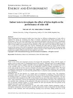
In
Fig.
6
four
magnetic
cycles
are
plotted,
with
the
maximumlh
values
of
magnetic
inlductions:
B
=
2,000,
6,000,
10,000
and
16,000,
and
the
corresponding
maximuM
M.
M.
F.'S:
F=
1.8,
2.8,,
4.3,
20.0.
They
show
the
well-known
h-ysteretic
loop,
which
be-
conies
pointed
when
magnetic
saturation
is
approached.
These
magnetic
cycles
correspond
to
average
good
sheet
iron
or
sheet
steel
of
hysteretic
coefficient:
.0033,
aind
are
given
0
F
B
2000
__
_
____
a
600
i1=
7
i
9
\
.8X
F
2.8
_
1-
W
__
_.1
i.
Ct~~~~0
-2.bl
Bradley
Poates,
Engr'8,
N.Y.
with
ampere-turns
per
cmi.
as
abscissoe
and
kilolinies
of
mnagnetic~
force
as
ordinates.
In
Figs.
7,
8,
9
and
10
the
mnagnetism,
or
rather
the
magnetic,
induction,
as
derived
from
the
i-nduced
'E.
M.
F.1
is
assumed
as,
sine-curve.
For
the
ditfer-ent
values
of
magnetic
inductioni
of'
this
sine-curve,
the
corresponding
values
of
m.
m.
F.~
hence
of~
c-urrent,
are
taken
from
Fig.
6,
a-nd
plotted,
givi-ng
thius
the
ex-
cit'ing
currenit
required
to
produce
the
si-ne-wave
of
miagnetism;
ÆTHERFORCE
1894.]
STEINf2TETZ
ON
HYSTERESIS.
587
that
is,
the
wave
of
current,
which
a
sine-wave
of
impressed
E.
M.
F.
will
send
through
the
circuit.
As
seen
fromn
Figs.
4
to
10,
these
waves
of
alternating
current
F
are
not
sine-waves,
but
are
distorted
by
the
superposition
of
higlher
harmonies,
that
is,
are
complex
harmonic
waves.
They
reach
their
maxinmum
value
at
the
same
tiimne
with
the
maximum
of
magnetism,
that
is,
900
ahead
of
the
naximum
induced
E.
M.
F.,
hence
about
90°
behind
the
maximum
impressed
E.
M.
F.,
but;
pass
the
zero
line
considerably
ahead
of
the
zero
valule
of
mag-
netismu:
42,
.52,
50
and
41
degrees
respectively.
The
general
character
of
these
curtrent
waves
is,
that
the
maax-
imum
point
of
thle
wave
coincides
inL
timne
with
the
maximumn
point
of
the
sine-wave
of
mlagnetism,
but
the
current
wave
is
bulged
out
greatly
at
the
risinlg;
hollowed
in
at
the
decreasing
side.
With
increasing
mnagnetization,
thle
maxsimum
of
the
current
ÆTHERFORCE
-388
STEINMETZ
ON
HYSTERESIS.
[May
18,
wave
becomes
more
pointed,
as
the
curve
of
Fig.
9,
for
B
=
10,000
shows,
and
at
still
higher
saturation
a
peak
is
formed
at
the
max-
imum
point.
as
in
the
curve
of
Fig.
10,
for
B
-
16,000.
This
is
the
case,
when
the
cuarve
of
magnetization
reaches
within
the
range
of
magnetic
saturation,
since
in
the
proximity
of
saturation
FiFiq.
11
-
1-\7
_
_
tl
T
W<<1t
;X.
I.
-_
1<
I
X~~~~~-
V7
/~
~
.~~~~~4
/X
-
-
-4-I
-
'
_r
rT
I
_
Bradley
Poates,
Engrls,
NJ.
the
current
near
the
nmaximum
point
of
magnetization
has
to
rise
abnormally,
to
cause
a
small
increase
of
magnetization
only.
The
distortion
of
the
wave
of
magnetizing
current
is
so
large
as
shown
here,
onlv
in
an
iron
closed
magnetic
circuit
expending
energy
by
hysteresis
ornly,
as
in
the
ironclad
transformer
at
open
ÆTHERFORCE
1894.]
STEINMETZ
ON
HYSTERESIS.
M8
secondary
circuit.
As
soon
as
the
circuit
expends
energy
in
any
other
way,
as
in
resistance,
or
by
mutual
inductance,
or
if
an
air-
gap
is
introduced
in
the
magnetic
circuit,
the
distortion
of
the-
current
wave
rapidly
decreases
and
practically
disappears,
and
the
current
beconles
more
sinuLsoidal.
That
is,
while
the
distort-
ing
component
rem-ains
the
same,
the
sinusoidal
component
of
current
greatlv
increases,
and
obscures
the
distortion.
For
in-
stance,
in
Figs.
11
and
12
two
waves
are
shown,
corresponding
in
mnagnetization
to
the
curve
of
Fig.
8,
as
the
worst
distorted.
The
curve
in
Fig.
11
is
the
current
wave
of
a
transformer
at
1
load.
At
higher
load
the
distortion
is
still
correspondingly
less.
The
curve
of
Fig.
12
is
the
exciting
current
of
a
magnetic
cir-
cuit,
containing
an
air-gap,
whose
length
equals
.1
the
lenigth
of
the
magnetic
circuit.
These
two
curves
are
drawn
in
3
the
size
of
the
curve
in
Fig.
S.
As
seen,
both
curves
are
practically
sine-waves.
The
distorted
wave
of
current
can
be
dissolved
in
two
com-
ponents:
a
true
sine-wave
of
equal
efective
intensity
and
equal
power
wit1l
the
distorted
wave,
called
the
"equivalent
sine-wave,"
and
a
wattless
hAiher
harmonic,
consistinig
chiefly
of
a
term
of
trip]e
frequiency.
In
Figs.
7
to
12
are
shown,
in
drawn
linaes,
the
equ:ivalent
sine-
waves,
and
the
wattless
complex
higher
harmonics,
whlich
together
formri
the
distorted
current
wave.
The
equivalent
sinle-wave
of
M.
M.
F.,
or
of
ecurrent,
in
Figs.
7
to
10,
leads
the
magnetism
by
34,
44,
38
and
15.5
degrees
respectively.
In
Figs.
11
and
12
the
equivalent
sine-wave
almost
coincides
with
the
distorted
curve,
and
leads
the
magnetism
by
only
90,
It
is
interesting
to
note,
that
even
in
the
oreatly
distorted
curves
of
Figs.
7
to
9
the
maximum
valne
of
the
equivalent:
sine-wave
is
nearly
the
same
as
the
maximuin
value
of
the
original
distorted
wave
of
M.
m.
ia.,
as
long
as
magnetic
saturationi
is
not
approached,
being
1.8,
2.9
and
4.2
respectively,
agaim
st
l.8,
2.8
and
4.3
as
inaximnuin
values
of
the
distorted
curve.
Since
by
the
definition
the
effective
valuLe
of
the
equivalent
sine-wave
is
the
same
as
that
of
the
distorted
wave,
this
meanis,
that
the
distorted
wave
of
exciting
current
shares
with
the
sine-wave
the
feature,
that
the
maximn-um
value
and
the
effective
value
h-iave
the
ratio:
4/2
+
1.
Hence,
below
saturation,
the
inaxim-num
value
of
tlhe
distorted
curve
can
be
calculated
from
the
effective
value-wlmieh
is
given
by
the
reading
of
an
electro-dynamometer-by
the
same
ratio
as
ÆTHERFORCE
:<590
STEIN1XETZ
ON
HYSTERESIS.
[May
18
with
a
true
sine-wave,
and
the
mlagnetic
characteristic
can
thus
be
determined
by
means
of
alternating
currents,
by
the
electro-
dynamometer
method,
witlh
su-fficient
exactness.
In.
Fig.
13
is
shown
the
truie
magnetic
characteristic
of
a
sample
of
average
good
sheet
iron,
as
found
by
the
metthod
of
slow
14
tr4-1X
;
<
-
-
X
i
3~~~~~~~~~~~~~~~~~~~~~~~rde
r,
Poaes
Enql,N.Y
'~~~~~~~~_
__
_
__
lii
/
1si5
tt_
Ii__
iiii-__
I__
12
X1
__
1
__
-
-reversals
by
the
magnetomueter,
and
for
coi-nparisoir
in
dotted
-lines
the
saiine
el-aracteristic,
as
determined
by
alternating
cur
rents,
by
the
electro-dynai-nometer,
with
amnpere-t-urris
per
cm.
as
ordinates,
and
magnetic
inductio-ns
as
abscissoe.
As
seen,
the
-two
c,urves
practically
coin2ide
up
to
9B
=
10,000
1
,14,000
.
ÆTHERFORCE
1894.]
STEINMIETZ
ON
HYSTERESIS.
591
For
higher
saturations,
the
curves
rapidly
diverge,
and
the
electro-dynamnometer
curve
shows
comparatively
small
M.
M.
F.S
s
producing
apparently
very
high
magnetizations.
The
sane
Fig.
13
gives
the
curve
of
hysteretic
loss,
in
ergs
per
cm.3
and
cycle,
as
ordinates,
and
magnetic
inductions
as
abscisse.
So
far
as
current
strength
and
energy
consumption
is
coneerned,
the
distorted
wave
can
be
replaced
by
the
equivalent
sine-wave,
and
the
higher
harimonies
nleglected.
All
the
measurements
of
alternating
currents,
with
the
only
exception
of
instantaneous
readings,
yield
the
equivalent
sine-wave
only,
but
snppress
the
higher
harmonic,
since
all
mneasuring
in-
struments
give
either
the
mean
square
of
the
cuirrent
wave,
or
the
mean
product
of
inistantaneous
values
of
current
and
E.
M.
F.
which
are
by
definition
the
same
in
the
equivalent
sine-wave
as
in
the
distorted
wave.
Hence,
in
all
practical
applications,
it
is
permissible
to
neglect
the
higher
harmonic
altogether,
and
replace
the
distorted
wave
by
its
equivalent
sine-wave,
keeping
iu
minid,
however,
the
existence
of
a
higher
harmonic
as
a
possible
disturbing
factor,
wicth
may
become
noticeable
in
those
very
infrequLent
cases,
where
the
fre-
quency
of
the
higher
harinonic
is
near
the
frequency
of
resonance
of
the
circuit.
The
equivalent
sine-wave
of
exciting
current
leads
the
sine-
wave
of
magnetismn
by
an
angle
a,
which
is
called
the
"
angle
of
Aysteretic
advance
of
phase."
Hence
the
current
lags
behind
the
E.
M.
F.
by
90
-
a,
and
the
power
is,
therefore:
P
=
CL
ecos
(90°-
a)
=
C
Esin
a.
Thus
the
execiting
current
C
consists
of
an
energy
comuponent:
C
sin
a,
-which
is
called
the
"
hy.3teretic
energy
current,"
and
a
wattless
component:
C
cos
a,
which
is
called
the
"mnagnetizing
eurrent."
Or
inversely,
the
E.
M.
F.
consists
of
an
energy
com-
ponent::
E
sin
a,
the
"hysteretic
envergy
E.
M.
F."
anid
a
wattless
component:
EGcos
a,
the
E.
m.
F.
of
self-rnductton."
Denoting
the
absolute
value
of
the
impedance
of
the
eircuit
by
u-where
u
is
determined
by
the
magnetic
characteristic
of
the
iron,
and
the
shape
of
the
magnletic
and
electric
circuit-the
impedance
is
represented,
in
phase
and
intensity,
by
the
synmbolic,
expression:
U
r-j
s
=
u
sin
a-j
u
Cos
a,
ÆTHERFORCE
592
STEINMETZ
ON
HYSTERESIS.
LMay
18.1
and
the
adimittance
by:
C
+
os
a
=
v
sin
a
+
C
I
cos
a.
The
quantities:
u,
r,
s
and
v,
p,
a
are
not
constanits,
however,
in
this case,
as
in
the
circuit
without
iron,
but
depend
upon
the
intensity
of
magnetization,
B,
that
is,
upon
the
E.
M.
F.
This
dependence
comnplicates
the
in-vestigation
of
circuits
con-
taining
iron.
In
a
eirenit
entirely
enelosed
by
iron,
a
is
quite
considerable,
from
30
to
50
degrees
for
values
below
saturation.
Hence
even
with
negligible
true
ohmic
resistance
no
great
lag
can
be
pro-
dueed
in
ironclaCl
alternating
current
irculits.
As
I
have
proved,
the
loss
of
energy
by
hysteresis
due
to
molecular
friction
is
with
sufficient
exactness
proportional
to
the
l.6th
power
of
magnetic
induction,
B.
Hence,
it
can
be
ex-
pressed
by
the
formula:
15
~B16,
where
AI=
loss
of
energy
per
cycle,
in
ergs
or
(c.
G.
S.)
units
(-
10-
Joules)
per
cm.,
B
=
maximnum
magnetic
induction,
in
lines
of
force
per
cm.',
and,
=
the
c
coefficient
of
hysteresis."
At
the
frequency,
N,
in
the
volume,
VT,
the
loss
of
power
is
by
this
formnula:
P
=
N
FB
-B'
10-7
watts,
-
N
V
(
1)0-7
watts,
where
8
is
the
cross-section
of
the
total
magnetic
flux,
Xl.
The
maximum
magnletic
flux,
Mf,
depends
upon
the
counter
E.
M.
F.
of
self-ind-uction,
E,
by
the
equation:
E
=
V/2
7r
N
n
M
1O-8,
or,
iL=
-
E
10
where
n
=
number
of
turns
of
the
electric
circuit.
Substituting
this
in
the
value
of
the'power,
P,
and
cancelling,
we
get:
1.6
V
1058
E16
V
108
=
,
N6
28
i-6
X
81.6
n'6-
58
N1.6
81.6
n,6
ÆTHERFORCE
1894.]
STEINMETZ
ON
HYSTERESIS.
593
or
E1.6
V10ti
y3103
P=
a
Nf
where:
a
=
8
-
<
8
St.6
fl65
or,
substituLting
.0033:
a
191.4
5
l
6'
or,
substitutinig
V
=
S
1l,
where
I
=
length
of
mnagnetic
circuit:
L
01.
_
58
V
L103
1914
/
28
r16
S
6
A1.6
-
S6
16
5.6
n
1.6
and
58
E16L103
191A4
El6
I
NAT6
5.6
n16
AT=
5.6
n1.6
As
seen,
thle
hysteretic
loss
is
proportional
to
the
1.6th
power
of
the
E.
M.
F.,
inverse
proportional
to
the
1.6th
power
of
the
number
of
turnls,
and,
inverse
proportional
to
the
.6th
power
of
frequency,
and
of
cross-section.
If
o
=
equivalent
conductance,
the
energy
coinponent
of
cur-
rent
is
C'
=
Ep,
and
the
energy
consumed
in
conductance
p
is:
P
=
C
E=
'
p.
Since,
however,
E:1.6
p=
CC
F1-6
it
is:
p16
a
E2p
N,6
or,
a
58
VL
103
L11.
P-5
1t4
sE
Ar6
Z
n64
191.4E
l
j17.
]94
A'
21.6
S.6
n
1.6
EF4
j1.6
5.6
n1.6
That
is:
"T
Che
ewivvalent
conductctnce
due
to
magnetic
hysteresis,
is
pro-
portional
to
the
coejfieient
of
hysteresis,
i,
and
to
the
tengtht
of
the
?maqnetic
ctrcut,
I,
and
inverse
proportional
to
the
.4th
power
of
the
E.
3.
F
-E,
to
the
.6th
power
of
the
frequency,
-Y,
and
opf
the
cross-seetion
of
the
magnetic
cirauit,
5,
and
to
the
1.6th
power
of
the
number
of
turns,
n."
Hence,
the
equivalent
hysteretic
conductance
increases
with
de-
creasing
E.
M.
F.,
and
decreases
with
increasing
E.
M.
F.;
it
varies,
however,
much
slower
than
the
E.
M.
F.,
SO
that,
if
the
hysteretic
conductance
represents
only
a
part
of
the
total
energy
consumnp-
ÆTHERFORCE
Z94
STEINMETZ
ON
HYSTERESIS.
[May
18,
tion,it
can
within
a
limited
range
of
variation,
as
for
instance,
un
constant
potential
transformers,
without
serious
error
be
as-
.surmed
as
constant.
If:
P
=
inagnietic
reluctance
of
a
circuit,
=
maximum
M.
M.
F.,
C
=
effective
current,
hence
f'
4
=
maxim-um
current,
it
is
the
magnetic
flux:
_
F
=
_
C
4/
2
'Substitulting
this
in
the
equation
of
the
counter
E.
M.
F.
of
,self-induction:
E=
4/2X
n
IO8,
it
is:
2_
n'
X
C1
O-8
hence,
the
absolute
admittance
of
the
circuit:
a
P
i0,
-11
0n=v2
+
ar2
2-f=
Where
b
=
()
is
a
constant.
2
r
n2
Thus:
T"
he
absolute
admittan
ce
v,
of
a
circuit
of
neyligible
resist-
ce
is
propwotional
to
the
magnetic
reluetance,
P,
and
inverse
proporftional
to
the
frequency,
N,
and
to
the
squatre
of
the
numn-
ber
of
turns,
na."
In
a
circuit
containing
iron,
the
reluctanice,
P,
varies
witlh
the
magnetization,
that
is,
with
the
E.
M1.
F.
HSence,
the
admittance
of
such
a
circuit
is
not
a.
constant,
but
is;
variable
also.
In
an
ironclad
electric
circuit,
that
is,
a
circuit
whose
magnetic
field
exists
entirely
within
iron,
as
the
magnetic
circuit
of
a
well-
designed
alternating
current
transformer,
P,
is
the
reluctance
of
the
iron
circuit.
Hence,
if
y
permleability,
since,
Jz)-
;iand
ff
=
L
F
JL
M=
.
.
F.,
4wr
M
-
S
B
_u
S
H
magnetism,
ÆTHERFORCE