steinmetz cp discussion on 'the effect of iron in distorting alternating-current wave-form
Bạn đang xem bản rút gọn của tài liệu. Xem và tải ngay bản đầy đủ của tài liệu tại đây (3.21 MB, 20 trang )
692
ALTERNATING-CURRENT
WAVE-FORM.
[Sept.
28
DISCUSSION
ON
"
THE
EFFECT
OF
IRON
IN
DISTORTING
ALTER-
NATING-CURRENT
WAVE-FORM"
AT
NEW
YORK,
SEPTEMBER
28,
1906.
Charles
Proteus
Steinmetz:
This
paper
deals
with
the
wave-shape
distortion
produced
in
alternating-current
cir-
cuits
by
the
introduction
of
iron.
It
is
a
theoretical
paper,
and
while
of
scientific
interest
appears
at
first
of
rather
little
practical
value
to
the
electrical
engineer.
There
is,
however,
to-day
only
a
very
short
step
between
pure
scientific
investiga-
tion
and
engineering
practice;
and
I
hope
to
show
youi
that
the
phenomena
dealt
with
in
this
paper,
and
similar
phenomena,
are
of
very
great
practical
importance
in
alternating-current
dis-
__.LjL_
_ 8
z_
_
m~~~~~F
1
t<_r_
}f
FIG
I
tribution;
that
is,
wave-shape
distortion
may
lead
to
effects
not
only
very
marked
and
pronounced
but
occasionally
disastrous.
In
general,
in
investigating
the
effect
of
iron
in
alternating-
current
circuits,
the
curve
of
exciting
current
is
calculated
from
the
hysteresis
cycle
of
the
iron.
Dr.
Bedell
proceeds
inversely
by
superposing
different
harmonics
of
current.
From
these
complex
currents
he
produces
a
hysteresis
loop,
noting
whether
this
hysteresis
loop
is
a
reasonable
one
or
not,
and
deriving
there-
from
relations
regarding
the
relative
intensity
and
phase
of
the
triple
harmonic
in
the
wave
of
exciting
current.
As
far
as
the
investigation
goes,
it
extends
only
to
the
fundamental
and
triple
harmonics;
the
investigation
of
higher
harmonics
is
left
to
a
future
occasion.
ÆTHERFORCE
19(6]
DISCUSSION
AT
NEW
YORK.
693
These
higher
harmonics
obviouslv
modify
to
a
certain
extent
the
conclusions
arrived
at
by
assuming
merely
the
fundamental
and
triple
harmonic
as
present.
For
instance,
by
superposing
a
triple
harmonic
upon
the
fundamental
wave,
one
gets
a
wave
of
the
shape
shown
in Fig.
1.,
with
a
hump
on
the
rising
side
and
a
hollow
on
the
decreasing
side.
Introducing
a
triple
harmonic
of
higher
amplitude
causes
the
hump
to
develop
into
a
double
peak
as
in
Fig.
2.
It
is
obvious
that a
double
peak
cannot
exist,
because
whatever
relation
may
exist
between
the
magnetism
and
the
magnetizing
current,
the
c
urrent
nmust
rise
as
long
as
the
magnet-
ism
rises;
an(d
therefore
the
maximum
possible
value
of
the
triple
harmonic
is
that
value
which
(does
not
yet
give
a
A
=
~~~~~~~FIG
2
downwarcl
bend,
buit
merely
flattens
the
current
wave
on
the
rising
side.
This
maximum
amplitude
of
the
third
harmonic
can,
however,
be
exceeded
if
higher
harmonics
are
present.
Assume
for
instance
a
fifth
harrnonic
which
has
such
a
phase
relation
as
to
be
neo,ative
at
A
Fig.
2,
and
positive
at
B,
and
then
superpose
this
fifth
harmonic
on
the
double-
peaked
wave;
it
wvill
be
seen
that
it
cuts
ofif
the
peak
and
fills
up
the
hollow,
and
gives
a
wavTe
which
represents
a
possible
hy-
steresis
cvcle,
as
seen
in
Fig.
3.
The
eiffect
of
the
fifth
harmonic,
then,
is
to
permit
the
existence
of
a
triple
harmonic,
larger
than
could
exist
in
the
absence
of
the
fifth
lharmonic.
It
is
quite
prob-
able
that
not
ilifrequently
in
the
exciting
current
there
occur
triple-harmonlic
culrrenlts
higher
than
the
rnaximum
value
cal-
ÆTHERFORCE
694
ALTERNATING-CURRENT
WAV-FORM.
[Sept.
28
culated
in
Dr.
Bedell's
paper,
and
the
double
peak
is
cut
off
by
the
fifth
harmonic.
The
fifth
harmonic
being
in
phase,
approxi-
mately,
at
the
maximum
value
of
magnetism,
is
approximately
in
opposition
at
the
zero
of
magnetism,
where
the
double
peak
tends
to
form.
This
brings
up
the
question
of
the
desirability
of
extending
Dr.
Bedell's
investigation
to
still
higher
har-
monics,
the
fifth,
seventh,
ninth,
etc.
An
interesting
investigation
of
the
wave-shape
distortion
of
the
exciting
current
is
given
in
a
paper
presented
to
the
Institute
May
1896
by
C.
K.
Huguet.
It
was
this:
let
there
be
a
sine
wave
of
electromotive
force,
producing
a
sine
wave
of
magnetism,
FiG
3
and
from
the
hysteresis
cycle
construct
the
wave
of
excilting
cur-
rent.
This
exciting
current
can
be
resolved
into
two
components:
one
component
symmetrical
with
regard
to
the
wave
of
magnetism,
or
wattless
current;
the
other
symnmetrical
with
regard
to
the
wave
of
electromotive
force,
-representing
power.
The
com-
ponent
in
phase
with
the
magnetism
will
be
found
to
be
greatly
disto-rted,
while
the
component
in
phase
with
the
electromotive
force
is
practically
a
sine
wave,
as
shown
in
Fig.
4.
I
have
checked
this
in
quite
a
number
of
cases
and
it
agrees
nicely,
except
that
there
always
are
some
small
very
high
harmonics
in
the
energy
wave
which
makes
this
curve
horizontal
at
the
ÆTHERFORCE
1906]
DLICUSSION
AT
NEW
YORK.
695
zero
value.
That
is,
the
harmonics
symmetrical
with
regard
to
the
electromotive
force
are
noticeable
only
at
the
zero
point,
as
a
flattening
out.
The
magnetism
curve
at
this
point
is
horizontal,
so
that
the
resultant
current
curve
must
be
horizontal
also.
This
could
be
expressed
by
stating
that
the
distortion
of
the
wave
of
the
exciting
current
is
due,
not
to
the
energy
lost
in
the
iron,
but
to
the
magnetic
characteristic
or
the
bending
of
the
satura-
tion
curve,
and
therefore
it
is
this
curve
which
we
should
endeavor
to
construct,
the
magnetic
characteristic
as
it
would
be
given
by
a
magnetic
cycle,
in
the
absence
of
hysteresis
loss.
This
would
probably
give
approximately
the
higher
harmonics
in
the
ex-
citing
curve
wave.
Sometime
in
1881
or
1882
Dr.
Froehlich
noticed
that
the
magnetic
characteristic
of
the
dynamo
machine
could
be
ap-
proximatelyv
represented
by
a
parabolic
curve.
Dr.
Kennelly
showed,
in`1891*,
that
the
B
H
curve,
or
magnetic
characteristic
of
iron,
for
the
higher
values,
could
be
expressed
by
a
parabolic
curve,
an~
equation
of
the
second
degree.
Using
this
equation
of
a
parabola
for
the
relation
between
B
and
H,
there
could
be
found
a
strictly
mathematical
curve,
about
like
B
in
Fig.
5,.
which
combined
with
a
sine
wave
representing
the
hysteresis
loss,
would
fairly
closely
represent
the
distorted
wave
of
exciting
current.
In
dealing
with
hysteresis
we
have
to
keep
in
mind
the
difference
between
magnetic
hysteresis
and
the
energy
lost
in
the
iron.
If
iron
is
exposed
to
an
alternating
magnetic
field,
the
loss
of
energy
that
takes
place
in
the
iron,
by
some
form
of
magnetic
*Magnetic
Reluctance,
by
A.
E.
Kennelly,
TRANSACTIONS
A.
I.
E.
E.
Vol.
8,
page
485.
ÆTHERFORCE
696
ALTERNATING-CURRENT
WAVE-FORM.
[Sept.
28
friction,
is
usually
expressed
as
"molecular
magnetic
friction."
This
loss
seems
to
be
constant,
independent
of
the
frequency
or
wave-shape,
depending
only
on
the
maximum
values
of
the
magnetic
induction.
If
the
alternating
electrical
circuit
is
the
only
source
of
power,
and
no
power
is
consumed
outside
of
the
iron,
then
the
power
consumed
by
molecular
magnetic
friction
must
be
supplied
by
the
alternating
circuit,
and
is
supplied
in
the
form
of
a
hysteresis
cycle.
In
this
case
molecular
magnetic
friction
and
magnetic
hysteresis
coincide,
or
rather
the
magnetic
hysteresis
measures
the
molecular
magnetic
friction.
As
soon,
however,
as
there
is
another
source
of
power
present,
or
power
can
be
consumed
elsewhere,
this
coincidence
disappears
and
there
is
no
inherent
relation
between
molecular
magnetic
friction
and
magnetic
hysteresis.
This
was
shown
first
by
the
experi-
ments
of
Gerosa
and
Finzi
1891,
recorded
by
Ewing
in
his
work
__
tt
,
t
_
FIG.
5.
on
magnetism.
If
an
alternating
current
is
sent
through,
the
magnetic
circuit
parallel
to
the
lines
of
magnetic
force,
at
a
frequency
which
is
high
compared
with
the
frequency
of
the
magnetic
cycle,
then
the
hysteresis
loop
more
or
less
completely
collapses;
but
the
molecular
magnetic
friction
still
remains,
only
that
now
the
longitudinal
alternating
current
supplies
all
or
nearly
all
the
power.
The
reverse
is
the
case
where
there
are
loose
laminations
in
a
transformer.
It
will
be
found
that
the
hvsteresis
loop
is
extended
and
the
electric
circuit
in
the
form
of
a
hysteresis
loop
supplying
more
power
than
is
consu
med
in
the
iron
by
molecular
magnetic
friction;
the
difference
is
consumed
in
the
vibration
of
the
laminations,
resulting
in
noise.
Where
energy
is
supplied
from
an
outside
source,
it
may
go
so
far
as
not
only
to
make
the
hysteresis
loop
disappear,
but
to
make
it
ÆTHERFORCE
1906j
DISCUSSION
AT
NVEW
YORK.
697
negative.
Some
interesting
conditions
wvhere
the
hysteresis
loop
could
be
flattened
out
or
turned
over
were
investigated
by
Mr.
Eickemeyer
an(d
myself
in
1891,
on
a
magnetic
circuit
of
the
shape
of
that
of
a
shell-type
transformer,
shown
irn
Fig.
6,
in
which
the
central
core
could
be
rotated.
We
found
that
such
an
arrangement
when
running
at
synchronism
would
givre
all
kinds
of
hysteresis
loops;
forinstance,thatthemorethe
apparatus
as
motor
was
loaded
the
fatter
became
the
hysteresis
loop.
Whenever
the
friction
is
supplied
by
an
outside
source
the
hysteresis
loop
collapses,
and
reTerses
by
driving
the
rotor
by
power.
Some
hysteresis
loops
of
this
apparatus
are
given
in
my
second
paper
on the
Law
of
Hysteresis.*
These
overturn.ed
magnetic
cycles
differed
considerably
from
the
typical
hysteresis
cycle,
Fig.
5.
A
typical
hysteresis
cycle,
FIG.
6.
however,
can
be
made
to
contract,
disappear,
and
reverse
in
the
following
manner:
Two
equal
exciting
coils)
A
and
B,
in
Fig.
7,
at
right
angles
with
each
other
in
space,
are
energized
by
two
equlal
sinu-soidal.
quarter
phasee.mf's.
sogivingoauniformly
rotatingmagneticfield
In
the
center
of
this
field
is
a
movable
iron
disc,
C.
With
this
disc
at
standstill,
the
line
of
resultant
magnetism
in
the
disc
Yf
Yl1,
lagsbehindthe
lineof
resultant
rotating
m.m.f.
XXm
of
the
exciting
coils,
by
the
angle
of
hysteretic
lead
a,
and
the
relation
of
impressed
e.m.f.
and
so
of
magnetic
flux,
and
of
exciting
current
in
the
coils
A
and
B
gives
the
tvpical
hysteresis
cycle,
Curve
i,
Fig.
8.
With
the
disc
C
rotating
below
synchronism,
the
angle
X
0
Y
=
(
remains
the
same,
the
hysteresis
cycle,
and
thereby
the
power
consumed
in
the
exciting
coils,
is
the
same;
but
the
molecular
*TRANSACTIONS,
A.
I.
E.
E.,
1892,
vol.
9,
p.
3.
ÆTHERFORCE
698
ALTERNATING-CURRENT
WAVE-FORM.
[Sept.
28
magnetic
friction
in
the
disc,
while
the
same
per
cycle,
decreases
with
increasing
speed,
proportional
to
the
decreasing
frequency
of
slip.
The
difference
in
the
power
consumed
by
hysteresis
in
the
e.xciting
coils,
and
the
power
consumed
by
molectular
magnetic
friction
in
the
disc,
is
converted
into
mechanical
work,
and
such
an
apparatus,
which
I
called
"hysteresis
motor,"
so
gives
con-
stant
torque
at
all
speeds,
tup
to
synchronism.
If
this
torque
is
more
than
the
friction
torque,
the
disc
accelerates
up
to
syn-
chronism.
At
synchroni-sm,
molecular
magnetic
friction
dis-
appears,
and
the
line
of
resultant
magnetic
flux
retains
a
con-
stant
position
with
regard
to
the
iron,
and
all
the
power
given
by
the
exciting
currents
in
the
form
of
the
hysteresis
loop
is
converted
into
mechanical
power.
If
this
is
more
than
the
power
consumed
by
mechanical
friction,
the
line
of
magnetization
runs
ahead
by
the
acceleration
of
the
disc,
to
Y2
Y21,
the
angle
of
hysteretic
advance
X
0
Y
decreases,
and
the
hysteresis
cycle
of
FIG.
7.
the
exciting
coils
so
contracts,
to
Curve
II,
Fig.
8,
giving
an
area
corresponding
to
the
friction
toique
only.
If
now
the
friction
torque
is
supplied
by
a
mechanical
driving
force,
and
the
disc
C
not
called
upo-n
to
do
any
mechanical
work,
it
runs
ahead
until
its
line
of
magnetization
Y
Y1z
coincides
with
the
line
of
result-
ant
m.m.f.
X
XI;
that
is,
the
hysteresis
angle
(y
disappears,
and
the
curve
of
magnetism
is
symmetrical
with
the
curve
o)f
exciting
current,
or
the
hysteresis
loop
collapses
to
Curve
III,
Fig.
S.
Still
greater
driving
force
impressed
upon
the
disc
C,
sends
the
line
of
resultant
magnetization
ahead
of
X
Xi,
to
Y4
V41
the
angle
of
hvsteretic
advance
a
becomes
negative,
and
the
hysteresis
loop
opens
up
again,
to
Curve
IV,
Fig.
5,
but
is
traversed
now
in
opposite
direction,
or
overturned,
representing
production
of
electric
power.
In
this
case,
the
curve
of
exciting
current
in
A
or
B
has
the
reverse
shape;
a
hollow
on
the
rising,
a
hump
on
the
decreasing
side.
ÆTHERFORCE
1906]
DISCUSSION
AT
NEW
YORK.
699
With
increasing
driving
power,
the
overturned
hysteresis
loop
IV
fattens,
until
it
reaches
the
same
shape
as
I,
but
traversed
oppositely,
and
then
synchronism
is
broken,
and
disc
C
speeds
up.
Above
synchronism,
the
hysteresis
cycle
has
the
normal
shape
I,
but
is
overturned,
the
angle
of
hysteretic
advance
of
phase
has
reversed
its
sign,
and
molecular
magnetic
friction
again
consumes
power
in
the
disc;
but
this
power
is
now
given
by
the
mechanical
driving
power,
and
not
by
the
electric
circuit.
Below
synchronism,
a
constant
amount
of
electric
power
is
consumed;
above
synchronism,
a
constant
amount
of
electric
power
is
generated
in
the
exciting
coils,
irrespective
of
the
speed,
while
the
power
consumed
by
molecular
magnetic
friction
in
the
disc
varies
proportional
to
the
slip
from
synchronism,
but
is
the
same
above
as
below
synchronism.
The
bearingy
of
these
wave-shape
phenomena
on
practical
engineering
will
now
be
considered.
If
there
be
a
sine
wave
of
impressed
electromotive
force,
E,
Fig.
9,
or
rather
of
counter
electromotive
force,
it
produces
a
sine
wave
of
magnetic
flux
B.
This
sine
wave
of
magnetic
flux
causes
an
exciting
current
to
flow
which
is
distorted
by
hysteresis,
or
rather,
as
we
may
say,
by
the
magnetic
characteristic,
and
is
given
by
Curve
I.
if,
however,
the
transformer
is
traversed
by
a
sine
wave
of
exciting
current,
I
in
Fig.
10,
we
get
by
the
hysteresis
loop
a
wave
of
magnetism,
which
is
not
a
sine
wave,
but
which
ÆTHERFORCE
700
ALTERNATING-CURRENT
WAVE-FORM.
[Sept.
28
is
hollow
on
the
rising
side,
rises
very
rapidly
and
decreases
very
slowly,
at
first,
and
then
very
rapidly.
That
is,
the
wave
of
magnetism
has
a
pronounced
flat
top,
and
the
wave
of
e.m.f.
induced
therebv
is
very
low
for
a
considerable
part
of
the
period,
then
rises
very
sharply
to
a
high
triangular
peak,
and
falls
off
just
as
rapidlyN,
as
shown
by
E
in
Fig.
10.
This
peak
rises
to
nearly
twice
the
maxim-um
value
of
the
fundamental
sine
wave,
El
Fig.
10.
That
is,
with
a
sine
wave
of
current
traversing
an
ironclad
magnetic
circuit,
the
e.m.f.
wave
is
greatly
distorted,
and
the
magnetic
circuit
generates
higher
harmonics
of
e"m.f.
mainly
of
triple
frequency.*
Very
interesting
phenomena
result
from
this
wave-shape
dis-
E
1,1,-
X
FIG.
9.
tortion
by
the
magnetic
cycle,
if
transformers
are
grouped
in
such
a
manner
that
certain
harmonics
can
not
develop.
In
a
three-phase
system
with
three
transformers
connected
in
delta
or
ring
connection,
and
a
sine
wave
of
impressed
e.m.f,
the
exciting
current
in
the
transformers
has
the
usual
shape,
I
in
Fig.
9,
containing
a
pronounced
third
harmonic,
which
is
showln
separ-
ately
as
I,
in
Fig.
9,
together
with
all
its
higher
harmonics
or
*For
instance
with
the
hysteresis
cycle
Fig.
5,
and
a
current
I
10
sin
(l
+
30),
the
e.m.f.
is
approximated
by
the
equation:
E
=-11.67
cos
(+
±
2.50)
+
6.64
cos
(3-
3
40)
+
3.24
cos
(5(b-11.9')
+
1.8
cos
(7(5-10.70)
+
1.16
cos
(95
-4.50)
+
0.80
cos
(11L
5-220)
+
0.53
cos
(13sb-260
)
+
0.19
cos
(150
-150)+
ÆTHERFORCE
1906]
DISCUSSION
AT
NEW
YORK.
701
"overtunes."
The
current
irn
the
three-phase
lines
can
not
con-
tain
any
third
harmonic:
the
current
in
line
1
is
the
resultant
of
the
currents
flowing
from
line
1
to
2,
and
Erom
1
to
3,
and
since
these
two
currents
are
60
degrees
apart
in
phase,
their
third
har-
monics
are
180
degrees
apart,
or
in
opposition,
hence
cancel.
That
is,
the
triple-harmonic
component
of
the
exciting
current
circulates
in
a
local
circuit
through
the
transformer
triangle,
without
reach-
ing
the
three-phase
lines.
All
the
other
harmonics
of
exciting
current
appear
in
the
line
current.
If
the
primary
coils
of
the
transformers
are
connected
in
Y
or
star
connection,
the
secondaries
in
delta,
the
primary
exciting
current
does
not
contain
any
third
harmonic,
but
the
triple
FIG.
10
harmonic
of
excitation
circulates
in
the
secondary
transformer
triangle
in
local
circuit.
Perhaps
still
more
interesting
is
the
case
of
three
transformers,
connected
with
their
primaries
and
secondaries
in
Y
or
star
connection
in
a
three-phase
system
with
sinusoidal
e.m.f.
im-
pressed
upon
the
lines.
In
a
three-phase
system,
the
three
e.m.f's.
from
the
lines
to
the
neutral
are
120
degrees
apart
and
so
are
the
three
currents.
With
a
sine
wave
of
impressed
e.m.f.,
if
the
e.m.f's.
between
lines
and
neutral
were
sine
waves
also,
the
three
exciting
currents
would
contain
strong
third
harmonics.
Since
these
currents
are
120
degrees
apart,
their
third
harmonics
would
be
3
x
120=
360
degrees
apart,
or
in
phase;
that
is,
all
three
flow
simultaneously
toward
the
neutral.
If
now
the
neu-
ÆTHERFORCE
702
ALTERNATING-CURRENT
WAVE-FORM.
[Sept.
28.
tral
is
isolated
these
triple-frequency
components
of
exciting
cur-
rent
have
no
circuit;
that
is,
cannot
flow,
and
the
e.m.f's.
between
lines
and
neutral
therefore
can
not
be
sine
waves,
but
must
be
distorted
by
the
suppression
of
the
triple-frequency
component
of
exciting
currents.
This
distortion
of
e.m.f.
wave
can
be
due
only
to
a
third
harmonic
and
its
overtunes,
which
cancel
by
combining
two
such
e.m.fs.
between
line
and
neutral,
under
60
degrees
to
the
impressed
e.m.f.
while
all
the
other
har-
monics
would
not
cancel,
but
appear
in
the
impressed
e.m.f.
which
was
assumed
as
a
sine
wave.
It
follows
herefrom,
that
with
a
sine
wave
of
three-phase
e.m.f.
impressed
upon
a
system
of
Y-connected
transformers
with
isolated
neutral,
the
e.m.f's.
between
lines
and
neu-
tral,
or
potential
differences
at
the
transformer
terminals,
cannot
be
sine
waves,
but
contain
a
pronounced
third
harmonic
and
its
overtunes,
but
no
other
harmonics;
while
the
exciting
currents
contain
no
third
harmonic
or
multiple
thereof,
but
all
other
harmonics.
For
the
hysteresis
cycle,
Fig.
5,
and
a
sine
wave
of
impressed
e.m.f.,
Fig.
11,
shows
the
wave
of
exciting
current
I,
the
trans-
former
e.m.f.
or
voltage
between
line
and
neutral,
E,
its
funda-
mental
sine
wave,
E1,
and
the
sum
of
all
its
harmonics,
E3.
As
seen,
the
e.m.f.,
E,
is
peaked,
while
the
wave
of
magnetism
(not
shown)
has
a
flat
top.
The
triple-harmonic
e.m.f.,
E3,
is
nearly
half
the
fundamental,
E1,
in
this
case.
From
this
peaked
wave
E
may
result
an
increased
insulation
strain,
but
a
decreased
hysterisis
loss.
The
e.m.f.
on
the
transformer
is
higher
than
the
line
e.m.f.
divided
by
V/3
In
cases
where
the
neutral
is
not
grounded,
these
harmonics
of
electromotive
force
appear
as
potential
difference
between
neu-
tral
and
ground.
The
neutral
of
Y-connec.ted
three-phase
transformers
therefore
is
not
at
ground
potential,
but
may
have
a
considerable
potential
difference
against
ground,
of
triple
frequency:
the
third
harmonic,
E3
Fig.
11,
which
is
generated
be
the
magnetic
cycle
of
the
transformer.
With
a
grounded
neutral;
that
is,
zero
potential
difference
between
neutral
and
ground,
but
no
other
ground
on
the
system,
the
triple
harmonic
of
exciting
current
still
cannot
flow,
and
the
potential
difference
in
the
three
transformers
still
contains
a
third
harmonic.
Since
all
these
triple
harmonics
are
in
phase
with
one
another,
it
means
that
all
three
lines
rise
and
fall
simultaneously,
or
in
synchronism
with
one
another
against
ground,
or
a
triple-frequency
voltage
appears
between
the
three
lines
of
the
three-phase
system
and
the
ground,
which
may
have
a
fairly
considerable
magnitude
as
seen
in
Fig.
11.
Suppose
now
these
transformers
with
grounded
neutral
feed
into
a
long
distance
transmission
system.
We
have
a
circuit
from
the
grounded
neutral,
over
the
inductance
of
the
three
transformers
in
multiple,
and
back
to
ground
over
the
capacity
of
the
t;hree
transmission
lines
against
ground,
with
a
triple-frequency
im-
ÆTHERFORCE
t
9061
DISCUSS[ON
AT
NEW
YORK.
703
pressed
e.m.f.,
the
third
harmonic
generated
in
the
transformers.
There
is
a
high
frequency
e.m.f.,in
series
with
inductance
and
ca-
pacity.
Such
a
combination
may,
underunfavorable
conditions,
be
serious
in
originating
surges
in
the
system,
against
ground,
of
more
or
less
destructive
voltage.
But
even
if
no
serious
high
po-
tential
phenomena
occur,
the
rise
and
fall
of
the
whole
system
at
triple
frequency
may
give
electrostatic
induction
on
neighboring
circuits,
as
telephone
lines,
etc.
Suppose
we
ground
the
neutral
E
.
~~~~~~~~~~~___
____
FIG.
1
1.
of
the
step-down
transformers
also,
and
connect
their
seconidaries
in
delta.
Then
the
triple-f
requency
electrom
otive
force
disap-
pears
and
the
triple-frequency
current
flows
over
the
ground
and
circulates
in
the
secondary
delta
of
the
step-down
transformers.
We
have
then
in
the
system
a
triple-frequency
current
which
flows
over
all
three
lines
in
parallel
and
back
over
the
ground;
and
while
triple-frequency
electrostatic
induction
disappears
there
appears
electrodynamic
induction.
ÆTHERFORCE
704
ALTERNVATING-CURRENT
WAVE-FORM.
LSept.
28
Similar
phenomena
also
occur
with
alternating-current
generators.
In
a
three-phase
generator
with
the
three
coils
Y-connected,
if
there
is
a
triple-frequency
electromotive
force
in
each
phase,
a
potential
difference
of
triple
fre-
quency
exists
between
neutral
and
ground,
or,
with
grounded
neutral,
between
the
three
lines
and
ground.
These
electro-
motive
forces
are
in
series
short-circuited
upon
themselves,
in
the
three-phase
delta-connected
generator.
There
is,
however,
a
very
essential
difference
between
this
case
and
the
corres-
ponding
case
of
the
transformer.
In
the
case
of
transformers,
we
can
only
get
the
triple-frequency
component
of
the
exciting
current;
that
is,
the
current
which
can
flow
between
neutral
and
ground,
or
circulate
locally
in
the
delta,
is
limited.
With
a
generator,
it
is
a
short-circuit
current
of
the
induced
electro-
motive
force
of
triple
frequency.
Such
currents
circulating
in
the
windings
of
delta-connected
generators
were
observed
years
ago.
In
many
cases
they
may
have
been
attributed
to
abnor-
mally
great
hysteresis
losses,
and
escaped
attention.
In
the
Y-connected
generator,
you
may
have
triple-frequency
electro-
motive
forces
in
the
phases
which
do
not
appear
in
the
terminal
voltage,
and
give
a
triple-harmonic
e.m.f.
from
the
neutral
against
ground,
and
if
we
get
a
path
for
this
triple
harmonic,
we
may
get
currents
which
in
this
case
are
not
merely
two
or
three
per
cent.
of
the
full
load
current-the
triple-frequency
component
of
the
transformer
exciting
current-but
may
be
full-load
current
or
more.
If
the
phase
relation
of
the
triple-frequency
harmonic
with
the
fundamental
is
the
same
in
all
generators
of
the
system
there
would
be
no
current
in
the
neutral.
If
we
run
two
machines
at
different
excitation,
one
higher
and
the
other
lower,
then
a
current
flows
between
the
two
machines
which
is
a
wattless
current,
magnetizing
the
under-excited
and
demagnetizing
the
over-excited
machine.
The
terminal
voltages
are
not
quite
in
phase
with
the
induced
voltage,
but
in
phase
with
each
other,
since
the
machines
are
connected
together.
The
triple-f
re-
quency
voltages
so
give
a
resultant,
and
thus
a
current
over
the
neutral,
which
may
reach
very
high
values.
If
we
have
two
gene-
rators,
one
having
a
triple-frequency
e.m.f.,
we
get
the
same
phenomenon
of
a
triple-frequency
current;
but
this
cur-
rent
is
not
limited
and
may
occasionally
reach
values
compara-
tively
high,
and
that
is
why
it is
not
safe
freely
to
ground
the
generator
neutrals.
If
the
generators
are
to
be
grounded,
they
should
be
grounded
through
a
resistance
limiting
the
neutral
current,
or
they
must
have
practically
the
same
wave
shape
and
the
excitation
must
be
kept
practically
alike
in
each
generator.
Philip
Torchio:
I
wish
to
ask
Mr.
SteinmAz
about
the
third
harmonic
short
circuit
between
three-phase
generators
Y-con-
nected
with
the
grounded
neutral.
One
cf
the
largest
com-
panies
in
New
York
tried
at
the
start
to
operate
all
the
gern-
erators
engine-driven
wkith
the
neutral
grounded,
and
they
found
a
large
shiort-circuit
current
between
the
neutral
of
ÆTHERFORCE
19061
DISCUSSION
AT
NEW
YORK.
705
different
generators,
evidently
due,
as
explained
by
Mr.
Steinmetz,
to
the
third
harmonic.
In
two
other
plants
operating-
ex-
clusively
with
turbine-generator
sets,
no
short-circuit
current
of
the
neutral
has
been
manifested
by
the
ammeter,
all
the
neutrals
of
the
Y-connected
generators
being
dead
grounded.
Will
Mr.
Steinmetz
explain
why
the
engine-driven
generators
give
the
third
harmonic
short-circuit
current,
while
the
turbine-
driven
generators
do
not
give
such
current?
Chas.
P.
Steinmetz:
I
think
I
can
explain
that.
The
turbine
generators
were
all
alike,
running
with
identical
wave
shapes
at
equal
excitation.
I
do
not
know
what
station
is
referred
to,
but
if
I
guess
correctly,
in
the
same
station
some
larger
turbine-
generator
sets
were
afterward
installed,
and
between
the
old
machines
and
the
new
ones,
very
considerable
currents
were
found
over
the
neutral.
The
question
is,
whether
the
triple
harmonics
are
identical
and
have
the
same
phase,
or
whether
they
are
not
identical
and
have
-not
the
same
phase.
W.
S.
Franklin:
It
is
not
very
often
that
any
of
us
gets
a
chance
to
find
fault
with
what
Dr.
Steinmetz
says,
but
there
is
one
thing
which
he
mentioned
to-night
which
I
wish
to
criti-
cize,
and
that
is
the
idea
of
a
hysteresis
loop
connected
with
a
rotating
disc
when
the
flux
remains
at
one
constant
value;
unless,
indeed,
Dr.
Steinmetz
means
to
compare
the
magnetizing
current
in
the
horizontal
coil
writh
the
vertical
component
of
the
magnetism.
Two
or
three
points
'now
which
are
chiefly
of
interest
in
matters
educational.
In
the.
first
place
I
want
to
call
attention
to
the
use
of
the
word'
sinusoidal."
In
the
study
of
mechanics
the
word
"
harmonic"
has
come
into
almost
universal
use
for
designating
that
type
of
motion
which
is
exemplified
in
the
swinging
of
a
pendulum.
That
is
sinusoidal
motion.
We
should
adopt
the
term
harmonic,
and
speak
not
of
sinusoidal,
but
of
harmonic
currents
and
harmonic
electromotive
forces.
Another
point
concerns
the
assumption
which
is
made
in
all
alternating-current
treatises
as
to
the
harmonic
character
of
electromotive
forces
and
currents
generated
by
alternators.
It
seems
to
me
that
it
is
a
false
idea
which
many
people
have
gotten
into,
that
this
assumption
places
a
limitation
on
the
theory
of
alternating
currents,
for
this
reason:
given
an
alter-
nator
which
develops
an
electromotive
force
of
any
complicated
wave-shape
whatever,
and
let
it
be
required
to
determine
the
current
produced
by
the
electromotive
force.
This
problem
resolves
itself
into
a
series
of
problems,
each
one
of
which
is
an
ordinary
simple
harmonic
alternating-current
problem.
The
first
thing
to
be
done
is
to
resolve
the
electromotive
force
into
harmonics,
and
then
treat
each
harmonic
electromotive
force
by
itself,
and
discuss
the
currents
produced.
If
you
limit
yourself
to
the
fundamental,
you
have
only
solved
one
problem
of
the
series,
ignoring
all
the
others.
In
regard
to.
the
matter
of
the
magnetizing
current,
I
will
ÆTHERFORCE
706
ALTERNATING-CURRENT
WAVE-FORM.
LSept.
28
call
attention
to
one
point,
and
that
is,
that
we
have
had
two
meanings
attached
to
the
term
angle
of
hysteretic
advance;
one
by
Dr.
Bedell
and
one
by
Dr.
Steinmetz.
I
do
not
think,
however,
that
it
is
important
that
this
term
should
be
standard,
because
we
do
not
use
it
very
much.
In
regard
to
the
representation
of
harmonic
electromotive
forces
and
currents
in
vector
diagrams,
I
wish
to
call
attention
to
two
distinct
ideas
that
are
involved.
First,
there
is
the
idea
of
representing
what
actually
takes
place
in
a
circuit;
in
this
case
the
rotating
vectors
represent
the
successive
instantaneous
values
of
current
and
voltage;
that
is,
they
represent
the
actual
physical
facts.
Secondly,
there
is
the
idea
of
getting
geomet-
rical
representations
of
formulas.
This
second
idea
seems
to
be
in
Dr.
Bedell's
mind.
Thus
a
given
current
of
fundamental
frequency
and
given
current
of
triple
frequency
when
super-
posed
give
an
effective
current
which
is
equal
to
the
square
root
of
the
sum
of
the
squares
of
the
two;
therefore
Dr.
Bedell
chooses
to
represent
the
triple-frequency
current
by
a
line
at
right
angles
to
the
plane
of
the
fundamental
diagram.
That
is
all
very
well,
but
we
must
keep
in
mind
that
we
are
using
the
diagram
merely
as
the
picture
of
a
formula
and
not
as
a
representation
of
physical
actions.
For
my
part
I
prefer
to
limit
the
vector
diagram
to
the
representation
of
physical
action
and
I
always
use
the
idea
of
a
rotating
vector
for
rep-
resenting
in
the
students'
mind
the
successive
instantaneous
values
of
current
and
voltage.
Frederick
Bedell:
Professor
Franklin's
remarks
well
accord
with
our
own
views.
It
has
been
brought
out
in
the
paper
that
at
least
two
definitions
may
be
given
to
the
angle
of
hysteretic
advance,
these
corresponding
to
the
angles
a
anid
S
as
used
by
the
authors;
Professor
Franklin
emphasizes
this.
The
relation
be-
tween
a
and
0b
is
given
in
Fig.
16,
and
our
purpose
has
been
to
distinguish
clearly
between
them.
Professor
Franklin
will
find
that
his
definition
is
our
a,
the
value
as
found
by
measurement
with
ammeter,
voltmeter,
and
wattmeter.
Professor
Franklin
also
expresses
our
views
in
regard
to
the
significance
of
the
geometrical
construction.
It
is
merely
a
picture
which
helps
us
to
understand
some
relations.
These
relations
we
get
more
clearly
in
the
diagram,
but
the
diagram
is
not
in
any
wise
a
physical
representation
of
the
facts.
W.
S.
Franklin
(by
letter):
Two
additional
points
were
totuched
upon
in
my
discussion,
namely,
(a)
in
connection
with
Dr.
Steinmetz's
reference
to
Froelich's
equation
to
the
B
and
H
curve
I
stated
it
as
my
opinion
that
there
are
certain
physical
relations
which
are
essentially
irrational
and
erratic,
that
such
relations
can
never
be
formulated
in
the
sense
in
which
Kepler
formulated
the
relations
involved
in
planetary
motion,
and
that
we
ought
to
give
up
an
idea
which
seems
to
be
quite
prevalent-
the
idea
that
way
back
somewhere
in
the
region
of
ideality,
wherever
that
may
be,
there
is
a
formula
that
will
reduce
any
ÆTHERFORCE
1906]
DISCUSSION
AT
NEW
YORK.
707
physical
relation
to
a
rational
basis.
I
discuss
this
point
rather
fully
on
page
285
of
Vol.
XX
of
the
Institute
TRANSACTIONS.
(b)
In
connection
with
Dr.
Steinmetz's
reference
to
the
influence
of
vibration
on
the
B
and
H
curve,
I
called
attention
to
a
paper
of
mine*
in
which
vibrations
were,
used
in
the
determilnation
of
what
I
call
a
normal
curve
of
B
and
H.
C.
P.
Steinmetz
(by
letter):
(1)
Regarding
the angle
of
hyster-
etic
advance
a,
I
always
define
this
as
the
phase-angle
between
the equivalent
sine
wave
of
exciting
current
and
the
equivalent
sine
wave
of
electromotive
force
induced
thereby;
that
is,
the
angle
given
by
ammeter,
voltmeter,
and
wattmeter
reading,
after
correcting
for
the
IPR
(which
is
best
done
by
using
an
exploring
coil
for
the
potential
circuit
of
wattmeter
and
volt-
meter).
In
the
hysteresis
motor
referred
to
in
the
discussion,
it
can
be
shown
that
the
space-angle
between
the
resultant
magnetic
flux
and
the
magnetomotive
force
equals
the
angle
of
hysteretic
advance
of
phase
of
the
exciting
coils,
and
this
space-
angle
was
therefore
referred
to
as
the
hysteresis
angle.
(2)
In
general.
I
fully
agree
with
Professor
Franklin
regarding
empirical
equations.
I
do
not
consider
the
parabolic
law
of
magnetic
induction:
H
B-Il
a+bH
as
an
empirical
law,
however,
but
rather
as
a
rational
equation
approximating
the
B-H
curve,
and
the
deviations
of
the
induction
curve
from
this
equation
as
due
to
secondary
phe-
nomena
not
included
in
the
equation:
molecular
magnetic
fric-
tion,
which
causes
a
deviation,
especially
at
lower
densities;
lack
of
homogeneity,
especially
noticeable
at
intermediate
in-
ductions
(most
pronounced
in
cast
iron),
etc.
If
I
remember
correctly,
Frohlich
proposed
this
equation,
not
from
experimental
data-which
at
his
time
were
hardly
suffi-
cient-but
by
the
following
reasoning:
magnetic
induction
in
iron,
etc.,
reaches
an
absolute
limiting,
or
saturation
value.
This
has
been
proved
by
Ewing
for
the
'
metallic
magnetic
induction
'
B-H.
When
approaching
magnetic
saturation,
the
magnetic
permeability
must
therefore
decrease,
and
it
is
reasonable
to
assume
that
the
permeability
is
proportional
to
the
remaining
magnetizability
of
the
iron,
or
to
the
difference
of
the
induction
B
from
its
saturation
value
S.
This
gives
Frohlich's
equation:
=u
a
(S
-B)
B
or,
since
,u
=
E,
B
a
a
(S
-
B)
*Physical
Review,
Vol.
VIII,
pages
304-309.
ÆTHERFORCE
70()8
AL
T
ERA
T'I.V(;-CU
,RREXI
'A
W
AE-FORMI.
[Sept.
28
H
H
1
if
A4
+
B
H
CES_
+
SY
or,
substituting
the
reluctance:
1
H
it
gives
Kennelly's
equation:
I1H
P
=
_S
+
=
C+D
H.
These
equations
obviously
do
not
apply
to
the
total
induction
B,
but
to
Bo
=
B-H:
the
difference,
however,
becomes
notice-
able
only
at
very
high
magnetomotive
forces
FIG.
1.
Harold
Pender
(by
letter):
The
effect
of
iron
in
distorting
the
wave-form
of
current
and
pressure
is
of
particular
importance
in
determining
the
energy-loss
in
small
samples
of
iron
by
the
wattmeter
method.
In
this
method
of
measurement
the
maxi-
mum
flux
density
is
usually
calculated
from
the
effective
pres-
sure
measured
by
a
voltmeter
across
the
terminals
of
the
mag-
netizing
winding
on
the
sample;
or
the
induced
pressure
in
a
secondary
winding
on
the
sample
mav
be
measured,
this
method
eliminating
the
resistance-drop
in
the
magnetizing
winding.
In
general
the
maximum
flux
densitv
is
proportional
to
the
average
value
of
the
induced
electromotive
force
over
half
a
cycle;
only
in
case
of
a
sine
wave
of
induced
electromotive
force
ÆTHERFORCE
1906]
J)T
S>:
A
A
7EW
YORP;.
709
is
the
flux
density
proportional
to
the
effective
value.
Could
a
sine
wave
of
electromotive
force
be
impressed
directly
on
a
mlagnetizing
win(ling
without
resistance,
the
counter
electromo-
tive
force
of
induction
would
also
have
a
sine
form,
and
would
therefore
be
proportional
to
the
effective
pressure
determined
by
FIG.
2.
FiG.
3.
the
voltmeter.
This,
however,
is
practically
impossible,
as
there
is
always
more
or
less
impedance
in
the
primary
circuit
external
to
the
magnetizing
coil;
namelv,
that
of
the
instruments
in
the
circuit,
as
well
as
that
of
the
transformer
for
stepping
down
the
generator
pressure
to
a
sufficiently
low
value
to
apply
to
ÆTHERFORCE
710
ALTERNATING-CURRENT
WAVE-FORM.
[Sept.
28
the
sample
under
test.
In
fact,
even
when
the
utmost
precau-
tions
are
taken
to
keep
the
impedance
of
the
circuit
exterior
to
the
magnetizing
coil
as
small
as
possible,
this
external
im-
pedance
may
be
the
controlling
factor
in
the
circuit,
particularly
for
high
values
of
the
flux-density,
and
corresponding
low
values
of
the
permeability.
As
this
external
impedance
is
practically
constant
under
such
conditions,
the
current
in
the
magnetizing
coil
may
have
very
nearly
a
sine
form,
and
consequently
produce
a
much
distorted
wave
of
induced
electromotive
force
in
the
sample.
The
accompanying
oscillograph
records
give
the
pressure-
waves
under
various
conditions
induced
in
a
secondary
winding
on
a
sample
of
iron
weighing
about
6
lb.
The
sample
was
built
up
of
punchings
in
the
form
of
a
hollow
square
5
in.
outside,
3
in.
inside,
each
sheet
0.14-in.
thick.
The
magnetizing
coil
had
20
turns.
The
total
resistance
of
the
circuit
between
generator
and
sample
was
about
0.75
ohm,
of
which
0.3
ohm
was
in
the
instruments
in
the
circuit
and
0.45
in
the
step-down
transfomer
(one-half
a
kilowatt,
20
to
1
ratio).
The
magnetizing
coil
it-
self
had
practically
no
resistance.
The
source
of
pressure
was
a
small
110-volt
motor-generator,
giving
a
sine-wave
electro-
motive
force.
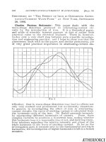
Curve
1
is
for
25
cycles
and
a
maximum
flux-density
of
6,850
lines
of
induction
per
square
centimeter.
Curve
2
is
for
25
cycles
and
amaximum
flux-density
of
11,300
Curve
3
is
for
25
cycles
and
a
maximum
flux-density
of
12,800.
A
sine-wave
of
pressure
at
the
terminals
of
the
magnetizing
coil
would
have
given
flux-densities
of
7,000,
12,000
and
15,-
000
lines
respectivelv.
The
following
table
gives
for
another
sample
the
flux-densities
calculated
on
the
basis
of
a
sine
wave
electromotive
force
and
the
true
flux-densities
determined
from
the
average
values
of
the
electromotive
force
wave:
B
True
B
Ratio
of
True
B
to
Casldc-
Calculated
on
basis
lated
B.
of
sine
wave.
60
Cycles.
25
Cycles.
60
Cycles.
25
Cycles.
4,000
4,000
4,000
1.00
1.00
7,000
6,800
6,500
0.97
0.93
10,000
9,400
9,100
0.94
0.91
12,000
11,000
10,600
0.92
0.88
15,000
12,200
0.81
17,500
13,200
0.76
20,000
14,100
0.71
A.
Henry
Pikler
(by
letter):
Professor
Bedell's
paper
gives
the
impression
that
the
hysteresis
loop
is
the
only
cause
of
the
dis-
tortion
of
alternating-current
wave-forms.
This
is
not
so.
The
ÆTHERFORCE
1906]
DISCUSSION
AT
PITTSBURG.
711
distortion
is
primarily
due
to
the
change
in
permeability
during
onie
cycle
of
magnetism;
the
hysteresis
is
only
accidental.
Mr.
Steinmetz
indicates
how
the
induced
electromotive
force
wave
form
will
become
distorted
in
a
transformer
by
magnetizinlg
it
with
a
sine
wave
current.
To
sustain
this
contention,
I
refer
to
my
oscillograms
taken
in
June,
1903,*
There
it
is
shown
that
a
constant
transformer
terminal
voltage
can
be
maintained
by
various
forms
of
magnetizing-current
waves
which,
as
they
become
more
and
more
sinusoidal
will
make
the
transformer
electromnotive
force
wave
take
the
shape
of
the
previously
dis-
torted-curront
wave.
*Electrwal
World
and
Engineer,
1903,
Vol.
XLII,
No.
6,
p,
213.
ÆTHERFORCE