a mcleish underwater concreting and repair 1994 isbn 0470234032
Bạn đang xem bản rút gọn của tài liệu. Xem và tải ngay bản đầy đủ của tài liệu tại đây (6.99 MB, 155 trang )
UNDERWATER
CONCRETING
AND
REPAIR
Edited
by
Andrew McLeish
Head
of
Structural
Appraisal,
W S
Atkins
Structural Engineer-
ing,
Epsom,
Surrey,
UK
Editorial
Advisor
Tony
C
Liu,
US
Army
Corps
of
Engineers,
Washington
DC
20314,
USA
Halsted
Press
An
imprint
of
John Wiley
&
Sons,
Inc.
New
York
Toronto
©
1994 Andrew McLeish
First published
in
Great Britain 1994
Library
of
Congress
Cataloging-in-Publication
Data
Available upon request
ISBN
O 470
23403
2
All
rights reserved.
No
part
of
this publication
may be
reproduced
or
transmitted
in any
form
or by any
means, electronically
or
mechanically,
including photocopying, recording
or any
information
storage
or
retrieval system, without either prior permission
in
writing
from
the
publisher
or a
licence permitting restricted copying.
Printed
and
bound
in
Great Britain.
Preface
The
construction
of a
wide range
of
structures including bridge piers,
harbours,
sea and
river defences over
many
decades,
and
more recently
the
development
of
offshore
oil fields, has
required placement
of
concrete
underwater.
This process
can be
successfully
carried
out and
sound, good
quality
concrete produced
if
sufficient
attention
is
paid
to the
concrete
mix
itself
and the
methods
of
construction employed.
This book
is
intended
for the
practising engineer,
who
whilst
being
experienced
in the
techniques
and
approaches
for
construction above
water
needs practical advice
and
guidance
on
underwater concreting.
The
contents
of the
book
are
arranged
in a
progressive order starting
with
considerations that must
be
given
to the
design
of the
concrete
mix to
minimise
the
effects
of
contact
with
water,
and to
take into account
the
practicalities
of
placing
and
compacting
the
concrete.
The
methods that
can
be
employed
to
prepare
the
construction site, types
of
form
work
available
and
methods
of
placement
are
then described
and
their relative
merits
and
potential
problems discussed.
As
much underwater
concrete
is
of
considerable
age and is
exposed
to
severe conditions, techniques
for
inspecting
underwater
to
identify
defects,
and the
methods
of
repair that
can
be
employed
are
important issues that
are
described. Finally,
the
durability
of
concrete
in an
underwater environment
is
discussed
and the
potential areas
of
concern
highlighted.
A
McLeish
January
1994
List
of
Contributors
R S
Mangat
Head
of
Research,
School
of
Construction,
Sheffield
Hallam University,
City
Campus, Pond
Street,
Sheffield,
UK.
A
McLeish
Head
of
Structural Appraisal,
W S
Atkins Structural Engineering,
Woodcote
Grove,
Ashley
Road,
Epsom,
Surrey,
UK.
FRendell
Anglia
Water Services
Ltd,
Compass
House,
Chivers Way, Histon,
Cambridge,
UK.
P J
Scatchard
Samos
Ltd,
3
West Drive, Brighton,
UK.
BWStaynes
Consultant
Engineer,
6
Shenstone,
Lindfield,
West Sussex,
UK.
Editorial
Advisor
TCLiu
US
Army
Corps
of
Engineers, Washington
DC
20314,
USA
vii
This page has been reformatted by Knovel to provide easier navigation.
Contents
Preface v
List of Contributors ix
1. Mix Design for Underwater Concreting 1
1.1 Introduction 1
1.2 Characteristic/Target Strength Relationships 2
1.3 Strength/Age Requirements 5
1.4 Materials 5
1.5 Properties Required of Underwater Concrete 11
1.6 Test Methods 14
References 19
2. Excavation and Preparation, Design and
Installation of Formwork 21
2.1 Introduction 21
2.2 Excavation and Preparation of Foundation 22
2.3 Tolerances and Setting Out 23
2.4 Selection of Type of Form Work 25
2.5 Design Loadings 27
2.6 Selection of Type of Form Work 29
References 31
3. Underwater Inspection 33
3.1 Introduction 33
3.2 The Behaviour of Concrete in Submerged
Structures 36
viii Contents
This page has been reformatted by Knovel to provide easier navigation.
3.3 Inspection 43
3.4 Inspection Techniques 46
3.5 The Inspection and Reporting Process 54
References 59
4. Methods of Placing Concrete Underwater 63
4.1 Introduction 63
4.2 Selection of Method 65
4.3 Control and Monitoring 82
References 83
5. Underwater Repair of Concrete 85
5.1 Introduction 85
5.2 Access to the Repair Site 86
5.3 Preparation of the Concrete and Reinforcement 89
5.4 Repair Materials 94
5.5 Repair Techniques for Concrete 102
5.6 Reinforcement Repairs 110
References 114
6. Durability of Concrete Underwater 115
6.1 Introduction 115
6.2 Marine Environment 116
6.3 Chemical Attack 119
6.4 Prevention of Chemical Attack 123
6.5 Resistance to Penetration of Deleterious
Substances 129
6.6 Corrosion 137
6.7 Physical Deterioration 138
References 142
Index 147
I
Mix
design
for
underwater
concrete
B W
Staynes
1.1
Introduction
Concrete
mix
design involves
the
selection
and
proportioning
of
available
materials
to
produce concretes which
in
both
the
fresh
and
hardened state
meet
the
requirements
of a
specified application. Generally these require-
ments
concentrate
on the
properties
of
workability/flow,
compressive
strength
and
durability.
The
overall concreting operation needs
to be
achieved as
economically
as
possible
and for
simple concrete construction
this
often
requires
the mix
design
to
minimize material costs, i.e.
the
cost
of
the
ingredients. However,
for
some specialized applications higher
concrete material costs
are
more than compensated
for by the
savings
achieved
at the
transportation/casting
stage,
or the
speed
with
which
the
structure
can
start
to
earn
revenue.
In
the
case
of
underwater concreting operations,
mix
design plays
a
significant
part
in the
overall
efficiency
of
construction
in
terms
of
technological
quality
and
overall economics. Almost without exception
trial
mixes
will
be
required.
The
properties needed
for
underwater concrete
are
directly related
to
the
method
of
placement,
and
this technology
is
covered
in
Chapter
4. The
principal
methods include:
•
tremie (including
the
'hydrovalve')
•
pumping
with
free
fall
•
skip (bottom opening)
•
prepacked (preplaced) aggregate concrete
•
prepackaged—above
water
—under
water.
In
addition,
the
geometry
of the finished top
surface (horizontal
or
laid
to
falls)
needs
to be
taken into account
as
most concrete placed underwater
has
a
tendency
to flow to a
level
surface.
Parameters relevant
to
each type
of
placing condition
are
indicated
in
Table 1.1.
Table
1.1
Relevant parameters
Parameter
Strength
Durability
Segregation/washout
Resistance during:
internal
flow
free
fall
quiescent
free
fall
turbulent
Placing
method
Tremie
i
y
Pumping
with
free
fall
;
!
Skip
i
i
Prepacked
(preplaced)
aggregate
concrete
4
Prepackaged
Above
water
i
Under
water
i
The
parameters involved
in
normal concrete
mix
design
and
their
interaction
are
given
in
Figure
1.1
with
the
additional underwater concrete
factor
'washout'
and its
interactions shown
in
bold.
The
placing conditions
for
a
particular application have
a
significant
influence
on the
degree
of
washout
resistance required. Thus
the mix
design process needs
to
take
account
of
this,
particularly with regard
to
aggregate
selection,
cement
content
and the use of
admixtures.
Unless practical test data relating
to the
specific
combination
of
aggre-
gates,
cements, admixtures
and any
other
constituents
are
available,
the
use of
trial
mix
procedures
will
form
an
essential part
of the mix
design
process.
These
are
likely
to
take
the
form
of
initial laboratory trials (which
may
include washout
resistance
testing) followed
by
full-scale
trial mixes.
In
the
latter case, where
new or
unusual placing conditions
are to be
encountered,
effective
performance
in
sample pours should also
be
assessed.
1.2
Characteristic/target strength relationships
Variation
in the
compressive strength
of
concrete specimens
are
usually
assumed
to
conform
to a
'normal'
distribution
as
illustrated
in
Figure 1.2.
For
general concreting
operations
variability
of
quality control test results
is
caused
by
variations
in the
materials used, production operations
and
sampling/testing
techniques.
Fig.
1.1
Concrete
mix
design. Parameters
and
interactions
The
form
of a
normal distribution curve
can be
denned
entirely
by its
mean
(ra)
and its
standard deviation
(S),
where
&(x-m)
2
A
~V
n-\
and
n is the
number
of
test
results.
The
area
under
the
normal distribution curve shown
in
Figure
1.2
represents
all the
available
test
results.
The
characteristic strength (spe-
Frequency
Compressive
strength
(MN/m
2
)
Fig.
1.2
Normal
distribution
of
concrete strengths
Strength/age
requirement
Size
of
pour
and
chemical
attack
Temperature
Method
of
compaction
Placing
conditions
Characteristic
strength
Quality
and
type
of
cement
Admixtures
Workability
WASH-OUT
RESISTANCE
Mean
strength
W/C
W/A
Aggregate,
properties,
size
shape, texture
grading
Quality
control
Cement
content
Water
content
Aggregate
content
Mix
proportions
Batch
weights
cified
strength)
is
usually
identified
by the
design engineer
and is
included
in
the
specification (e.g.
30MN/m
2
at age
28
days
under standard curing
conditions).
As it is
statistically impractical
to
establish
a
distribution curve
for
which
zero results
are
defective,
i.e.
less than
the
characteristic/specified strength
(ore),
it is
common practice
to
determine
the
mean/target
strength (re-
quired average strength) (am)
for
concrete
mix
design purposes
on the
basis
of an
allowed percentage
of
defective test results
(X),
i.e.
am = ac
-I-
kS
where
X(%)
k
5
1.64
2.5
1.96
1
2.33
In
practice,
S is
based
on
experience
or is
assumed
to be
4-8
MN/m
2
(Ref.
1).
Typically
X
=5%.
Ideally
5
should
be
calculated
from
results taken
from
the
production
operation used
on the
project
in
question.
If
these data
are not
available,
values
can be
assumed such
as the
4-8
MN/m
2
values recommended
by the
DOE
1
or by
ACI.
2
Thus
the
mean
or
target strength
for a mix
with
a
characteristic strength
of 30
MN/m
2
,
a
standard deviation
of 6
MN/m
2
and
allowing
for
5%
defectives
is
am
= ac + kS
=
30+1.64x6
=
39.8
MN/m
2
,
i.e.
40
MN/m
2
Depending
on how
critical
failure
of
particular components
may be,
concrete specifications
often
include safeguards additional
to the
limitation
on the
percentage defective test results which
fall
below
the
specified
characteristic strength. Examples
of
additional safeguards
include:
• the
average strength
of any
three consecutive test specimens must
exceed
the
characteristic strength
by a
given
amount,
say 7.5
MN/m
2
• no
individual test result
may
fall
below
a
specified
proportion
of the
characteristic strength, e.g.
85%.
While
the
above
are
details
associated
with
specifications,
they
can
have
a
significant
influence
on the
approach
to the
selection
of the
mean/target
strength
used
for
concrete
mix
designs.
The
quality
of
concrete
in the finished
structure
may
additionally
be
affected
by
variations
due to
transportation, placing, compaction
and
curing
operations.
As
these operations
can be
witnessed
in
most
'dry'
placing
condition applications, good supervision
can
ensure that
the
quality
of
concrete
in
structural components
has a
known relationship
to the
characteristic strength based
on
quality control specimens.
Detailed observation
of
transportation, placing, compaction
and
curing
is
much more
difficult
to
achieve
for
concrete placed underwater. Thus,
while
underwater concrete test specimens cast
in the dry can be
expected
to
follow
a
typical normal distribution, much greater variability
can be
expected
in an
underwater structure. Allowance
can be
made
for
such
variations
by
increasing
the
standard deviation
and
thus
the
margin
between characteristic strength
and
target strength.
The
extent
of the
increase
is
difficult
to
estimate
and
needs
to
take account
of
detail placing
techniques,
the
resistance
of the
specific
concrete
to
washout/segregation
and
flow/self-compaction
qualities
in
relation
to
placing conditions.
It
follows
that
it is
better
to
increase
the
partial
safety
factor
for
materials
at
the
structural design stage. This enables engineering judgment
to be
exercised
in
determining
the
overall
safety
factor which
will
also include
allowance
for the
uncertainties
in
applied loading.
These
could
be
con-
siderable
in
some underwater concrete applications.
1.3
Strength/age requirements
Specific
location conditions dictate
the
characteristic strength requirements
for
each application
condition.
Thus specified grades
of
concrete vary
from
25MN/m
2
for
cofferdam plugs
to
65MN/m
2
in the
splash zone
of oil
production
platforms.
In the
above examples
the
rate
of
gain
of
strength
is
relatively
unimportant
as
compressive strength
is
unlikely
to be a
critical
performance
parameter
for
cofferdam
plugs
and,
in the
case
of oil
rigs,
a
considerable time
will
elapse between casting
and the
concrete being
subjected
to
service
conditions.
Thus
the
characteristic strengths
are
likely
to be
defined
at an age of 28
days
for
simplicity
and
clarity
of
specification.
At one
extreme,
for
concrete placed
in
situ
in the
tidal range, perhaps
with
limited protection, early
age
strength
will
be a
critical factor. Under
such
conditions significant strength
may
need
to be
developed within
a few
hours. Such
difficulties
may
dictate
the use of
precast sections and/or
the
use of
packaging techniques.
On
the
other
hand,
owing,
for
example,
to
tidal conditions, concrete cast
underwater
has to be
placed
in
lifts.
To
ensure
a
good bond/homogeneity
between successive placements, slow early
age
strength development
can
be
particularly advantageous. Such requirements need
to be
built into
the
specification
and
taken into consideration
in the mix
design.
1.4
Materials
1.4.1 Aggregates
As it is
usually impossible
to
achieve detailed visual inspection during
the
placing
of
underwater
concrete,
and it is
usually necessary
for the
concrete
to flow and
self-compact,
it is
important
to
select aggregates
and
gradings
which
are
particularly resistant
to
segregation
and
bleeding
and
which
have
high
cohesion.
1.4.1.1
Coarse aggregates
It is
well known that rounded aggregates achieve more dense packing
and
have
reduced water demand
for a
given degree
of
workability than
do
crushed rock aggregates. Thus
the use of
rounded aggregates generally
tends
to
increase cohesion
for a
given sand
friction
and
cement content
and
to
have
a
reduced tendency
to
segregation
and
bleeding.
However, strength
and
abrasion resistance
are
particularly
significant
parameters
in
some underwater applications
and it may
thus
be
necessary
for
these reasons
to
select crushed rock aggregates. When this
is the
case
particular care must
be
paid
to the
overall grading
of the
aggregate.
1.4.1.2 Fine aggregates (sand) (less than
5 mm)
The
only special requirement
for the
sand
fraction
over
and
above those
needed
for
normal concreting mixes
is
that there should
be a
significant
proportion
with
a
particle size less than
300
jxm.
At
least
15-20%
of the
sand
fraction
should pass
a 300
(xm
sieve
as
this
is
necessary
to
enhance
the
cohesive properties
of
concrete
to be
placed under water. When suitable
sands
are
unavailable
it is
necessary
to
increase
significantly
the
cement
content
of
mixes,
or add
pulverized
fuel
ash or
ground granulated blast
furnace
slag.
1.4.1.3 Grading
As
underwater concrete needs good
flow and
self-compacting
properties,
and
sufficient
cohesion
to
resist segregation
and
bleeding,
the
aggregate
grading
requirements
are
very similar
to
those
needed
for
concrete pump
mixes.
3
Pump
mix
requirements include
the
above properties plus
the
need
for
the
cement
paste
and/or mortar
phase
to
form
a
lubricating
film on the
pipe walls. While this latter requirement
is not
essential
for
underwater
concrete mixes,
it is
common practice
to
have relatively high cement
contents
to
improve cohesion, compensate
for
segregation
effects
and
allow
for the
inevitable
losses
of
cement
due to
'washout'.
Continuous grading curves have been
found
to
give
the
best results.
Generally
20 mm
maximum size aggregate
is
most satisfactory
with
a
sand
content
of at
least
40% of the
total aggregate.
The
well known
Road
Note
4
4
grading curves shown
in
Figure
1.3
provide
a
useful
guide. Grading
curve
numberS
is a
suitable initial target
for
trial mixes. However, this
needs
to be
adjusted
so
that
the
percentage passing
the 300
JJLHI
sieve
is
increased
from
5% to
about
8%.
At no
stage should
the
grading
be
coarser
than
grading curve number
2.
To
achieve cohesive mixes,
the
relative proportions
of
coarse
aggregate
Nominal sieve aperture sizes
Grading curves
for
20mm
max
size aggregate
Fig.
1.3
Grading
curves
for
aggregates
and
sand need
to be
adjusted
to
minimize
the
total voids
in the
mix. This
will
depend
on the
shape
of the
various particles.
If
necessary
a
'void
meter'
can be
used
to
optimize
the
proportions. This approach
is
recom-
mended
if
crushed rock aggregates
are
used.
1.4.2
Cements
Sulphates
in
ground water
and
particularly
in sea
water present
the
well
known
problem
of
tricalcium aluminate
(C
3
A)
reaction, causing swelling
and
the
related disintegration
of
concrete.
As
underwater concretes
usually
have
comparatively large cement contents (over
325
kg/m
3
),
attack
due to
sulphates
in
ground water
can be
counteracted
in the
usual
way by
adjusting
the
cement content and/or
the use of
sulphate-resisting Portland
cement.
The
presence
of
chlorides
in sea
water
can
reduce
the
above
effect
of
expansion
and
deterioration
of
concrete.
The
gypsum
and
calcium
sul-
phoaluminate resulting
from
sulphate attack
are
more soluble
in
chloride
solutions
and are
leached
out of
concrete
permanently immersed
in sea
water. However,
concrete
in the
splash zone
and
above
is
particularly
vulnerable
as not
only
does
sulphate attack occur,
but
also pressure
is
exerted
by
salt crystals formed
in the
pores
of the
concrete
at
locations
where
evaporation
can
take place. Chlorides migrate above normally
wetted
areas owing
to
capillary
action,
and the
production
of
concrete
with
low
permeability reduces this
effect.
Fundamental
to the
durability
of
concrete
subjected
to
attack
due to
sulphates
in
ground water
and sea
water
is
minimizing
the
porosity
of the
concrete
at
both
the
engineering level
by
achieving
full
compaction,
and at
the
micro level
by
minimizing
the gel
pores.
The
latter
can be
considerably
reduced
by
using
low
water/cement
ratios.
ACI
committee
201.2R
recom-
Percentage passing
mends that water/cement ratios should
not
exceed 0.45
in
conditions
of
severe
and
very severe exposure
to
sulphates i.e.
SO
3
content
of
water
exceeding
1250
ppm
and
8300
ppm
respectively.
5
However, this needs
to
be
accompanied
by the use of
high cement contents, plasticizers
or
superplasticizers
if a
high level
of
self-compaction
is to be
achieved.
The
use of
cement replacement materials such
as
pulverized
fuel
ash
and/or
the
addition
of
condensed micro silica (silica
fume)
can
considerably reduce
the
porosity
of
concrete
and
thus
its
susceptibility
to
sulphate attack
and
chloride crystallization.
1.4.2.1
Ordinary Portland cement (OPC)
OPC or
ASTM Type
I
having
not
more than
10%
C
3
A
is
suitable
for
underwater
concrete construction where
the
sulphate content (expressed
as
concentration
of
SO
3
)
of
ground water does
not
exceed 1200 parts
per
million
(ppm),
and for
marine structures which
are
permanently sub-
merged.
1.4.2.2 Sulphate-resisting Portland cement
(SRPC)
SRPC
(ASTM
Type
V or
Type
II
with
a 5%
limit
on
C
3
A))
with
its
reduced tricalcium aluminate content should
be
used where
the
SO
3
content
of
ground water exceeds 1200 ppm.
Its use in
marine structures
in
the
splash zone
and
above
is
less straightforward. While
a low
C
3
A
content
provides protection against sulphates,
it
reduces protection
to
steel rein-
forcement
in
chloride rich
environments.
6
The
C
3
A
content should
not be
less
than
4% to
reduce
the
risk
of
reinforcement corrosion
due to
chlorides.
7
1.4.2.3 Low-heat Portland cement (LHPC)
Large pours
of
concrete cast underwater
are
particularly susceptible
to
thermal cracking
as
relatively high cement content concretes
are
used.
LHPC
(ASTM Type
II or
Type
IV) not
only reduces
the
rate
of
heat
evolution
but
also provides protection against sulphate attack owing
to the
low
levels
of
tricalcium aluminate
in
this cement.
The use of
cement
replacement materials
is an
alternative method
of
reducing thermal
effects
and
provides additional
benefits.
1.4.3
Anti-washout
admixtures
Anti-washout
admixtures
can be
used
to
reduce
the
risk
of
segregation
and
washout
with
the
tremie methods
of
placement, improve self-compaction/
flow
properties
and
enable methods
of
placement which
are
faster
and
less
sensitive
to
operational
difficulties
to be
used.
In
particular, combinations
of
admixtures have been developed
to
produce
a
'non-dispersible
concrete'
(NDC) which
can
free
fall
through
a
depth
of
about
1 m of
water without
significant
washout
of the
cement
phase.
1.4.3.1
Cohesion improvement
Materials
that have been tried with
varying
degrees
of
success
to
produce
non-dispersible
concrete
include:
8
'
9
•
natural polymers (gum arabic,
methy
!cellulose,
hydroxyethy
!cellulose,
carboxymethylcellulose)
•
synthetic polymers
(poly
aery
lonitrile,
poly
aery
!amides,
polymethacry-
Hc
acid,
polyacrylates,
copolymer
of
vinyl
acetate,
maleic acid anhyd-
ride)
•
inorganic powders (silica
gel,
bentonite, micro silica)
•
surface-active agents (air entraining with
and
without
set
retarder,
plasticizers).
It is
essential that
the
selected materials
are
compatible with cement
hydrates. Several
of the
above cause severe retardation
of the
hydration
process
and
limit
the use of
superplasticizers.
The
ionic polymers
are
insoluble
in
water containing hydration products owing
to the
presence
of
calcium
ions
and
thus
fail
to
increase
its
viscosity.
Table
1.2
gives details
of the
properties/influences
of
some
of the
more
commonly
used admixtures
to
improve cohesion
in
underwater
concrete.
Table
1.2
Properties
and
influences
of
admixtures
Admixture
Micro
silica
0.1-0.2
juim
microspheres
typically
over
90%
reactive silica
Non-ionic
cellulose ether
Derivative,
up to 500
cellulose
ether
units;
formula,
see
Figure
1.4;
n up to
500; equivalent
molecular
length
0.5
jxm
Non-ionic poly
aery
lamide
Typical molecular mass
5 x
10
6
,
approximately
70000
units;
formula,
see
Figure
1.5;
equivalent
molecular length
10
juim
Property/influence
Compatible
with
cement
Increase
compressive
and
tensile strength
Increased rate
of
gain
of
strength
Reduce porosity
Increase durability
Increases resistance
to
abrasion-erosion
effects
Increase cohesion
Compatible with cement
Retards hydration reaction
Large increase
in
viscosity
Large
increase
in
cohesion
Very
good segregation resistance
Self-levelling/-compacting
Compatible with cement
Retards
hydration reaction
Large increase
in
viscosity
Large increase
in
cohesion
Excellent
segregation resistance
Flow
resistance (20% surface gradient)
Fig.
1.4
Cellulose ether
unit
1.4.3.2
Flow
improvement
High
slump concretes generally
flow
underwater
and the
addition
of
superplasticizers
to
enhance this property alone
is not
usually
required.
However, proprietary underwater concrete admixtures
are a
blend
of
several compounds
and
usually contain
a
superplasticizer
to
improve
the
flowing
properties
of
what would otherwise
be a
very sticky
concrete.
The
superplasticizers most commonly used
in the
construction industry
are
based
on
melamine formaldehyde
and
naphthalene formaldehyde. While
the
former
are
compatible with
the
soluble polymers used
to
increase
cohesion, naphthalene formaldehyde-based superplasticizers have
been
found
to be
ineffective
when used with cellulose ether.
1.4.3.3 Cement replacement
with
PFA or
GGFS
Partial cement replacement with pozzolanic materials such
as
pulverized
fuel
ash
(PFA)
or
ground
granulated
blast
furnace slag
(GGFS)
not
only
Fig.
1.5
Polyacrylamide
unit
reduces
the
risk
of
thermal cracking
in
large pours,
but
also improves
the
performance
of
micro silica
and
cellulose ether
at
producing concretes
capable
of
resisting washout
of the
cement
and fine
phases
of
concrete.
Typical commercial underwater concrete admixtures reduce washout
from
20-25%
down
to
about
10%.
However, when Portland cement
is
used with
30% PFA or 50%
GGFS
replacement, washout
is
reduced still
further
for
the
same admixture
dose.
The
most cost-effective method
of
producing
NDC is
likely
to
involve
the use of
partial cement replacement
with
PFA or
GGFS
in
conjunction with
NDC
admixtures.
1.5
Properties
required
of
underwater
concrete
1.5.1
General
The
properties
required
for
concrete
placed under water
by
tremie, pump
with
free
fall
and
skips are:
•
specified strength
and
durability
•
self-compaction
(i.e.
displace accidentally entrained air,
and
flow
to fill
formwork)
•
self-levelling
or flow
resistance (depending
on
placing conditions)
•
cohesive
(i.e.
segregation resistance)
•
washout resistance (the degree depending
on the
method
of
place-
ment).
The
extent
of the
interelationship between
the
above
properties
depends
on
the mix
design approach used
to
achieve them.
As
discussed
in
Section 1.2,
the
specified strength
is
normally based
on
test samples cast
in
dry
conditions.
Its
relationship
to the
characteristic strength used
at the
design
stage
is
chosen
to
take into consideration reductions
to be
expected
when
concrete
is
placed under water.
1.5.2
Concrete without admixtures
Well
executed tremie/hydrovalve techniques have been
found
to
produce
underwater
cast concrete with
up to 90% of the
strength
of the
same
concrete cast
in dry
conditions. However,
if
proper
control
of the
base
of
the
tremie pipe
is not
achieved and/or
the
concrete
is
required
to flow
over
significant
distances owing
to
lack
of
mobility
of the
placing locations,
strengths
as low as 20% of the
equivalent concrete cast
in air can
occur.
This loss
of
strength
can be
attributed
to
segregation/stratification
and/or
washout
of the
cement phase
of the
concrete.
10
It
should
be
noted that
if
the
whole
of a
vertically drilled
core
is
analysed
for
cement content there
Percentage
of
full
compaction
Fig.
1.6 The
influence
of
compaction
on the
strength
of
concrete
may
be
little apparent loss
of
cement. More careful examination
may
reveal
that
a
considerable proportion
of the
cement
is in the
upper layers
of
the
concrete, possibly appearing
as a
thick laitance
on the top
surface.
Parts
of the
concrete
are
likely
to
have lost over
25% of
their original
cement content.
The
significance
of a
lack
of
full
compaction
on
concrete strength
is
well
known
(Figure
1.6).
As it is
impractical
to
compact concrete placed
underwater
by
physical means using vibrators
or by
tamping,
it is
essential
that
the
concrete should have
sufficient
workability
to
displace
any
accidentally
entrained
air
during
the
settlement/flow period
after
the
concrete
has
been
placed.
Established practice
is to
specify
slump values
of
120-200
mm.
These
values
offer
a
useful
guide
for
trial mixes but,
as
concretes with
a
given
slump
can
have varying
flow
properties,
the
ability
to
self-compact needs
to
be
assessed
by
practical trials.
In
order
to
reduce porosity
and
achieve strength requirements
at
high
water
contents
and
compensate
for
segregation/losses,
it is
necessary
to
have relatively high cement contents. Traditional
mix
designs have cement
contents
of
325-450
kg/m
3
. Experience
has
shown that concrete with
relatively
low
cement content
has
better abrasion resistance. Where this
performance
criterion
is
important and/or where large pours
can
give rise
to
thermal cracking problems,
it is
preferable
to use the
lower
end of the
above range. However,
the
cohesion needed
to
avoid segregation
and
washout
requires
a
minimum
fines
content resulting
in the
need
for
cement
contents
as
high
as 400
kg/m
3
.
These
conflicting
performance requirements
have
led to the use of
admixtures
and
cement replacement materials.
1.5.3
Non-dispersible
concrete
The
inherently slow nature
of
tremie placement coupled with
its
operation-
al
difficulties,
quality uncertainties
and
wastage have
led to the
develop-
ment
of
non-dispersible
concretes. Non-dispersible concretes
can be
produced with varying degrees
of
cohesion
and
washout
resistance.
On the
one
hand
it is
possible
to
design
a mix
which reduces
the
quality
Percentage
of
strength
at
full compaction
uncertainties
of
tremie placed concrete resulting
from
uncontrolled inter-
nal
flow
velocities
and
changes
in the
geometry
of the
concrete/water
interface.
The
relatively modest increases
in
cohesive properties required
can
be
achieved
by the
addition
of 10%
micro silica
(by
weight
of
cement)
to a
traditional
mix
containing about
325 kg of
cement
per
cubic metre
of
concrete.
11
Depending
on
strength
and flow
requirements,
a
superplasticiz-
er can
also
be
included.
Fully
non-dispersible
concretes,
on the
other hand,
can be
discharged
from
a
pump delivery pipe through
1
m
or so of
water without
significant
loss
of
cement.
The
highly
cohesive properties required
are
achieved
by the
addition
of
2-3%
of
cellulose ether
or
polyacrylamide.
They
are
often
blended
with
a
melamine formaldehyde superplasticizer,
and in
some cases
micro silica,
to
produce
the
commercially available underwater concrete
admixtures.
As
extensive testing
is
necessary
to
ensure
the
compatibility
of
the
combined ingredients,
it is
advisable
to use
commercial products rather
than combine
the
basic materials on-site. Nevertheless,
it is
essential
to
prepare trial mixes
from
the
combination
of
aggregates, cement
and
admixtures
used
on a
specific
project
to
ensure that
the
required perform-
ance
is
achieved. Some proprietary non-dispersible admixtures
and
non-
dispersible prebagged concretes
are
listed
in
Tables
5.1
and
5.2, respec-
tively.
Figure
1.7
enables
a
comparison
to be
made between
the
strengths
of a
control
mix and a
non-dispersible concrete cast
in air and in
water.
Figure
1.8
illustrates
the
loss
of
cement
and fines
during
free
fall
through
water
at
various
doses
of
admixture.
The
increase
in-speed
of
placement, reliability
of
concrete
quality
and
savings
in
preparation
and
concrete
wastage
justify
the use of
non-
dispersible concretes despite their substantially higher unit material cost.
Unmodified/in
air
1 %
Polyacrylamide/in
air
1 %
Polyacrylamide/in water
Unmodified
in
water
Proportional strength
(%
28 day
zero polymer
in
air)
Age
at
test
(days)
Fig.
1.7
Comparison between control
mix and 1%
polyacrylamide-modified
concrete
Microsilica/polymer
addition
(%
of
cement)
Fig.
1.8
Weight
loss
under
tree
fall
1.6
Test methods
1.6.1
General
It is
important
to be
able
to
evaluate
the
effects
of
non-dispersible
concrete
admixtures
not
only
in
terms
of
obvious short-term parameters
but
also
their
influence
in the
longer term
and
over
the
full
life
of the
structure.
Tests
are
required
to
evaluate segregation
resistance,
workability/flow,
chemical
compatibility, influence
of
admixtures
on
strength
and
effective-
ness
at
full-scale.
1.6.2
Washout tests
Resistance
to
washout
of the
cement phase
is
fundamental
to the
produc-
tion
of a
concrete
which
can
free
fall
through
1
m
or so of
water without
serious degradation.
1.6.2.1
Transmittance test
In
this case
a
measured slug
of
concrete (typically
0.5
kg) is
dropped into
a
vessel containing about
51
of
water.
The
turbidity
of the
water
is
measured
using
standard light
transmittance
apparatus.
By
calibration using standard
known
dispersions
of
cement
in
water,
the
amount
of
washout occurring
as
a
result
of the
concrete
falling
through
the
water
can be
determined
(Figure
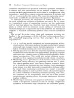
1.9).
12
A
variant
of
this test
is to
agitate
the
water with
a
laboratory stirrer
for a
(Micro silica)
(Polymer)
Micro Silica
Polyacrylamide
Cellulose Ether
Weight loss
(%
of
initial weight)
Cement concentration
(%
by
weight)
Fig.
1.9
Relationship
between cement
concentration
and
transmittance.
Ordinary
Portland
cement
was
dispersed
in
water
prescribed period. This
is a
more stringent test
but
produces similar
comparative results.
1.6.2.2 Stream test
This
is a
straightforward test
in
which
a
sample
of
concrete
is
placed
in a
2 m
long channel
set at an
angle
of
20°.
A
measured volume
of
water
is
poured down
the
channel
and
depending
on the
segregation resistance
of
the
concrete, cement
is
washed
out.
13
The
degree
of
washout
can be
judged
on a
comparative basis
by
visual observation
and on
this basis
is
subjective.
However,
by
standardizing
the
volume
and
speed
of
water
flow, and
collecting
it at the
downstream
end of the
channel,
the
transmittance
of the
effluent
can be
measured
as
above, thus enabling comparative perform-
ance
to be
judged
on a
numerical basis.
1.6.2.3 Plunge test
In
this case
a
sample
of
concrete
is
placed
in an
expanded metal
or
wire-mesh
basket
and
allowed
to
fall
though
1.5 m of
water
in a
vertically
mounted
tube.
The
sample
is
hauled
to the
surface
slowly
(0.5m/s),
weighed
and
then
the
process
is
repeated.
A
total
of five
drops
has
been
accepted
as
standard.
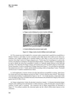
11
A
typical relationship between
the
number
of
drops
and
percentage weight loss
is
shown
in
Figure
1.10.
While
the
rate
of
fall
of the
basket
and
concrete
is
relatively faster than
the
free-fall
speed
of
concrete alone,
the
protective
effect
of the
mesh
of the
basket mitigates
against
this.
The
results
of the
test
are
repeatable,
enabling good compari-
sons between
different
concretes
to be
made.
It is
generally thought
to
relate well
to
practical conditions
of
free
fall
from
a
pump delivery hose
through
1-2 m of
water.
A
similar test method
(CRD-C61-89A)
has
been
used
by the US
Army Corps
of
Engineers.
14
A
variation
of
this test
has
been used
to
assess
the
relative performance
Transmittance
(%)
Number
of
immersions
Fig.
1.10
Plunge test result
of
admixtures
at a
range
of
velocities
of the
sample
of
concrete.
The
results
are
shown
in
Figure
1.11.
1.6.2.4
Segregation test
A
segregation susceptibility test, originally introduced
by
Hughes,
15
and
subsequently
revised
by
Khayat,
16
may be
used
to
evaluate
the
separation
of
coarse aggregate
from
fresh
concrete when placed under water.
The
test
describes
the
scattering
of
concrete
after
having been dropped over
a
cone
Control
1 %
Polymer
1 %
Polymer
+ 30% PFA
replacement
1
%
Polymer
+ 20%
Micro Silica
Weight
loss
(%)
Unmodified Concrete
10%
micro
silica
1 %
Polyacrylamide
1%
Cellulose Ether
Plunge
test
velocity
(m/s)
Fig.
1.11
Influence
of
plunge test velocity
on
weight loss
Free
fall
velocity
Weight
loss
(% of
initial weight)
from
two
hoppers,
once
in air and
another time through water.
The
upper
hopper
is filled
loosely with
concrete,
then
a
trap door
is
opened allowing
the
concrete
to
drop into
the
lower
hopper.
The
concrete
is
then allowed
to
fall
over
a
smooth steel
cone,
in air or
through water,
and
scatter
on to two
concentric wooden discs.
The
weights
of
fresh
concrete
and
sieved
and
oven-dried coarse aggregates which were collected
from
the two
discs
are
used
to
determine
the
separation index (SI).
1.6.3
Workability/flow
Workability
and flow
properties
are
very important
for
concretes used
under
water,
as
tamping
and
vibration
to
achieve compaction
are
imprac-
tical,
and the
full
extent
of the
form
work
needs
to be filled
from
a
relatively
few
specific
pour locations.
The
standard slump
and flow
tests
(BS
1881:
Parts
102 and
105)
are
appropriate
but it is
interesting
to
note that where
cellulose ether
has
been used
to
produce
non-dispersible
concrete
the
slump
value gradually increases with time
(up to 2 min
after
removal
of the
conical
mould),
and the
diameter
of the
concrete continues
to
increase
following
the flow
table test.
It is
common practice
to
allow
sufficient
time
for
the
concrete shape
to
stabilize prior
to
taking
a
reading. Figure
1.12
illustrates
the way in
which slumps changes
with
time
for a
high slump
concrete.
The US
Army Corps
of
Engineers' standard test method, CRD-C32-84,
can
also
be
used
for
determining
the flow of
concrete intended
to be
placed
underwater
using
a
tremie.
14
The
value
'slump
flow' can
also
be
used
8
where
the
mean diameter
of the
concrete
in the
slump
test
is
measured.
1.6.4
Chemical
compatibility
The
chemical compatibility between non-dispersible concrete admixtures
and
cement needs
to be
assessed.
To
determine
the
influence
(usually
Cellulose ether content
(kg/m
3
)
Slump (mm)
Time
(s)
Fig.
1.12
Influence
of
cellulose ether
on the
slump—flow
relationships
Elapsed
time
(h)
Fig.
1.13
Influence
of
cellulose
ether
on
setting time
retarding)
of an
admixture
on
early
age
hydration,
the
rate
of
heat
evolution
using thermocouples
in
insulated control
and
live specimens
can
be
used.
Of
more direct practical value
is the
speed
of
setting. Typical
values
obtained using
the
Proctor
Probe
apparatus
are
given
in
Figure
1.13.
The
rate
of
gain
of
strength
can be
determined
by
casting multiple
specimens
and
testing
at
intervals over several weeks.
Once
again compari-
son
with
control specimen results enables
the
influence
of the
admixture
on
hydration
to be
assessed. Alternatively,
the
modulus
of
elasticity
can be
determined electrodynamically.
This
has the
advantage
of
using
the
same
specimens
at
each interval
of
time.
1.6.5
Strength
and
durability
Strength
and
durability
are
essential qualities
and
methods
of
measuring
the
effectiveness
of
non-dispersible
concrete admixtures
at
maintaining
strength
following
free
fall
through water
are
important. Much ingenuity
has
been used
to
develop such
tests.
Production
of
cubes
by
dropping
concrete into moulds placed
in
water tanks
is the
most common approach
but
does
not
readily simulate practical conditions.
A
better approach
is to
produce
300mm
diameter castings
in
moulds which include simulated
reinforcement.
These
need
to be
sufficiently
large
to
enable 100mm
diameter cores
to be cut to
provide
the
test specimens.
The
long-term durability
of
concrete
containing
the
normal range
of
admixtures
is
well established. Less direct evidence
is
available
for
non-dispersible admixtures, particularly
in
terms
of
synergistic
effects.
However,
the
addition
of
micro silica
to
enhance
the
strength
and
durability
of
concrete
has
become established practice.
There
is
over
15
years
of
evidence
of the
durability
of
non-dispersible concretes containing
cellulose
ether,
and
acrylic latex
has
been used
to
enhance
the
properties
of
hydraulic
cement concretes
(at
much higher proportions than
are
used
in
non-dispersible
concretes)
for
well over
10
years.
The
long-term durability
is
not
therefore likely
to be
reduced
by the use of
these
admixtures
and,
in
Cellulose ether (kg/m
3
)
Final
set
Proctor penetration resistance
(MN/m
2
)
Initial
set