Df5 8 1 application manual
Bạn đang xem bản rút gọn của tài liệu. Xem và tải ngay bản đầy đủ của tài liệu tại đây (4.88 MB, 163 trang )
eta/DYNAFORM
Application Manual
Version 5.8.1
An LS-DYNA Based Sheet Metal Forming
Simulation Solution Package
Engineering Technology Associates, Inc.
1133 E. Maple Road, Suite 200
Troy, MI 48083
Tel: +1 (248) 729 3010
Fax: +1 (248) 729 3020
Email:
Engineering Technology Associates, Inc., ETA, the ETA logo, and eta/DYNAFORM are the
registered trademarks of Engineering Technology Associates, Inc. All other trademarks or names are
the property of the respective owners.
©1998-2011 Engineering Technology Associates, Inc. All rights reserved.
Error! Use the Home tab to apply 标题 1 to the text that you want to appear here.
FOREWORD
The concepts, methods, and examples presented in this text are for illustrative and educational
purposes only, and are not intended to be exhaustive or to apply to any particular engineering problem
or design.
This material is a compilation of data and figures from many sources.
Engineering Technology Associates, Inc. assumes no liability or responsibility to any person or
company for direct or indirect damages resulting from the use of any information contained herein.
eta/DYNAFORM Application Manual
I
Error! Use the Home tab to apply 标题 1 to the text that you want to appear here.
OVERVIEW
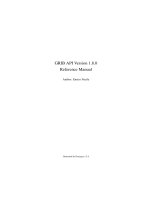
The eta/DYNAFORM software package consists of four programs. These programs represent the preprocessor, solver and post-processor. They are: eta/DYNAFORM, eta/Job Submitter, eta/POST and
eta/3DPlayer.
eta/DYNAFORM is the pre-processor portion of the software package, which is used to construct the
sheet metal forming models. It includes VDA and IGES translators for importing line data and a
complete array of tools for altering or constructing line data and meshing it.
LS-DYNA is the software package’s solver. eta/DYNAFORM has a complete LS-DYNA interface
allowing the user to run LS-DYNA from eta/DYNAFORM.
eta/POST and eta/GRAPH are the post-processing portions of the package. These programs are used
to post-process the LS-DYNA result files from the analysis. eta/POST creates contour, deformation,
FLD, and stress plots and animations with the result files. eta/GRAPH contains functions for
graphically interpreting the same results.
eta/POST
(post-processor)
eta/DYNAFORM
(pre-processor)
LS-DYNA
(solver)
eta/3DPlayer
(post-processor)
Figure 1: Components of eta/DYNAFORM solution package.
Each of the software components has its own manual which should be referenced for further
information on running these programs. These manuals are:
eta/DYNAFORM Application Manual
A comprehensive training manual for using the
eta/DYNAFORM software package for various
applications.
eta/DYNAFORM User’s Manual
A reference guide to the functions contained in
the eta/DYNAFORM program (pre-processor).
LS-DYNA Keyword User’s Manual
A reference guide to the LS-DYNA program
(solver).
eta/POST User’s Manual
A reference guide to the functions contained in
the eta/POST program and eta/GRAPH
program (post-processor).
II
eta/DYNAFORM Application Manual
Error! Use the Home tab to apply 标题 1 to the text that you want to appear here.
INTRODUCTION
Welcome to the eta/DYNAFORM 5.8.1 Application Manual. The eta/DYNAFORM is the unified
version of the Windows and UNIX platforms. This manual is meant to give the user a basic
understanding of finite element modeling for forming analysis, as well as displaying the forming
results. It is by no means an exhaustive study of the simulation techniques and capabilities of
eta/DYNAFORM. For more detailed study of eta/DYNAFORM, the user is urged to attend an
eta/DYNAFORM training seminar.
This manual details a step-by-step sheet metal forming simulation process through AutoSetup
interface process. Users should take the time to learn setup process as each has inherent benefits and
limitations. Completely from the process point of view, AutoSetup in eta/DYNAFORM inherits the
rapidness in QuickSetup, which ensures the user's least operation, The user can define multistage
stamping starting with a simple model, Hydroforming Simulation, Welded blank simulation,
Superplastic Forming, thermal forming, rotary bending and roller hemming meet the user’s needs of
different fields.
The following table outlines the major differences of the traditional setup, the Quick Setup, and the
AutoSetup procedure.
USER SETUP
QUICK SETUP
AUTO SETUP
Manual interface can duplicate any
tooling
configuration:
pads,
multiple tools, etc.
Automated interface limits
flexibility.
There are some inner templates
that enables user to setup all
kinds of operation.
Requires more setup time.
Reduces
time.
Reduces setup time and reduces
the possibility of make mistake.
Manual definition of travel curves
Automated travel curves.
Automated travel curves and
manual definition curve
Geometrical Offset and Contact
Offset.
Contact Offset.
Both Contact Offset
Geometrical Offset.
modeling
setup
and
The exercises provided in the application manual are listed as the following:
1. Single Action Draw: single action / contact offset / draw bead/gravity load.
2. Solid Element Double Action Draw: double action / solid element.
3. Springback and Springback Compensation Analysis: springback / springback compensation.
4. Tube bending and Hydroforming: hydroforming / working direction.
5. Multistage Rotary Bending Simulation: Multistage bending tube / automatically generated
tube and tools.
Note: This manual is intended for the application of all eta/DYNAFORM platforms. Platform
interfaces may vary slightly due to different operating system requirements. This may cause
some minor visual discrepancies in the interface screen shots and your version of
eta/DYNAFORM that should be ignored.
eta/DYNAFORM Application Manual
III
Error! Use the Home tab to apply 标题 1 to the text that you want to appear here.
TABLE OF CONTENTS
Commonly Used Material Type...............................................................................IX
Example 1 Single Action - Fender............................................................................1
Create an eta/DYNAFORM Database........................................................................................2
I.
Start eta/DYNAFORM 5.8.1
2
II.
Open the Database
2
III. Database Unit
3
AUTO SETUP...............................................................................................................................4
I.
New Sheet Forming Setup
4
II.
General
4
III. Blank Definition
5
IV. Blank Material and Property Definition
8
V.
Tools Definition
10
VI. Tools Positioning
19
VII. Process Definition
20
VIII.Control Parameters
22
IX. Define Draw Bead
24
X.
27
Animation
XI. Add Gravity Stage
29
XII. Tools Definition
30
XIII.Process Definition
31
XIV. Submit Job
32
POST PROCESSING (with eta/POST)....................................................................................36
I.
Reading the Results File into the Post Processor
36
II.
Multiple Stage Control
37
III. Deformation
37
IV. FLD
39
V.
40
Thinning
VI. Plot Single Frame
41
VII. View Draw Bead Force Factor
42
VIII.Record an AVI and E3D File
43
eta/DYNAFORM Application Manual
V
Error! Use the Home tab to apply 标题 1 to the text that you want to appear here.
Example 2 Double Action (Solid Element).............................................................45
Create an eta/DYNAFORM Database......................................................................................46
I.
Start eta/DYNAFORM 5.8.1
46
II.
Import File
46
III. Save the Database
47
IV. Database Unit
47
AUTO SETUP.............................................................................................................................48
I.
New Sheet Forming Setup
48
II.
General
49
III. Blank Definition
50
IV. Blank Material and Property Definition
54
V.
55
Tools Definition
VI. Tools Positioning
58
VII. Process Definition
59
VIII.Control Parameters
62
IX. Animation
63
X.
64
Submit Job
POST PROCESSING (with eta/POST)....................................................................................66
I.
Reading the Results File d3plot into the Post Processor
66
II.
Animating Deformation
67
III. Thickness
68
IV. FLD
68
Example 3 Roof Springback Simulation and Springback Compensation..........70
Create an eta/DYNAFORM Database......................................................................................71
I.
Start eta/DYNAFORM 5.8.1
71
II.
Import File
71
III. Save the Database
72
AUTO SETUP.............................................................................................................................74
VI
I.
New Sheet Forming Setup
74
II.
General
74
III. Blank Definition
75
IV. Blank Material and Property Definition
76
V.
77
Boundary Condition
VI. Control Parameters
79
VII. Submit Job
80
eta/DYNAFORM Application Manual
Error! Use the Home tab to apply 标题 1 to the text that you want to appear here.
POST PROCESSING (with eta/POST)....................................................................................82
I.
Reading the Result File d3plot into eta/Post
82
II.
Springback Analysis
83
Springback Compensation Analysis Setup...............................................................................87
I.
Open File
88
II.
Blank Definition
89
III. Tools Definition
92
IV. General Parameters
92
V.
93
Submit for Calculation
VI. Result Check
94
VII. The Second Forming Simulation
97
VIII.Deviation Check
98
IX. Surface Mapping
99
Example 4 Tube Bending and Hydro-forming....................................................101
Create an eta/DYNAFORM Database....................................................................................102
I.
Start eta/DYNAFORM 5.8.1
102
II.
Import File
102
III. Save the Database
102
IV. Database Unit
102
AUTO SETUP...........................................................................................................................103
I.
New Tube Forming Setup
103
II.
General
103
III. Tube Definition
104
IV. Tool Definition (OP10)
107
V.
110
Tools Positioning (OP10)
VI. Process Definition (OP10)
111
VII. Add the Second Stage
113
VIII.Tool Definition (OP20)
114
IX. Process Definition (OP20)
118
X.
119
Control Parameters (OP20)
XI. Add the Third Stage
119
XII. Tube Definition (OP30)
120
XIII.Tool Definition (OP30)
120
XIV. Process Definition (OP30)
121
XV. Control Parameters (OP30)
122
XVI. Animation
122
eta/DYNAFORM Application Manual
VII
Error! Use the Home tab to apply 标题 1 to the text that you want to appear here.
XVII.
Submit Job
123
POST PROCESSING (with eta/POST)..................................................................................125
I.
Reading the Results File d3plot into the Post Processor
125
II.
Multiple Stage Control
126
III. Deformation
126
IV. FLD
127
V.
127
Thickness/Thinning
Example 5 Multistage Rotary Bending Simulation.............................................130
Create an eta/DYNAFORM Database....................................................................................131
I.
Start eta/DYNAFORM 5.8.1
131
II.
Save the Database
131
III. Database Unit
131
AUTO SETUP...........................................................................................................................132
I. New Rotary Bending Simulation Setup
132
II. General
135
III. Tube Definition
136
IV. Tube Material and Property Definition
137
V. Tool Definition
138
VI. Process Definition
139
VII. Control Parameters
140
VIII. Animation
141
IV. Submit Job
142
POST PROCESSING (with eta/POST)..................................................................................143
I.
Reading the Results File d3plot into the Post Processor
143
II.
Multiple Stage Control
143
III. Deformation
144
IV. FLD
146
V.
147
Thickness
VI. Plot Single Frame
148
MORE ABOUT eta/DYNAFORM 5.8.1................................................................149
CONCLUSION..........................................................................................................150
VIII
eta/DYNAFORM Application Manual
Error! Use the Home tab to apply 标题 1 to the text that you want to appear here.
Commonly Used Material Type
At present, LS-DYNA has more than 200 metal/non-metal models for various applications. In sheet
metal forming analysis, rigid body material is used for tooling while rigid-plastic material and elasticplastic material are used for sheet. For elastic-plastic material models, models such as power law
plasticity material, piece-wise linear material, transversely anisotropic elastic-plastic material and 3parameter Barlat material are utilized for the sheet metal stamping forming analysis. eta/DYNAFORM
supports many material models and the commonly used ones are material types 18, 24, 36, 37 and
125, in which types 18 and 24 are isotropic materials while types 36, 37, 39 and 125 are anisotropic
materials. With the development of theory research, more accurate material models will be provided
for the engineering practical application. An introduction of the material models supported by
eta/DYNAFORM is given below.
*MAT_001(*MAT_ELASTIC)
This is Material Type 1. This is an isotropic elastic material and is available for beam, shell, and solid
elements. The user only needs to input density, elastic modulus and Poisson’s ratio.
*MAT_012(*MAT_ISOTROPIC_ELASTIC_PLASTIC)
This is a very low cost isotropic plasticity model for three dimensional solids. In the plane stress
implementation for shell elements, a one-step radial return approach is used to scale the Cauchy stress
tensor to if the state of stress exceeds the yield surface. This approach to plasticity leads to inaccurate
shell thickness updates and stresses after yielding. This is the only model in LS-DYNA for plane
stress that does not default to an iterative approach.
*MAT_018(*MAT_POWER_LAW_PLASTICITY)
This is Material Type 18. This is an isotropic plasticity model with rate effects which uses a power
law hardening rule. It uses the Cowper-Symonds strain rate model as multiplier to consider the strain
rate effects and Mises yield criterion as the yield criterion for material. Since the transverse anisotropy
of material is not considered, this material is only applied in some simple isotropic material analysis.
Generally, the user needs to input the following parameters: elastic modulus of material, mass density,
Poisson’s ratio, strength coefficient, hardening exponent and Cowper-Symonds strain rate, etc.
*MAT_020(*MAT_RIGID)
This is Material 20. Parts made from this material are considered to belong to a rigid body. In
eta/DYNAFORM, this material is used to define the material of toolings and the deformation of
toolings is not considered. The user needs to input the practical tooling density, elastic modulus and
Poisson’s ratio.
*MAT_024(*MAT_PIECEWISE_LINEAR_PLASTICITY)
This is Material Type 24. It is based on the one way tensile test result of material, uses the piecewise
linear function to approach the test result of material plasticity deformation and uses CowperSymonds strain rate model as multiplier to consider the strain rate effect. It also adopts the Mises yield
eta/DYNAFORM Application Manual
IX
Error! Use the Home tab to apply 标题 1 to the text that you want to appear here.
criterion based on isotropic hardening as the material yield criterion. In the stamping forming analysis
of vehicle cover panel, this material model is mainly used in some stamping analysis of isotropy
material. Generally, the user needs to input the following parameters: elastic modulus of material,
mass density, Poisson’s ratio, plastic strain to failure, Cowper-Symonds strain rate coefficient and
piecewise function of material stress and strain.
*MAT_036(*MAT_3-PARAMETER_BARLAT)
This model is used for the anisotropic elastic-plastic materials under plane stress conditions. Since it
considers the effect of both material transverse anisotropy and the anisotropy in sheet plane to the
yield surface, this model can better show the effect of anisotropy to the stamping forming. In fact, this
model is proposed for the sheet metal forming (including stamping forming). If this material model is
used, the user can obtain reliable analysis result without considering the value of transverse anisotropy
coefficient r.
*MAT_037(*MAT_TRANSVERSELY_ANISOTROPIC_ELASTIC_PLASTIC)
The transverse anisotropy has great effect on the stamping forming. Therefore, in the sheet metal
stamping forming analysis, the effect of transverse anisotropy must be considered. This material
model, which is available for the stamping forming analysis of sheet with a transverse anisotropy
coefficient greater than 1, uses the Hill yield criterion and considers the effect of transverse anisotropy
to the yield surface of material, but neither the effect of anisotropy in sheet plane nor the strain rate
effect is considered. However, if this material is used for the sheet stamping analysis with a transverse
anisotropy coefficient less than 1, great error may be generated and the result is even worse than the
one using Mises yield criterion without considering the transverse anisotropy effect. As shown in the
research, for sheet stamping conditions with a transverse anisotropy coefficient less than 1, the correct
calculation result can only be obtained by using non-quadratic yield criterion. For sheet stamping
forming analysis with a transverse anisotropy coefficient greater than 1, the correct calculation result
can be obtained by using this material model and all the 3-parameter Barlat material model. In
addition, this material model is only available for shell element analysis. Generally, the user needs to
input the following parameters: elastic modulus of material, mass density, Poisson’s ratio and
transverse anisotropy coefficient r, etc.
*MAT_039(*MAT_FLD_TRANSVERSELY_ANISOTROPIC)
This model is for simulating sheet forming processes with anisotropic material. Only transverse
anisotropy can be considered. Optionally, an arbitrary dependency of stress and effective plastic strain
can be defined via a load curve. A Forming Limit Diagram (FLD) can be defined using a curve and is
used to compute the maximum strain ratio. This plasticity model is fully iterative and is available only
for shell elements.
*MAT_125(*MAT_KINEMATIC_HARDENING_TRANSVERSELY_ANISOTROPIC)
This material model combine Yoshida non-linear kinematic hardening rule with M37. This theory
needs two surfaces describing the hardening rule: the yield surface and the bounding surface. In the
forming process, the yield surface does not change in size, but its center moves with deformation; the
bounding surface changes both in size and location. This model also allows the change of Young’s as
proposed by Yoshida.
X
eta/DYNAFORM Application Manual
Error! Use the Home tab to apply 标题 1 to the text that you want to appear here.
Example 1
Single Action - Fender
eta/DYNAFORM Application Manual
1
Error! Use the Home tab to apply 标题 1 to the text that you want to appear here.
Create an eta/DYNAFORM Database
I. Start eta/DYNAFORM 5.8.1
For workstation/Linux users, enter the command “df581” (default) from a UNIX shell. For PC users,
double click the eta/DYNAFORM icon from the desktop.
After starting eta/DYNAFORM, a default database Untitled.df is created. The user needs to import
CAD or CAE model to the database to start working.
II. Open the Database
From the menu bar, select FileOpen to open the Open File dialog box, as illustrated in Figure 1 .1.
Select the database file fender.df and click Open to display the model illustrated in Figure 1 .2.
Figure 1.1 Open file dialog box
2
eta/DYNAFORM Application Manual
Error! Use the Home tab to apply 标题 1 to the text that you want to appear here.
Figure 1.2 Illustration of fender model
III.Database Unit
From the menu bar, select UserSetupAnalysis Configuration. The default unit system for a new
eta/DYNAFORM database is mm, Ton, Sec and N.
eta/DYNAFORM Application Manual
3
Error! Use the Home tab to apply 标题 1 to the text that you want to appear here.
AUTO SETUP
After finishing the preparation of model, Click Sheet Forming option from AutoSetup menu to
display Sheet Forming Setup.
Figure 1.3 AutoSetup menu
I. New Sheet Forming Setup
Clicking Sheet Forming menu, the New Sheet Forming dialog box appears for the user to define the
basic setup parameters, as illustrated Figure 1 .4.
Figure 1.4 Sheet Forming Setup dialog box
1.
Input blank thickness: 0.7 (mm).
2.
Select process type: Single Action.
3.
Select original die face: Upper.
4.
Click OK to display the Sheet Forming interface.
II. General
After entering General interface, you do not need to modify any parameters except for changing the
Title into Fender_forming. See Figure 1 .5.
4
eta/DYNAFORM Application Manual
Error! Use the Home tab to apply 标题 1 to the text that you want to appear here.
Figure 1.5 General interface
III.Blank Definition
1.
First, click Blank tab to display the blank definition interface.
2.
Then, click Define geometry button from Geometry field in the blank definition interface.
See Figure 1 .6.
eta/DYNAFORM Application Manual
5
Error! Use the Home tab to apply 标题 1 to the text that you want to appear here.
Figure 1.6 Define blank
3.
The Blank Generator dialog box illustrated in Figure 1 .7 is displayed.
Figure 1.7 Blank generator dialog box
6
4.
Click the Add Part button to select the BLANK part from the SELECT PART dialog box
illustrated in Figure 1 .8.
5.
After selecting the part, click OK button to return to the Blank Generator dialog box. As
illustrated in Figure 1 .9, the BLANK part has been added to the list of blank.
6.
Click the Exit button to return to the blank definition interface. Now, the color of Blank tab
is changed from RED to BLACK. See Figure 1 .10.
eta/DYNAFORM Application Manual
Error! Use the Home tab to apply 标题 1 to the text that you want to appear here.
Figure 1.8 Select Part dialog box
eta/DYNAFORM Application Manual
Figure 1.9 Blank generator
7
Error! Use the Home tab to apply 标题 1 to the text that you want to appear here.
Figure 1.10 Blank definition interface
IV. Blank Material and Property Definition
Once the BLANK part is defined, the program automatically assigns a default blank material and
relative property. You can also click the BLANKMAT button illustrated in Figure 1 .10 to edit
material definition.
Now, you continue to select a material from the material library, as shown in Figure 1 .12.
Note: If there is no desired material in the Material Library, the user can create a new material or
edit the selected material.
8
eta/DYNAFORM Application Manual
Error! Use the Home tab to apply 标题 1 to the text that you want to appear here.
Figure 1.11 Material dialog box
Figure 1.12 United States generic material library
eta/DYNAFORM Application Manual
9