Suspension system _KIA FORTE
Bạn đang xem bản rút gọn của tài liệu. Xem và tải ngay bản đầy đủ của tài liệu tại đây (9.06 MB, 43 trang )
FORTE/FORTE KOUP(TD) > 2010 > G 2.0 DOHC > Suspension System
Suspension System > General Information > Specifications
Specifications
Front Suspension
Item Specification
Suspension type MacPherson Strut
Shock absorber Type Gas
Coil spring Free Height [I.D. color]
319.84mm (RED - 2)
326.74mm (GRAY - 2)
Rear Suspension
Item Specification
Suspension type Torsion Beam Axle
Shock absorber Type Gas
Coil spring Free Height [I.D. color]
288.63mm (GREEN)
272.73mm (BLUE/RED - 1)
Wheel & Tire
Item Specification
Wheel
Aluminum
5.0J x 15
6.0J x 16
7.0J x 17
Steel 5.5J x 15
Tire
185/70 R15
195/65 R15
205/60 R16
215/50 R17
215/45 R17
Tire pressure 2.2kg/cm² (32psi)
Wheel Alignment
Item
Specification
4DR/5DR 2DR
Front
Toe-in
Total 0.12°±0.18° 0.4°±0.2°
Individual 0.06°±0.09° 0.2°±0.1°
Camber -0.64°±0.5° -0.81°±0.5°
Caster 4.38°±0.5° 4.94°±0.5°
King-pin 13.61°±0.5° 14.01°±0.5°
Rear Toe-in Total 0.4°±0.2° 0.4°±0.2°
1 of 43
9/16/2011 9:08 PM
==============================================================================================================================
Individual 0.2°±0.1° 0.2°±0.1°
Camber -1.5°±0.5° -1.5°±0.5
Tightening Torques
Front Suspension
Item
Tightening torque (kgf.m)
Nm Kgf.m lb-ft
Hub nuts 90 ~ 110 9 ~ 11 65 ~ 80
Lower arm to sub frame 140 ~ 160 /100 ~ 120 14 ~ 16 /10 ~ 12 101 ~ 115 /72 ~ 87
Tie rod end castle nut 24 ~ 34 2.4 ~ 3.4 72 ~ 87
Steering gear box to
sub frame
MDPS 50 ~ 65 5 ~ 6.5 36 ~ 47
HPS 60 ~ 80 6 ~ 8 43 ~ 58
Stabilizer bar to stabilizer link 100 ~ 120 10 ~ 12 72 ~ 87
Stabilizer bar to sub frame 45 ~ 55 4.5 ~ 5.5 32 ~ 40
Stabilizer bar to front strut assembly 100 ~ 120 10 ~ 12 72 ~ 87
Front strut assembly to front axle 140 ~ 160 14 ~ 16 101 ~ 115
Rear Suspension
Item
Tightening torque (kgf.m)
Nm Kgf.m lb-ft
Hub nuts 90 ~ 110 9.0 ~ 11.0 65 ~ 80
Shock absorber to body 100 ~ 120 10.0 ~12.0 72 ~ 87
Shock absorber to torsion beam axle 100 ~ 120 10.0 ~12.0 72 ~ 87
Torsion beam axle to body 100 ~ 120 10.0 ~ 12.0 72 ~ 87
Suspension System > General Information > Special Service Tools
Special Service Tools
Tool (Number and Name) Illustration Use
09546-26000
Strut spring compressor
Compression of coli spring
09568-2J100
Ball joint puller
Remover of ball joint
2 of 43
9/16/2011 9:08 PM
==============================================================================================================================
09568-4A000
Ball joint puller
Separation of tie-rod end ball joint
Suspension System > General Information > Troubleshooting
Troubleshooting
Symptom Possible cause Remedy
Hard steering Improper front wheel alignment
Excessive turning resistance of lower arm ball joint
Low tire pressure
No power assist
Correct
Replace
Adjust
Repair and replace
Poor return of steering
wheel to center
Improper front wheel alignment Correct
Poor or rough ride
Improper front wheel alignment
Malfunctioning shock absorber
Broken or worn stabilizer
Broken or worn coil spring
Worn lower arm bushing
Correct
Repair or replace
Replace
Replace
Replace the lower arm
assembly
Abnormal tire wear Improper front wheel alignment
Improper tire pressure
Malfunctioning shock absorber
Correct
Adjust
Replace
Wandering Improper front wheel alignment
Poor turning resistance of lower arm ball joint
Loose or worn lower arm bushing
Correct
Repair
Retighten or replace
Vehicle pulls to one
side
Improper front wheel alignment
Excessive turning resistance of lower arm ball joint
Broken or worn coil spring
Bent lower arm
Correct
Replace
Replace
Repair
Steering wheel shimmy Improper front wheel alignment
Poor turning resistance of lower arm ball joint
Broken or worn stabilizer
Worn lower arm bushing
Malfunctioning shock absorber
Broken or worn coil spring
Correct
Replace
Replace
Replace
Replace
Replace
Bottoming Broken or worn coil spring
Malfunctioning shock absorber
Replace
Replace
Wheel /tire noise, vibration and harshness concerns are directly related to vehicle speed and are not generally affected by
acceleration, coasting or decelerating. Also, out-of-balance wheel and tires can vibrate at more than one speed. A
vibration that is affected by the engine rpm, or is eliminated by placing the transmission in Neutral is not related to the tire
and wheel. As a general rule, tire and wheel vibrations felt in the steering wheel are related to the front tire and wheel
assemblies. Vibrations felt in the seat or floor are related to the rear tire and wheel assemblies. This can initially isolate a
concern to the front or rear.
Careful attention must be paid to the tire and wheels. There are several symptoms that can be caused by damaged or
3 of 43
9/16/2011 9:08 PM
==============================================================================================================================
worn tire and wheels. Perform a careful visual inspection of the tires and wheel assemblies. Spin the tires slowly and
watch for signs of lateral or radial runout. Refer to the tire wear chart to determine the tire wear conditions and actions
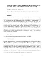
Wheel and tire diagnosis
Rapid wear at the center Rapid wear at both shoulders Wear at one shoulder
• Center-tread down to fabric due to
excessive over inflated tires
• Lack of rotation
• Excessive toe on drive wheels
• Heavy acceleration on drive
• Under-inflated tires
• Worn suspension components
• Excessive cornering speeds
• Lack of rotation
• Toe adjustment out of specification
• Camber out of specification
• Damaged strut
• Damaged lower arm
Partial wear Feathered edge Wear pattern
• Caused by irregular burrs on brake
drums
• Toe adjustment out of specification
• Damaged or worn tie rods
• Damaged knuckle
• Excessive toe on non-drive wheels
• Lack of rotation
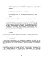
Suspension System > Front Suspension System > Components and Components Location
Components
4 of 43
9/16/2011 9:08 PM
==============================================================================================================================
1. Sub frame
2. Strut Assembly
3. Lower Arm
4. Drive Shaft
5. Stabilizer Bar
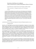
Suspension System > Front Suspension System > Front Strut Assembly > Components and
Components Location
Components
5 of 43
9/16/2011 9:08 PM
==============================================================================================================================
1. Nuts
2. Lock nut
3. Insulator
4. Strut bearing
5. Spring upper pad
6. Strut dust cover & bumper rubber
7. Coil spring
8. Spring lower pad
9. Piston road
10. Strut assembly
11. Spring lower seat
Suspension System > Front Suspension System > Front Strut Assembly > Repair
procedures
Replacement
1. Remove the front wheel & tire.
Tightening torque Nm (kgf.m, lb-ft) :
90 ~ 110 (9.0 ~ 11.0, 65 ~ 80)
2. Remove the brake hose and the wheel speed sensor bracket from the front strut assembly by loosening the mounting
bolts.
6 of 43
9/16/2011 9:08 PM
==============================================================================================================================
3. Disconnect the stabilizer link with the front strut assembly after loosening the nut.
Tightening torque Nm (kgf.m, lb-ft) :
100 ~ 120 (10.0 ~ 12.0, 72 ~ 87)
4. Remove the cap and than loosen the strut mounting nuts.
5. Disconnect the front strut assembly with the knuckle by loosening the bolt & nut.
Tightening torque Nm (kgf.m, lb-ft) :
140 ~ 160 (14.0 ~ 16.0, 101 ~ 115)
7 of 43
9/16/2011 9:08 PM
==============================================================================================================================
6. Installation is the reverse of removal.
Disassembly
1. Using the special tool (09546-26000), compress the coil spring (A) until there is only a little tension of the spring on the
strut.
2. Remove the self-locking nut (C) from the strut assembly (B).
3. Remove the insulator, spring seat, coil spring and dust cover from the strut assembly.
Inspection
1. Check the strut insulator bearing for wear or damage.
2. Check rubber parts for damage or deterioration.
3. Compress and extend the piston rod (A) and check that there is no abnormal resistance or unusual sound during
operation.
8 of 43
9/16/2011 9:08 PM
==============================================================================================================================
Reassembly
1. Install the spring lower pad (D) so that the protrusions (A) fit in the holes (C) in the spring lower seat (B).
2. Compress coil spring using special tool (09546-26000).
Install compressed coil spring into shock absorber.
1) Indicated two identification color marks on the coil spring one follows model option (see page SS-2) the other
follows load classification according to the below.
Pay attention to distiuguish between the two marks and then install them.
2) Install the coil spring wth the idemtification mark directed toward the knuckle.
3. After fully extending the piston rod, install the spring upper seat and insulator assembly.
4. After seating the upper and lower ends of the coil spring (A) in the upper and lower spring seat grooves (B) correctly,
tighten new self-locking nut temporarily.
5. Remove the special tool (09546-26000).
6. Tighten the self-locking nut to the specified torque.
Tightening torque :
50 ~ 70 Nm (5 ~7 kgf·m, 36 ~ 50 lb-ft)
Suspension System > Front Suspension System > Front Lower Arm > Repair procedures
Replacement
1. Remove the front wheel & tire.
Tightening torque Nm (kgf.m, lb-ft) :
90 ~ 110 (9.0 ~ 11.0, 65 ~ 80)
2. Remove the lower arm ball joint mounting bolts.
Tightening torque Nm (kgf.m, lb-ft) :
100 ~ 120 (10.0 ~ 12.0, 72 ~ 87)
9 of 43
9/16/2011 9:08 PM
==============================================================================================================================
3. Remove the lower arm mounting bolts.
Tightening torque Nm (kgf.m, lb-ft) :
100 ~ 120 (10.0 ~ 12.0, 72 ~ 87)
Tightening torque Nm (kgf.m, lb-ft) :
140 ~ 160 (14.0 ~ 16.0, 101 ~ 115)
4. Using the special tools (09214-32000 & 09216-211000), remove the bushing from the lower arm.
10 of 43
9/16/2011 9:08 PM
==============================================================================================================================
5. Apply soap solution to the following parts.
A. Outer surface of the bushing.
B. Inner surface of the lower bushing mounting part.
6. Using the special tools (09214-32000 & 09216-21100), install the busing on the lower arm. Remove old bushing on the
lower arm.
Remove bushing in the direction of arrow shawn.
Separation force is over 800Kg
7. Installation is the reverse of removal.
Suspension System > Front Suspension System > Front Stabilizer Bar > Repair procedures
Replacement
11 of 43
9/16/2011 9:08 PM
==============================================================================================================================
1. Remove the front wheel & tire.
Tightening torque Nm (kgf.m, lb-ft) :
90 ~ 110 (9.0 ~ 11.0, 65 ~ 80)
2. Disconnect the stabilizer link with the front strut assembly after loosening the nut.
Tightening torque Nm (kgf.m, lb-ft) :
100 ~ 120 (10.0 ~ 12.0, 72 ~ 87)
3. Disconnect the tie-rod end with the knuckle using a SST (09568-2J100).
4. Remove the two bolts for lower arm ball joint.
5. Loosen the bolt and then disconnect the universal joint assembly from the pinion of the steering gear box.
12 of 43
9/16/2011 9:08 PM
==============================================================================================================================
Keep the neutral-range to prevent the damage of the clock spring inner cable when you handlethe steering wheel.
6. Remove the cross member from the body by loosening the mounting bolts and nuts.
7. Remove the stabilizer from the cross member by loosening the bracket mounting bolts.
Tightening torque Nm (kgf.m, lb-ft) :
13 of 43
9/16/2011 9:08 PM
==============================================================================================================================
45 ~ 55 (4.5 ~ 5.5, 32 ~ 40)
8. Installation is the reverse of removal.
Inspection
1. Check the bushing for wear and deterioration.
2. Check the front stabilizer bar for deformation.
3. Check the front stabilizer link ball joint for damage.
Suspension System > Front Suspension System > Front Cross Member > Repair
procedures
Replacement
1. Remove the sub frame. (Refer to front stabilizer)
2. Remove the front lower arm.
3. Remove the front strut assembly.
4. Remove the front stabilizer.
5. Remove the steering gear box.
6. Installation is the reverse of removal.
Suspension System > Rear Suspension System > Components and Components Location
Components
14 of 43
9/16/2011 9:08 PM
==============================================================================================================================
1. Torsion beam axle
2. Rear shock absorber
3. Coil spring assembly
Suspension System > Rear Suspension System > Rear Shock Absorber > Components and
Components Location
Components
15 of 43
9/16/2011 9:08 PM
==============================================================================================================================
1. Dust cover
2. Shock absorber
Suspension System > Rear Suspension System > Rear Shock Absorber > Repair procedures
Replacement
1. Remove the rear wheel & tire.
Tightening torque Nm (kgf.m, lb-ft) :
90 ~ 110 (9.0 ~ 11.0, 65 ~ 80)
2. Remove the rear shock absorber from the frame by loosening the bolt.
Tightening torque Nm (kgf.m, lb-ft) :
100 ~ 120 (10.0 ~ 12.0, 72 ~ 87)
16 of 43
9/16/2011 9:08 PM
==============================================================================================================================
3. Remove the rear shock absorber from the torsion beam axle by loosening the nut.
Tightening torque Nm (kgf.m, lb-ft) :
100 ~ 120 (10.0 ~ 12.0, 72 ~ 87)
4. Installation is the reverse of removal.
Inspection
1. Check the components for damage or deformation.
2. Compress and extend the piston and check that there is no abnormal resistance or unusual sound during operation.
Suspension System > Rear Suspension System > Rear Coil Spring > Components and
Components Location
Components
17 of 43
9/16/2011 9:08 PM
==============================================================================================================================
1. Spring upper pad
2. Spring
3. Spring lower pad
Suspension System > Rear Suspension System > Rear Coil Spring > Repair procedures
Replacement
1. Remove the rear wheel & tire.
Tightening torque Nm (kgf.m, lb-ft) :
90 ~ 110 (9.0 ~ 11.0, 65 ~ 80)
2. Remove the rear shock absorber from the torsion beam axle by loosening the nut.
18 of 43
9/16/2011 9:08 PM
==============================================================================================================================
Tightening torque Nm (kgf.m, lb-ft) :
100 ~ 120 (10.0 ~ 12.0, 72 ~ 87)
3. Installation is the reverse of removal.
Inspection
1. Check the coil spring for crack and deformation.
2. Check the coil spring pad for damage and deformation.
Suspension System > Rear Suspension System > Rear torsion beam axle > Components
and Components Location
Components
19 of 43
9/16/2011 9:08 PM
==============================================================================================================================
1. Rear torsion beam axle
Suspension System > Rear Suspension System > Rear torsion beam axle > Repair
procedures
Replacement
1. Remove the rear wheel & tire.
Tightening torque Nm (kgf.m, lb-ft) :
90 ~ 110 (9.0 ~ 11.0, 65 ~ 80)
2. Loosen the bolts (A).
Tightening torque Nm (kgf.m, lb-ft) :
65 ~ 75 (6.5 ~ 7.5, 47 ~ 54)
20 of 43
9/16/2011 9:08 PM
==============================================================================================================================
3. Loosen the screw (B).
4. Remove the wheel speed sensor cable and the loosening the mounting bolts.
Tightening torque Nm (kgf.m, lb-ft) :
60 ~ 70 (6.0 ~ 7.0, 43 ~ 50)
5. Remove the wheel speed sensor cable and parking brake cable mounting bracket bolts.
21 of 43
9/16/2011 9:08 PM
==============================================================================================================================
6. Remove the rear hub unit bearing.
7. Remove the parking brake cable.
8. Remove the rear shock absorber from the torsion beam axle by loosening the nut.
Tightening torque Nm (kgf.m, lb-ft) :
100 ~ 120 (10.0 ~ 12.0, 72 ~ 87)
9. Remove the torsion axle from the body loosening the bolts.
22 of 43
9/16/2011 9:08 PM
==============================================================================================================================
10. Installation is the reverse of removal.
Suspension System > Tires/Wheels > Tire > Repair procedures
Tire Wear
1. Measure the tread depth of the tires.
Tread depth [limit] : 1.6 mm (0.063 in)
2. If the remaining tread depth (A) is less than the limit, replace the tire.
When the tread depth of the tires is less than 1.6 mm(0.063 in), the wear indicators (B) will appear.
Suspension System > Tires/Wheels > Wheel > Repair procedures
Hub Nut Tightening Sequence
Tighten the hub nuts as follows.
Tightening torque :
90 ~ 110N.m (9.0 ~ 11.0kgf.m, 65 ~ 80lb-ft)
When using an impact gun, final tightening torque should be checked using a torque wrench.
Suspension System > Tires/Wheels > Alignment > Repair procedures
Front Wheel Alignment
23 of 43
9/16/2011 9:08 PM
==============================================================================================================================
When using a commercially available computerized wheel alignment equipment to inspect the front wheel alignment,
always position the vehicle on a level surface with the front wheels facing straight ahead.
Prior to inspection, make sure that the front suspension and steering system are in normal operating condition and
that the tires are inflated to the specified pressure.
Toe
B - A > 0: Toe in (+)
B - A < 0: Toe out (-)
Toe Adjustment
1. Loosen the tie rod end lock nut.
2. Remove the bellows clip to prevent the bellows from being twisted.
3. Adjust the toe by screwing or unscrewing the tie rod. Toe adjustment should be made by turning the right and left tie
rods by the same amount.
Toe-in
4DR/5DR
Total : 0.12°±0.18°
Individual : 0.06°±0.09°
2DR
Total : 0.4°±0.2°
Individual : 0.2°±0.1°
4. When completing the toe adjustment, install the bellows clip and tighten the tie rod end lock nut to specified torque.
Tightening torque :
50 ~ 55N.m (5.0 ~ 5.5kgf.m, 36 ~ 40lb-ft)
24 of 43
9/16/2011 9:08 PM
==============================================================================================================================
Camber and Caster
Camber and Caster are pre-set at the factory, so they do not need to be adjusted. If the camber and caster are not within
the standard value, replace or repair the damaged parts and then inspect again.
Camber angle
4DR : -0.64°±0.5°
2DR : -0.81°±0.5°
Caster angle
4DR : 4.38°±0.5°
2DR : 4.94°±0.5°
Rear Wheel Alignment
When using a commercially available computerized wheel alignment equipment to inspect the rear wheel alignment,
always position the vehicle on a level surface.
Prior to inspection, make sure that the rear suspension system is in normal operating condition and that the tires are
inflated to the specified pressure.
Toe
B - A > 0: Toe in (+)
B - A < 0: Toe out (-)
Toe is pre-set at the factory, so it does not need to be adjusted. If the toe is not within the standard value, replace or
repair the damaged parts and then inspect again.
Toe-in
4DR
Total : 0.4°±0.2°
Individual : 0.2°±0.1°
2DR
Total : 0.4°±0.2°
Individual : 0.2°±0.1°
Camber
Camber is pre-set at the factory, so it does not need to be adjusted. If the camber is not within the standard value,
replace or repair the damaged parts and then inspect again.
Camber
4DR / 2DR : -1.5°±0.5°
25 of 43
9/16/2011 9:08 PM
==============================================================================================================================