Combustion and emission characteristics of a natural gas fueled diesel engine with EGR
Bạn đang xem bản rút gọn của tài liệu. Xem và tải ngay bản đầy đủ của tài liệu tại đây (734.3 KB, 12 trang )
Energy
Conversion
and
Management
64
(2012)
301–312
Contents lists available at SciVerse
ScienceD i
rect
Energy Conversion and
Man
agement
j o u r n
a
l
h o m e p a g e :
www
.
e
l
s
e
v
i e
r
.
c
o
m /
l
o
c
a
t e /
e n c
o n m
a
n
Combustion
and
emission characteristics
of a
natural gas-fueled diesel
engine
with
EGR
M.M.
Abdelaal,
A.H.
Hegab
⇑
Department
of
Mechanical Engineering, Al-Azhar University,
Cairo
11371, Egypt
a
r
t
i
c
l
e
i
n
f
o
Article
history:
Received
18 October 2011
Received in revised form 22
May
2012
Accepted 27 May 2012
Available
online 26 September
2012
Keywords:
Dual-fuel
engine
Natural gas
Diesel fuel
Pilot
ignited
EGR
Emissio
ns
a
b
s
t
r
a
c
t
The
use
of
natural
gas as a
partial supplement
for
liquid diesel
fuel is a
very promising solution
for
reduc-
ing
pollutant emissions, particularly nitrogen oxides
(NOx)
and particulate matters
(PM),
from conven- tional diesel engines.
In
most applications
of
this technique, natural
gas
is
inducted
or
injected
in
the
intake manifold to mix uniformly with
air,
and the
homogenous natural gas–air mixture
is
then intro-
duced to the cylinder
as a
result
of
the
engine suction.
This
type
of
engines, referred to
as
dual-fuel engines, suffers from lower thermal efficiency
and higher
carbon monoxide
(CO)
and unburned hydrocarbon
(HC)
emissions; particularly at
part load.
The
use of
exhaust
gas
recirculation
(EGR) is
expected to partially resolve these
problems and to provide further
reduction
in NOx
emission
as
w
ell.
In
the present experimental study,
a
single-cylinder direct injection
(DI)
diesel engine has
been prop-
erly modified to run
on
dual-fuel mode with natural
gas as a
main
fuel
and diesel
fuel as a
pilot,
with the
ability to employ variable amounts
of EGR.
Comparative results
are
given
for
various operating modes;
conventional diesel mode, dual-fuel mode without
EGR,
and dual-fuel mode with variable amounts of
EGR,
at different operating conditions;
revealing the effect
of
utilization
of EGR on
combustion process
and exhaust emission
characteristics
of a
pilot ignited natural
gas
diesel engine.
2012 Elsevier
Ltd. All
rights
reserved.
1.
Introduction
With the increasing concern regarding diesel engines
emissions,
including
NOx,
smoke, and
PM,
and the rising
cost
of
the liquid die-
sel fuel as well,
the utilization
of
alternative fuels
in
diesel engines
seems
to
present
attractive solution
for
both environmental and
economical
problems
.
Among the alternative
fuels,
natural
gas is very
promising and
highly attractive. Beside
its
availability
in
several areas
worldwide
at encouraging prices, natural
gas is
eco-friendly
fuel
that
has
clean
nature
of
combustion.
It can
substantially reduce the
NOx
emis-
sions
by
approximately
50–80%
while produces almost zero smoke
and
PM;
which
is
extremely difficult
to
achieve
in DI
diesel en-
gines.
It
can also
contribute
to
the reduction
of
carbon dioxide
(CO
2
)
emissions, due
to
the
low
carbon-to-hydrogen ratio.
In
addi-
tion, natural
gas has a
high octane number, and hence
high autoig-
nition temperature. Therefore,
it is
suitable
for
engines with
relatively high compression ratio without
experiencing the knock
phenomenon. Moreover,
it
mixes
uniformly with
air,
resulting in
efficient combustion
to
such
an
extent that
it can
yield
a
high
ther-
⇑
Corresponding author.
Tel.: +20
100 8053552; fax:
+20
222 601706.
E-mail address:
(A.H.
Hegab).
mal
efficiency comparable
to
the diesel version at higher
loads
[1–3]
.
The
most common natural gas–diesel operating mode
is
re-
ferred
to as
the pilot ignited natural
gas
diesel
engine; where most
of
the engine power output
is
provided
by
the gaseous
fuel,
while a
pilot amount
of
the liquid diesel
fuel,
represents around
20% of
the
total
fuel
supplied
to
the
engine at
full load
operation (energy ba-
sis), is
injected
near the end
of
the compression stroke
to act as
an
ignition
source
of
the gaseous fuel–air mixture.
The
injected spray
ignites several points
in
the gaseous fuel–air mixture,
forming
multi flame-fronts that travel throughout the
entire mixture. The engine power output
is
controlled
by
changing the amount
of
the
primary gaseous
fuel,
while the
pilot
fuel
quantity
is
kept constant
[4–6]
.
In
some applications, natural
gas is
directly injected into
the cyl-
inder shortly before the end
of
the compression
stroke.
This
tech-
nique provides better
fuel
economy
and more efficient
combustion, and maintains the power
output and the thermal effi-
ciency
of an
equivalently-sized
conventional diesel engine
[7,8]
.
However
,
direct injection
of
natural
gas
requires the
developmen
t
of
special high-
pressure gaseous injectors.
Therefore,
in
most appli-
cations
to
date, natural
gas is
inducted
or
injected
in
the intake
manifold
to mix
uniformly with
air,
and the homogenous
natural
gas–air mixture
is
then introduced
to
the cylinder
as a
result of
0196-8904/$ - see front matter 2012 Elsevier
Ltd. All
rights reserved.
/>Nomenc
lature
Latin
C
p
specific heat
at
constant pressure
(J/kg
k)
C
v
specific heat
at
constant volume
(J/kg
k)
m mass (kg)
m
_
mass
flow
rate (kg/h)
p
in-cylinder pressure
(N/m
2
)
Q
heat
(J)
V
cylinder volume
(m
3
)
Greek
c
specific heat ratio (–)
h
crank angle
(
)
/
equivalence ratio (–)
Supersc
ripts
stoic
stoichiomet
ric
Subscript
s
D
diesel
i
intake
NG
natural gas
tot
total
Abbrevi
ations
ABDC
after bottom dead center
A/D
analog-to-
digital
AFR air to fuel
ratio
(kg
air/kg fuel)
ATDC
after
top
dead center
BBDC
before bottom dead center
BTDC
before
top
dead center
CA
crank angle
CAD
crank angle degree
CI
compression ignition
C/H
carbon
to
hydrogen ratio
CNG
compressed natural gas
CO
carbon monoxide
CO
2
carbon dioxide
COV
coefficient
of
variance
DI
direct injection
EGR
exhaust
gas
recircul
ation
EI
emission index
HC
unburned
hydrocarbo
n
HHR
heat release rate
(J/CAD)
NDIR
non-dispersive infrared
NO
nitric oxide
NO
2
nitrogen dioxide
NOx
nitrogen oxides
PC
personal
compute
r
PM
particulate matters
ROPR
rate
of
pressure
rise
(bar/CAD)
TDC top
dead center
the engine suction.
A
typical four-stroke engine
has one
suction
stroke
per cycle
while there
is no
suction
in
the other three stokes.
For
that reason, the measurement
of
the gaseous
fuel
flowrate be-
comes
a
point
of
doubt and should
be
emphasized and carefully
treated,
in
order
to
avoid the
use of
inappropriate
measureme
nt
technique that does
not
take into account that the actual gaseous
fuel
consumption takes place
in only one
stroke
per
cycle;
i.e.
the
suction stroke.
As
the gaseous
fuel
should
be
inducted into the cyl-
inder
as a
result
of
the engine suction
only, its
pressure should be
kept
as low as
possible
to
prevent the
flow
while there
is no
suction.
Some
flowrate measuring instruments, such
as
rotary
flowmeters
and variable area flowmeters, involve
a
considerable
pressure drop,
and therefore they require the increase
of gas
pressure
in
order to
overcome this pressure drop.
The
increase
of
gas
pressure may lead
to
continuous
gas
supply during the
four
strokes while the actual
consumption takes place
in only one
stroke.
In
such
a case,
the mea-
sured value would
not
represent
the actual consumption. Hence,
these instruments cannot
be
used
in
measuring the gaseous fuel
flowrate
in
reciprocating
internal combustion engines.
During the
last
years, the implementation
of
pilot ignited
natural
gas
diesel engines
has
been
investigated
,
experimentally
and theo-
retically,
by
numerous researchers. Combustion
and
exhaust emis-
sion
characteristics
of
this type
of
engines have
been examined in
various studies [9–13]. Several predictive
models have
also
been
developed
in
order
to
provide better
understanding
of
the combus-
tion process
in
gas–diesel engines
and some
of
their
performanc
e
features and emission
characteristics [14–16]. Moreover,
the effects
of
some important
parameters, such
as
pilot diesel
fuel
quantity, pi-
lot
injection
timing, natural
gas
percentage, natural
gas
composi-
tion, and
intake
air
temperature have
also
been studied
[17–21]
.
It has
been reported that the main drawback
of
this operating
mode,
in
contrast with conventional diesel mode,
is
the negative
effect
on
engine efficiency,
CO
and
HC
emissions, particularly
at
low
and intermediate loads.
At
high
load,
the improvement
in
gas-
eous
fuel
utilization leads
to
corresponding improvement
in
both
engine performance and
CO
emissions, and the thermal efficiency
becomes comparable
to
that observed under conventional diesel
operation
.
Alternating some engine parameters, such
as
the in-
crease
of
pilot
fuel
quantity and the advance
of
injection timing,
has
positive effect
on
engine performance,
CO
and
HC
emissions,
but
it
adversely affects
NOx
emission
.
In
order
to
overcome these drawbacks while provide further
reduction
in NOx
emission at the same time,
EGR
may
be
used.
By
employing
EGR,
portion
of
the unburned
gas in
the exhaust
from the previous
cycle is
recirculated
,
and expected
to
possibly
reburn
in
the succeeding cycle; resulting
in a
reduction
in
the un-
burned
fuel
with simultaneous improvement
in
thermal efficiency
and reduction
in CO.
Furthermore, the application
of EGR
involves
replacement
of
some
of
the inlet
air
with
EGR. The
consequences of
this replacement include
a
dilution
of
the inlet charge and
an
in-
crease
in its
heat capacity. These
two effects lower the combustion
temperature.
The
simultaneous reductions
of
oxygen
concentr
a-
tion, combustion
temperature
,
and flame propagation speed re-
duce
NOx
substantially. However,
as NOx is
reduced,
PM
is
increased; due
to
the lowered oxygen concentration. When
EGR
further increases, the engine operation reaches zones with higher
instabilities, increased carbonaceous emissions, and even power
losses.
[22–25]
.
The aim of
the present work
is to
investigate,
experime
ntally,
the potentials
of
the
use of EGR in
pilot ignited natural
gas
diesel
engines.
A
complete
set of
measurements
is
conducted
for
various
engine operating mode; diesel, plain dual-fuel (without
EGR),
and
dual-fuel with
EGR,
at different operating conditions. Detailed
re-
sults
are
given
for
combustion characteristics, engine performance,
and exhaust emission analysis.
2.
Experimental apparatus and conditions
2.1.
Experimental
apparatus
The
present study
has
been conducted
on a
Petter
PH1W
single
cylinder, naturally aspirated, four-stroke, water cooled,
high speed,
M.M.
Abdelaal,
A.H.
Hegab
/
Energy Conversion and Management
64
(2012) 301–
3
Table 1
Engine specifications.
Model Petter PH1W
diesel engine
Engine configuration Single cylinder, four-
stroke, naturally aspirated,
water cooled
Bore 87.3
mm
Stroke 110 mm
Compression ratio 16.5:1
Rated power and speed
(B.S.
continuous rating)
8.2
bhp
@
2000 rpm
Fuel injection system Direct injection (DI)
Injection pressure 200 bar
Number
of
nozzle holes 3
Nozzle hole diameter 0.25
mm
Spray
angle
120
Valve timing Opening Closing
Intake
4.5 BTDC
35.5 ABDC
Exhaust
5.5 BBDC 4.5
ATDC
Table 2
Properties
of
diesel fuel and natural gas.
Fuel Diesel Natural
gas
Chemical formula
C
10.8
H
18.7
–
a
Density (kg/m
3
) 830 0.695
b
Lowe
heating value (MJ/kg) 43 49
Flammability limits
(%
vol.) 0.6–5.5 5–15
Laminar flame speed (cm/s) 5 34
Octane number
N/A
120
Cetane number 52 N/A
Autoignition temperature
( C)
220 580
Stoichiometric air–fuel ratio
(AFR
stoic
,
kg
air/kg fuel) 14.3 16.82
a
Natural gas consists
of
various gas species; from which methane (CH
4
)
is
the
main constituent (methane represents about
91%
(v/v)
of
the natural gas used in
the
present work).
The
equivalent chemical composition
of
natural gas may be
expressed as
C
1.16
H
4.32
[26]
.
b
At
normal temperature and pressure.
DI
diesel engine with
a
bowl-in-piston combustion chamber. The
engine specifications
are
given
in Table 1.
Schematic diagram of
the test
bed is
shown
in Fig. 1. The
engine
is
properly modified
to
suit dual-fuel operation; with natural
gas as a
main
fuel
and die-
sel as a
pilot.
The
properties
of
both fuels
are
given
in Table 2.
The
engine intake system
is
modified
via
the installation
of a
specially
designed venturi-type
gas
mixer that allows the introduction of
natural
gas,
and
EGR
when being employed, and
mix
them with
the fresh
air. The
mixture
is
then induced
to
the cylinder
as a
result
of
engine suction.
A
damping reservoir and orifice system
is
used to
measure the mass
flow
rate
of
the inlet
air
supplied
to
the engine;
eliminating the pulsation effect
of
the engine suction.
The
natural
gas is
supplied through high-pressure (200 bar) commercial
CNG
bottles; typical
to
those used
in
vehicular
applications
.
A
three-
stage pressure regulator
is
used
to
reduce the
CNG
pressure
to
sub-
atmospheric
level
suitable
for
the engine suction.
The
gaseous fuel
flow
rate
is
measured
by a
specially-designed
Pitot-
tube connected
to an
Omega
low
pressure transducer, model
PX277,
having
a
max- imum range
of one
inch
of
water.
The
pressure
transducer converts
the measured pressure
to an
analogue
electrical signal, which is
further manipulated
via a TTi;
model
1906, digital
multimeter with
computational functions,
to be
presented
in
the units
of
mass flow
rate.
The
gaseous
fuel,
before entering the engine cylinder, passes
through
a
small tank
to
damp the pressure fluctuation resulting
from the engine suction.
The
pilot diesel
fuel is
supplied
to
the cyl-
inder through the conventional diesel
fuel
system.
A
Cole–Parm
er
variable-area rotameter
is
used
to
measure the diesel
fuel
flow
rate.
A
three-hole injector nozzle, each hole
has a
diameter of
0.25
mm,
is
used
to
inject the pilot diesel under
a
pressure of
200
bar.
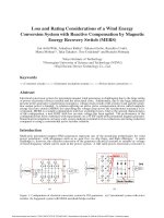
The EGR
system consists
of
piping arrangement taken from
the
engine exhaust pipe,
EGR
cooler with independent cooling circuit,
moisture trap and condensate drain
valve,
cartridge-type soot pre-
cipitator, and control valve;
to
change the amount
of EGR
intro-
duced
to
the cylinder. Schematic diagram
of EGR
system is
shown
in Fig.
2
.
The
temperatures
of
exhaust
gas,
cooled
EGR,
inlet
air,
and en-
gine
cooling water
are
measured using type-K
thermocoupl
es.
A PCB
Piezotronics
,
model 112B10,
combustion pressure sensor
is
used
to
measure the pressure inside the engine cylinder.
A PCB
Piezotronics, model 443A01, dual mode charge amplifier
is
used
to
condition and amplify the signal from the engine combustion
sensor.
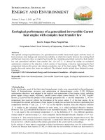
Fig. 1.
Schematic diagram
of
the test bed.
To
intake
charge
mixer
Soot
filter
fuel, and air;
respective
ly.
For
the dual-fuel with
EGR
operating mode, three ratios
of EGR
have been examined:
5%, 10%
and
20%. The
percentage
of
exhaust
gas
recirculation employed
(%EGR)
is
defined
on
mass basis
as
the
percent
of
the total intake mixture that
is
recycled exhaust
[27]
:
m
EGR
Shell-
and-tube
Co
oli
ng
wa
ter
ou
t
%E
GR
¼
i
100
ð
2
Þ
heat
exchang
er
From
exhaust
muffler
C
o
ol
in
g
w
at
er
in
where (m
EGR
)
is the
mass
of the
exhaust
gas
recycled,
and (m
i
) is
the
mass
of the
total intake:
(m
i
=
m
air
+
m
fuel
+
m
EGR
).
The
net heat release rate
(HRR) can be
calculated
by
the tradi-
tional first
law
equation
[27]
:
dQ
net
c
p
dV
1
dp
V
3
d
h
¼
c
1
d
h
þ
c
1
dh
ð Þ
Co
nd
en
sat
e
dra
in
Fig. 2.
Schematic
diagram
of EGR
system.
An
inductive magnetic
pickup sensor having
a one
degree reso-
lution
is
used
to
indicate
top
dead center
(TDC)
position and regu-
lar
intervals
of
crank angular
position
as well. A
wave
shaper is
used
to
manipulate
the sinusoidal wave,
produced
by
the sensor,
to
display the crank shaft
angular location.
A
Tektronix, model
TDS
430A,
two-channel
,
high-
speed
(400
MHz),
digitizing
,
real-time oscilloscope,
is
used
to
present, analyze, and
record the output signals
from the amplifier and
the
shaper.
A
pressure/crank
angle diagram
was
continuously dis-
played
on
the screen
of
the oscilloscope
while the engine
is
run-
ning,
thus enabling the effect
of a
change
in
conditions to be
observed immediately.
The
oscilloscope
is
outfitted
with an
eight-bit analog-to-
digital
(A/D)
converter
for
each channel,
to
al-
low
presenting,
analyzing
,
and
recording
of
high-speed
phenom-
ena. The
stored data
is
then retrieved and
transferred
to a PC
for
further
computation.
An ADC
multi-gas analyzer,
model
MGA3000,
is
used
for
mea-
suring exhaust
gas
concentrations from the
engine during operat-
ing
conditions. Typically,
NO, CO
and
CO
2
emissions
are
measured
using single-beam
non-dispersive infrared
(NDIR)
technology, while O
2
concentration
is
measured
using paramagnetic
cell
tech-
nology.
A CAI
flame ionization
detector,
600
series,
is
used
to
mea-
sure the
HC
emissions.
2
.
2
.
T
e
s
t
c
o
n
d
i
t
i
M.M.
Abdelaal,
A.H.
Hegab
/
Energy Conversion and Management
64
(2012) 301–
5
m
o
n
s
Th
e
expe
rime
ntal
tests
have
been
cond
ucte
d at
const
ant
engi
ne
spee
d
of
1600
rpm
for a
wide
rang
e
of
engi
ne
load;
rangi
ng
from
43%
up to
95%
of
the
engi
ne
full
load
at
this
spee
d.
At
each
load
point
,
three
oper
ating
mod
es
have
been
studi
ed:
conv
entio
nal
die-
sel,
plain
dual-
fuel
(with
out
EGR),
and
dual-
fuel
with
varia
ble
amo
unts
of
EGR.
Fo
r
both
plain
dual-
fuel
oper
ation
and
dual-
fuel
with
EGR,
the
pilot
amo
unt
of
the
liqui
d
diese
l
fuel
is
kept
const
ant
at
20%
of
the
rated
value
unde
r
conv
entio
nal
diese
l
oper
ating
mod
e,
whil
e
the
pow
er
outp
ut
of
the
engi
ne
is
adjus
ted
throu
g
h
c
o
n
t
r
o
l
l
i
n
g
t
h
e
a
m
o
u
n
t
o
f
t
h
e
g
a
s
e
o
u
s
f
u
e
l.
T
h
e
t
o
t
a
l
e
q
u
i
v
a
l
e
n
c
e
r
a
t
i
o
(
i.
e
.
t
h
a
t
t
a
k
e
s
i
n
t
o
a
c
c
o
u
n
t
b
o
t
h
f
u
e
l
s
)
i
s
c
a
l
c
u
l
a
t
e
d
a
s
:
where
(h) is the
crank angle
(CA), (p) is the
in-cylinder
pressure
at
a
given crank
angle,
(V) is the
cylinder
volume
at
that point,
and (c)
i
s
the
specific heat ratio
(
C
p
/
C
v
).
The
value
of (c)
varies with
the
vari-
ation
of the gas
temperature inside
the
cylinder
,
and
therefore
it
is
calculated
from a
polynomial
function
of bulk gas
temperature; see
Appendix
A
(and,
for
more details,
Ref.
[28]). The net HRR
repre-
sents
the
rate
of
energy release
from the
combustion processes
less
wall
heat transfer
and
crevice
flow
losses.
If the
crevice
flow
losses
are
disregarded,
the net HRR
represents
the
combustion
energy
re-
lease
less the
heat
loss to the
cylinder walls;
as
represented
by
Eq.
(3)
[27–29].
This
type
of
heat release model
is
referred
to in the
lit-
erature
as
zero-dimensional model.
For
each operating point
examined,
five
consecutive
pressure–
CAD
diagrams have
been recorded.
The
arithmetic
average
of
these
five
curves
has
been taken
to
represent
the final
pressure–CAD
dia-
gram; which
is
used
to
calculate the net
HRR. The
net
HRR
curve is
smoothed
by
arithmetic averaging
of
groups
of
every
five
consecu-
tive
points
on
the curve. More
details about the
methodology of
determining
the experimental
HRR can be
found
in
another work
of
the
author
[30]
.
For all
experiments
,
the
inlet
air
temperature
is 25 C,
the en-
gine
cooling
temperature
is
kept at
70
C ± 3 C,
and the
EGR
tem-
perature
,
when being
employed,
is
kept at
35 C.
The
tests have been
conducted
in
accordance
with
ISO
stan-
dards.
NO
emission concentration
is
corrected
for
ambient humid-
ity
and temperature
according to calculations
presented
in ISO
8
1
7
8
-
1
S
e
c
t
i
o
n
1
3
.
3.
Accuracy
of
measurements and
uncertainty analysis
To
ascertain the accuracy
of
measurements,
all
the
instruments
used
are
tested
and calibrated, under the
same operating condi- tions
of
the actual tests, before
conducting the experiments
.
Spe-
cial
emphasis
is
given
to
the exhaust
gas
emission
s
measurements.
All
gas
analyzers
are
purged after
each measure-
ment, and then
calibrated before the next
measurement using ref-
erence gases from
a
certified
source.
To
examine the
repeatability
of
measured
values, the experi-
ments
have been conducted such
that
five
measurements
of
each
parameter have been
recorded;
for
each operating
point.
The
val-
ues
reported
for all
measured parameters,
which
are
then used
for
further computations,
are
the
arithmetic mean ones
of
the
five measurements.
The
coefficient
of
variance
(COV)
for
each mea-
sured value
is
computed
,
to estimate the
repeatability
of
measure
-
A
F
R
sto
ic
m
_
N
G
AF
R
st
oic
m
_
ment and the
accuracy
of
procedure.
It has
been found that
the
/
tot
¼
NG
þ
D
1
Þ
air
where
(AFR
stoic
) and (AFR
stoic
)
are the
stoichiometric air–fuel
ratios
value
of COV of
each main
measured parameter
is less
than
0.5%.
Accordingly,
the
measurements precision
is
quite high.
To
estimate the limiting
error associated with each
measured
NG
D
6
M.M.
Abdelaal,
A.H.
Hegab
/
Energy Conversion and Management
64
(2012) 301–
(
m
_
NG
),
(
m
_
D
), and
(
m
_
air
) are the
mass
flow
rates
of
natural
gas,
Exhau
m
_
(mass
basis)
for
natur
al
gas
and
diesel
fuel;
respe
ctivel
y,
and
param
eter,
compr
ehensi
ve
uncert
ainty
analys
is
is
condu
cted;
M.M.
Abdelaal,
A.H.
Hegab
/
Energy Conversion and Management
64
(2012) 301–
7
Table 3
Absolute error and uncertainty
of
measured parameters.
Measured parameter Absolute error Uncertainty
(%)
Inlet air flow rate 0.357 m
3
/h 2.05
Diesel fuel flow rate 8.27 10
3
kg/h 2.7
Natural gas flow rate 1.284 10
2
m
3
/h 2.06
Engine speed 0.25 rev/s 1
Engine torque
0.6 N
m 2
EGR
temperature 0.55
C
1.57
NO
emission 2 ppm 2.35
CO
emission 0.002% 2.5
CO
2
emission
0.15%
3.57
O
2
emission 0.025% 0.69
HC
emission 3 ppm 3.06
70
Motoring
Diesel
60
D+CNG (0% EGR)
D+CNG+5%EGR
50
D+CNG+10%EGR
D+CNG+20%EGR
40
30
20
10
0
based
on
the accuracy
of
the instrument used and the measured
value
[31]. Table 3
summarizes the uncertainty analysis
of
the
measured parameters
in
the present study.
4.
Results and discussion
To
visualize the various effects
of
the utilization
of EGR in
pilot
ignited natural
gas
diesel engines, comparative results
are
given in
the following subsections
for
different operating modes: diesel,
plain dual-fuel (without
EGR),
and dual-fuel with variable
amounts
of EGR.
With regard
to
the in-cylinder pressure and heat release
rate, the experiments have been conducted
for only
two loads,
equivalent
to 52%
and
87% of
the engine
full load
at the operating
speed, and comparative results
are
given
for
different operating
modes. With regard
to
engine performance and emissions, the
experiments have been conducted
for all
cases examined
as
men-
tioned
in
section
2.2,
and the results
for
different operating modes
are
analyzed and presented graphically
for
brake thermal effi-
ciency, total equivalence ratio,
NO, HC, CO,
and
CO
2
emissions,
and O
2
concentration.
4.1. Cylinder
pressure
and heat
release
rate
4.1.1.
In-cylinder pressure
and
ignition delay
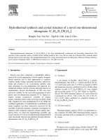
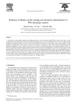
Figs. 3
and
4
show the pressure–crank angle degree
(CAD)
dia-
gram
for
both conventional diesel and plain dual-fuel modes at
52%
and
87% of
the engine rated
load
at the operating speed;
respec-
tively, and the motoring pressure
as well. It can be
seen
that at
all
loads, conventional diesel mode exhibits higher in-
cylinder
pressure and earlier start
of
combustion than dual-fuel
mode. This
is
attributed
to
the nature
of
the combustion process
in
each mode.
70
Motoring
Diesel
60
D+CNG (0%
EGR)
D+CNG+5%EGR
50
D+CNG+10%EGR
D+CNG+20%EGR
40
30
20
270 300 330 360 390 420 450
CAD (degree)
Fig. 4.
Pressure–crank
CAD
diagram
for
different operating modes at
87% of
the
engine rated load.
Conventional diesel mode
is
characterized
by a
heterogeneous
mixture, where the engine charge
is only air
while the diesel fuel
is
directly injected into the cylinder near the end
of
the compres-
sion
stroke. Broadly, the heterogeneous mixture undergoes a
non-premixed combustion process; except
for
the initial stage
where
a
rapid combustion
of
some
fuel
that
has
mixed with air
within the flammability limits during the delay period takes place
rapidly
in a few
crank angle degrees
[27].
It
is well
known
that the
non-premixed flames
are not
sensitive
to
the air–fuel ratio
(AFR)
value;
as
the combustion domain contains
a
variety
of
air–fuel
ra-
tios.
Therefore, the flame
is
well-anchored depending
on
the value
of
the
local AFR;
irrespective
of
the value
of
the overall
AFR,
which
can
reach
a
value
of 100 kg
air/kg
fuel. The
anchored flame and
the
associated high combustion efficiency result
in a
high peak
of
in-
cylinder pressure
[27]
.
On
the other hand, dual-fuel mode
is
characterized
by
non-pre-
mixed combustion
of
pilot diesel
fuel,
followed
by
premixed com-
bustion
of
the main gaseous fuel;
as
the charge
is a
homogenous
mixture
of
natural
gas
and
air
that
is
ignited
by
the injection of
the pilot diesel near the end
of
the compression stroke.
The
in-cyl-
inder conditions at that moment causes the pilot diesel
fuel
that
has
high cetane number
to
spontaneously ignite, providing
an
igni-
tion source
for
the subsequent flame propagation within the sur-
rounding gaseous fuel–air mixture.
That is,
there
are
two distinct
flames, resulted from the combustion
of
two different fuels; each
has its
own properties [5,15]. Unlike
non-premixed flame, pre-
mixed flame
is very
sensitive
to AFR. In
other words, the combus-
tion efficiency
for
premixed flames
is
the best when the
AFR
is
around the stoichiometric
condition
,
and deteriorates
as AFR
moves away from that condition. Observing the values
of AFR
in
Table 4,
which
are
calculated from the
flow
rates
of
intake
air,
die-
sel fuel,
and natural
gas
at the specified conditions,
it is
clear
that
the premixed combustion
in
dual-fuel mode suffers from
very
lean
mixture, which
is
reflected negatively
on
combustion efficiency,
and,
consequently, results
in
lower peak value
of
the in-cylinder
pressure
.
Table 4
Air–fuel ratio
(AFR)
values at different operating
conditi
ons.
10
Engine
load
(%
rated load)
0
Operating
mode
AFR
Diesel
(kg
air/kg
diesel)
AFR
Natural
gas
(kg
air/kg
natural gas)
Peak value
of
in-cylinder
pressure (bar)
270 300 330 360 390 420 450
CAD (degree)
Fig. 3.
Pressure–CAD diagram
for
different operating modes at
52% of
the engine
rated load.
52 Diesel 31 – 60.8
Dual-fuel 87.5 48 54.1
87 Diesel 22.5 – 69.5
Dual-fuel 85.5 36 63.3
P
r
e
s
s
u
P
r
e
s
s
u
28
26
24
22
20
Diesel
18
D+CNG (0% EGR)
16
D+CNG+5%EGR
14
12
D+CNG+10%EGR
10
D+CNG+20%EGR
8
6
4
2
0
Fig. 5.
Duration
of
ignition delay
(CAD) for
different operating modes at
52% of
the
engine rated load.
the ignition delay results from the chemical interactions between
the diesel vapor and the gaseous
fuel. This
chemical effect
has
been
examined
[32] on
the basis
of
adiabatic reaction conditions
a
t
mean temperature and pressure values similar
to
those during
the delay period
in
diesel engines, while employing detailed reac-
tion kinetics
for
the oxidation
of
dual-fuel
air
mixture.
It has
been
shown that the type
of
gaseous
fuel
and
its
concentration
in
the
cylinder charge considerably affect the ignition delay period, while
the physical properties
of
the mixture
is
maintained.
In fact,
the
changes
in
the ignition delay period
of
dual-fuel engine show
that
the extension
of
the chemical process
of
the ignition delay
with
the
admission
of
the gaseous
fuel is
the main rate-controlling
process during the delay period
of
dual-fuel engine
[32]
.
The
application
of EGR to
dual-fuel mode additionally increases
the ignition delay.
The
effect
is
enlarged
as EGR
percentage
is
in-
creased.
This is
because the application
of EGR
involves the
replacement
of
some
of
the intake
air
with combustion products.
That is,
the mixture
is
diluted and
its
heat capacity
is
increased,
3
0
2
8
2
6
2
2
2
0
1
8.
7
1
8
1
6
1
4
1
2
1
0
8
6
4
2
0
2
4
.
2
25.6
26.1
2
7
Die
sel
D+
CN
G
(0%
EG
R)
D+
CN
G+5
%E
GR
D+
CN
G+1
0%
EG
R
D+
CN
G+2
0%
EG
R
bon
dioxide and water vapor.
This will
partially obstruct
the com- bustion initiation
and
will
absorb some
of
the
heat relapsed
by
the
combustion
of
the pilot
fuel
as well. As a
result, ignition
delay is increased.
4
.
1
.
2
.
H
e
a
t
r
e
l
e
a
s
e
r
a
t
e
(
H
R
R
)
Figs. 7
and
8
show the
net
HRR
(Joule/CAD)
for
both
conven-
tional diesel and
plain dual-fuel modes at
52%
and
87% of
the en-
gine
rated
load
at the operating
speed; respectively.
For
both
cases,
it can be
seen
that the start
of
combustion
in
conventional
diesel mode
takes place earlier than that
of
dual-fuel mode;
as
re-
vealed
by
the sudden
rise in
HRR
at
an
earlier position.
27.5
26.1
26.3
23.7
I
g
n
i
t
i
o
n
M.M.
Abdelaal,
A.H.
Hegab
/
Energy Conversion and Management
64
(2012) 301–
9
This is
be-
cause
conve
ntional
d
i
e
s
e
l
m
od
e
ex
h
i
A
t
g
i
n
e
p
art load;
i.e. 52% of
the
engine rated
load, Fig.
7
shows that the trend
of
HRR
curves
of
both plain
dual-fuel (no
Fig. 6.
Duration
of
ignition delay
(CAD) for
different operating modes
at
87% of
the
engine rated load.
In
addition, the late start
of
combustion;
i.e.
the longer
delay
period,
of
dual-fuel
mode causes the whole
combustion process
to be
shifted further into the
expansion stroke.
Accordingly,
the
pressure
rise
is
moderated
as
the piston
moves
in
the expansion
stroke down away from the
top
dead center
(TDC);
increasing
the volume and
reducing the peak pressure.
The
application
of EGR to
dual-fuel mode decreases the
cylinder pressure.
The
effect
is
more obvious with high
EGR
percentages of
20%,
where larger amount
of
O
2
is
replaced
by
CO
2
and
H
2
O.
This
suppresses the
combustion process and
damps the pressure rise.
Consequently, the peak
pressure becomes lower.
EGR)
and dual-fuel with
EGR
is
analogous
to
that
of
conventional
diesel.
That is,
the
HRR
curve
is
characterized
by
the presence
of
two peaks; the first peak
is for
the premixed rapid
combustion
phase and the
other
one is for
the mixing-
controlled combustion
phase.
This is
because at
low
loads,
a
small amount
of
natural
gas is
being utilized, and
as
the diesel pilot amount
is
quantifie
d
as a
percentage
of
its
rated value at conventional
diesel operation,
the pilot
diesel
fuel
quantity
in
this
case
represents
a
considerable
portion
of
the total
fuel
mass
introduced
to
the cylinder.
Therefore,
the traditional
HRR
curve pattern
of
conventional diesel
dominate
s.
70
Diesel
The
ignition delay period
is
defined
as
the period
between the
60
start
of fuel
injection into
the combustion chamber
and
the start
of
combustion, identified
by
the change
in
the slope
of
the
p–h dia-
50
gram
[27]. In
the present
work, the start
of
combustion
is
identified
40
as
the point at which the
firing diagram separates
from the motor-
ing
diagram.
Figs. 5
and
6
show the duration
of
ignition delay,
ex-
30
pressed
in
degrees,
for
different operating modes
at
52%
and
87%
of
the engine rated
load
at
the operating speed;
respectively. Dual-
20
fuel
mode demonstrates
longer delay period than
conventional
10
d
i
e
s
e
l
m
o
d
e
.
T
h
i
s
i
s
b
e
c
a
u
s
e
t
h
e
i
n
t
r
o
duction
of
gaseous fuels
to
the intake
air of a
diesel
engine increases both the
physical and
0
D
+
chemical processes
of
the
ignition delay period.
The
extension of
the physical
process
of
the delay period
results from the decrease
in
the charge temperature, the
decrease
in
the partial
pressure of
oxygen, and from
the absorption
of
some
of
the
pre-ignition energy release;
as
the gaseous fuel–air mixture
has a
higher specific
heat
330 340 350
360 370
380 390
400
-10
C
A
D
(
d
e
g
r
e
e
)
Fig. 7.
Net
HRR
(Joule/CAD)
for
different operating modes at
52% of
the engine
rated
load.
1
M.M.
Abdelaal,
A.H.
Hegab
/
Energy Conversion and Management
64
(2012) 301–
capacity than the pure
air. The
extension
of
the chemical process
3
N
e
t
H
R
R
70
Diesel
60
D+CNG (0%
EGR)
D+CNG+5%EGR
50
D+CNG+10%EGR
D+CNG+20%EGR
40
30
20
10
0
330 340 350 360 370 380 390 400
-10
CAD (degree)
Fig. 8.
Net
HRR
(Joule/CAD)
for
different operating modes at
87% of
the engine
rated
load.
It can also be
noted form
Fig. 7
that dual-fuel mode exhibits
lower values
of HRR,
compared with conventional diesel mode.
This is
because
of
the
very
lean mixture
of
gaseous-fuel and air
at part
load,
and the associated poor
fuel
utilization efficiency. In
such
a case,
large portion
of
natural
gas
escapes from the combus-
tion process,
as
revealed
by
the
low HRR. A
slow burning rate of
natural
gas is also
observed.
The
presence
of EGR
absorbs
a
consid-
erable amount
of
the heat release,
as a
result
of
substituting some
of
O
2
by
CO
2
and part
of
H
2
O
in
the exhaust
gas. This
increases
the
charge heat capacity and dilutes the mixture [33,34]. It
also
sup-
presses the burning rate
of
natural
gas [35]. As a
result,
a
further
reduction
in
heat release
is
observed when
EGR is
employed; com-
pared with plain dual-fuel with
no EGR.
4.1.3. Rate of
pressure
rise (ROPR)
The
pressure–time data
is
used
to
calculate the rate
of
pressure
rise, or
the slope
of
the pressure–CAD curve, at each data point. To
obtain
ROPR
curve, the actual pressure–CAD curve
is
divided into
several segments, and the equation
of
each segment
is
obtained
as p = f(h). The
differentiation
of
each equation with respect to
the independent variable
(h) gives
the rate
of
pressure
rise
(
dp
/
dh)
at the certain segment. Complete
ROPR
curve
is
then con-
structed.
A
typical
ROPR
curve against
CAD for a
given pressure–
CAD
curve
is
shown
in Fig. 9.
It
can be
seen that the
ROPR
increases
during compression and early stages
of
combustion until
it
reaches
its
highest value at
a
certain
CAD
then starts
to
decrease
,
while
the
pressure
is still
increasing
till
the peak pressure point.
The
maxi-
mum value
of
the
ROPR
data
is
then taken and recorded,
in
units
of bar/CAD, to
represent the combustion noise at the
correspond
-
ing
conditions.
Figs. 10
and
11
show the maximum
ROPR
that may represent
combustion noise,
for
different operating modes, at
52%
and
87%
of
the engine rated
load
at the operating speed; respectively.
I
t
can be
seen that there
is
evident coincidence
between the combus-
tion noise and the maximum
HRR.
Conventional diesel mode in-
volves
an
intense combustion
of
large amount
of
diesel
fuel
that
releases
a
large amount
of
heat,
as
demonstrated
by
high peak of
HRR,
associated with rapid pressure
rise
rates. Consequently,
the
combustion noise
of
conventional diesel mode
is
always higher
than that
of
dual-fuel mode.
80
ROPR
In
contrast, at engine high load;
i.e. 87% of
the engine rated
load,
6
a
large amount
of
natural
gas is
being used
in
dual-fuel mode,
while the pilot amount
is
kept constant. Increased mixture
4
strength leads
to an
improvement
in fuel
utilization efficiency; as
the premixed natural gas–air mixture becomes closer
to
the
correct
mixture conditions, and the burning rate
of
the natural
gas be-
2
comes
very fast
and the combustion duration becomes shorter
[35].
Consequently, the major portion
of
the combustion process
0
is in
the rapid burning phase;
as
illustrated
by Fig. 8,
where the
HRR
curve
of
dual-fuel mode
is
characterized
by
the presence of
only one
peak
for
the rapid combustion phase. However, after
-2
reaching the peak value
of HRR,
the curve
falls
down with
a
slower
rate than that
of its
rise; because
of
the mixing-controlled
combus-
tion
of
the pilot diesel residue that releases some heat
and hence
Pressure
60
40
20
0
CAD (degree)
causes the
HRR
curve
to
diverse somehow and
not to fall
sharply.
Nevertheless, the peak
of HRR in
conventional diesel
mode remains
higher than that
of
dual-fuel mode.
This is
because conventional
diesel mode utilizes
a
large amount
of fuel
at high loads; which
re-
sults
in a
higher in-cylinder temperature, and hence, higher
rates
of fuel
evaporation and mixing. Consequently,
a
larger
portion of
the premixed mixture
in
the preparation zone
is
formed.
The
pre-
mixed rapid combustion
of
this large amount
of
diesel
fuel
releases large amount
of
energy, and hence results
in a
higher peak value of
Fig. 9.
Typical
ROPR
curve against
CAD for
a given pressure data.
5
4.5
4
3.5
Diesel
HRR.
At
engine high
load, in
addition, the
EGR
contains
a
sufficient
amount
of
active radicals and unburned
fuel
molecules.
The
active
radicals
are
expected
to
improve the combustion process [36,37]
while the unburned
fuel
molecules
are
expected
to
reburn
in
the
mixture [38,39].
The
combination
of
these two effects causes
the
HRR to
increase, compared with the
plain dual-fuel mode, particu-
larly
with high
EGR
percentages
of 10%
and
20%. At a low EGR
per-
centage
of
5%,
however, the effect
of
the presence
of
active radicals
and unburned hydrocarbon
is
moderated
by
the dilution effect of
3
2.5
2
1.5
1
0.5
0
D+CNG (0% EGR)
D+CNG+5%EGR
D+CNG+10%EGR
D+CNG+20%EGR
N
e
t
H
R
R
R
O
P
R
-
d
P
/
d
θ
P
r
e
s
s
u
3.25
2.86
M
a
x
.
R
a
t
e
o
f
P
r
e
s
EGR
and
by
the increase
in
the mixture heat capacity.
HRR
there-
fore
remains almost unchanged with
low EGR
ratios.
Fig. 10.
Maximum
ROPR
(representing combustion noise)
for
different operating
modes at
52% of
the engine rated load.
Concerning the application
of EGR to
dual-fuel mode,
it
has
been found that
a low EGR
percentage
of 5%
causes
a
reduction
in
the combustion noise; at
all
engine loads.
This is
attributed to
the reduced oxygen concentration
of
the mixture (dilution effect
of EGR),
and
to
the increase
in
the mixture heat capacity (thermal
effect
of EGR).
With higher
EGR
percentages
of 10%
and
20%,
how-
ever,
the effect
of
the presence
of
active radicals and unburned
hydrocarbons (radical effect
of EGR)
improves the combustion con-
ditions,
as
revealed
by a
relatively higher peak
of HRR,
and conse-
quently,
it
generates
a
higher combustion noise, but
its
value
continues
to be
inferior than that
of
the plain dual-fuel mode
at
part loads;
as
shown
in Fig. 10.
A
t
high loads, however, the radical
effect
of EGR
becomes considerable,
as EGR in
such conditions con-
tains sufficient amount
of
active radicals and unburned
fuel
mole-
cules.
This is
demonstrated
by
considerably higher peak
of HRR
for
the
EGR
ratios
of 10%
and
20%,
and the combustion noise
in
such
cases exceeds that
of
plain dual-fuel;
as
shown
in Fig. 11.
However
,
it can be
seen that the maximum
ROPR
(representing combustion
noise) with
20% EGR is
lower than that with
10% EGR,
although
the former contains lager amount
of
active radicals and unburned
hydrocarbons.
This is
attributed
to
the substantial reduction in
oxygen concentration
in
the cylinder with high
EGR
ratios at high
loads,
as
the reduced oxygen concentration adversely affect
the
combustion process and the possibility
of
reburning the
unburned
hydrocarbon.
As a
result,
20% EGR
exhibits lower peak
of
HRR
and,
consequently, lower combustion noise than
10% EGR.
4.2. Engine
performance analysis
4.2.1. Brake
thermal efficiency
Fig. 12
shows the brake thermal efficiency trends
for
different
operating modes, throughout
a
wide range
of
engine loads; from
43% up to 95% of
the engine
full load
at the operating speed. It
can be
seen that the dual-fuel engine suffers from lower brake
thermal efficiency at part loads,
in
comparison with
conventional
diesel mode.
This is
because
of
the
very
lean mixture
of
gaseous
fuel
and
air
at part
load
and the associated poor
fuel
utilization
effi-
ciency.
That is, in
this
case, only
the part
of
gaseous fuel–air
mix-
ture that
is very
close
to
the diesel preparation zone
is
entrained
in
such
a
zone that subsequently burns; while the rest
of
the gas-
eous
fuel
escapes from the combustion process, since
it
forms a
very
lean mixture with
air
that cannot
be
burned, and
goes
with the exhaust.
At
high loads,
on
the contrary,
a
larger
amount
of
gas-
eous
fuel is
being introduced
to
the cylinder, while
the pilot diesel
quantity
is
kept constant. Consequently, the
mixture strength
is
in-
creased; leading
to an
improvement
in fuel
utilization,
as
the gas-
5
eous fuel–air mixture becomes
able to
form
a
sustainable flame,
and hence,
a
larger amount
of
the gaseous
fuel is
involved
in
the
combustion process.
In
addition, the
very fast
burning rate
of
the
natural
gas
causes
a
larger portion
of
the combustion process to
take place closer
to
the
TDC; i.e.
at the beginning
of
the power
stroke.
This
results
in
producing more power from the dual-fuel
combustion at high
load
conditions, compared with
diesel combus-
tion at the same conditions,
as
the latter
is
characterized
by a
long-
er
combustion duration where
a
considerable portion
of
the
combustion takes place
in
late stages
of
the power stroke; reducing
the useful power obtained. Moreover, the high peak
of HRR
associ-
ated with the diesel combustion increases the radiative heat
loss
to
the cylinder walls and
to
the formed exhaust, due
to
the high
emis-
sivity rate, and this
also
adversely affects the brake
thermal
efficiency.
Concerning the application
of EGR to
dual-fuel mode,
Fig.
12
shows that the utilization
of a low
percentage
of EGR of 5%
causes
almost
no
change
in
the brake thermal efficiency at
low
loads. At
medium loads,
a
slight improvement
in
the thermal efficiency is
obtained with
5% EGR. This
may
be
attributed
to
the reburning of
some
of
the hydrocarbons that
is
contained
in
the
EGR. At
high
loads,
however
,
slight decrease
of
the brake thermal efficiency is
observed
,
due
to
the reduced oxygen concentration that adversely
affect the combustion process. With high percentages
of EGR
of
10%
and
20%, a
considerable improvement
in
the brake thermal
efficiency
is
observed; at part and medium loads.
This is
because
a
larger amount
of
active radicals and unburned hydrocarbons is
admitted into the cylinder when high percentages
of EGR are
used.
Also,
the partly-cooled
EGR acts like a
pre-heater
for
the intake
charge; improving the combustion conditions. These effects are
more prudent at high percentages
of EGR.
Therefore,
20% EGR
exhibits
a
higher brake thermal efficiency
at these operating condi-
tions.
At
high loads, however, the amount
of fuel
supplied
to
the
cylinder
is
increased at
a
higher rate, and the oxygen available
for
combustion gets reduced
substantially
.
The
presence
of EGR
further aggravates the problem and the combustion process is
deteriorated
.
The
brake thermal efficiency
is
therefore reduced.
Moreover, the increased
CO
2
concentration with high the
EGR
per-
centages increases the heat capacity
of
the mixture and absorbs
more heat.
Again,
the effects become more voluminous
as EGR
per-
centage
is
increased, and therefore
20% EGR
exhibits
a
lower effi-
ciency at high loads.
4.2.2.
Equivalence
ratio
(
/
)
The
preference
of
using the equivalence ratio
(
/
)
to present the
results
of
the current study rather than the
use of air to fuel
ratio
(AFR) is
due
to
the
fact
that every particular
fuel has its
distinctive
4.5
4
3.5
3
2.5
2
1.5
1
0.5
0
4.39
3.25
3.03
4.04
3.51
Diesel
D+CNG (0% EGR)
D+CNG+5%EGR
D+CNG+10%EGR
33
31
D+CNG (0%
EGR)
D+CNG+5%
EGR
D+CNG+10%
EGR
29
D+CNG+20%
EGR
25
23
21
19
40 50 60 70 80 90 100
% Engine Full-load
Fig. 11.
Maximum
ROPR
(representing combustion noise)
for
different operating
modes at
87% of
the engine rated load.
Fig. 12.
Brake thermal efficiency trends
for
different operating modes.
M.M.
Abdelaal,
A.H.
Hegab
/
Energy Conversion and Management
64
(2012) 301–
1
M
a
x
.
R
a
t
e
o
f
P
r
e
s
B
r
a
k
e
T
h
e
r
m
a
stoichiometric
air to fuel
ratio (AFR
stoic
); that differs from those of
other fuels.
The
present work involves
dual-fuel experiments, and
therefore the
use of
the equivalence ratio
to
represent the results
has
the merit
of
taking into account the variation
of
AFR
stoic
form
diesel
fuel to
natural
gas;
while the
use of AFR
does not;
as it
only
considers the masses
of air
and fuels.
Fig. 13
shows the equivalence ratio
(
/
)
for
different operating
modes; estimated from stoichiometric combustion equations and
from actual
flow
rates
of air
and fuels.
It can be
noted that the con-
ventional diesel operation exhibits lower equivalence ratio
than
that
of
the plain dual-fuel operation; at
low
and medium
load
con-
ditions.
This is
because the diesel combustion process involves
the
utilization
of a
large amount
of
excess
air,
due
to
the heteroge-
neous mixture.
That is; a
leaner mixture
is
required.
At
high load
conditions,
on
the other hand, the plain dual-fuel mode demon-
strates
a
lower equivalence ratio than conventional diesel mode.
This is
because dual-fuel mode at such conditions
has
lower spe-
cific fuel
consumption,
as
revealed
by
the higher thermal effi-
0.9
0.8
0.7
0.6
0.5
0.4
Diesel
D+CNG (0%
EGR)
D+CNG+5%
EGR
D+CNG+10% EGR
D+CNG+20% EGR
40 50 60 70 80 90 100
% Engine Full-load
Fig. 13.
Equivalence ratio
(
/
)
for
different operating modes.
ciency. Although the dual-fuel operation involves reduction in
the amount
of air
introduced
to
the cylinder
as a
consequence of
the utilization
of
the gaseous
fuel,
the reduction
in
the total
amount
of fuel
used
is
larger.
As a
result, the equivalence
ratio be-
comes inferior.
The
application
of EGR to
dual-fuel mode affects the equiva-
lence ratio
in
two different manners; depending
on
the
load
condi-
tions.
At low
and intermediate loads, the effect
of
the reduction in
fuel
consumption
as a
result
of
the presence
of
active radicals and
reburning
of
unburned hydrocarbons predominates
.
Therefore,
the
equivalence ratio
is
lower than that associated with the plain dual-
fuel. The
effect becomes more visible
as
the
EGR
percentage
is
in-
creased.
At
high loads,
in
contrast,
a
large amount
of
gaseous
fuel
is
used, and the combustion
air is
reduced.
The
application
of EGR
further worsens the situation;
as
it replaces
a
considerable
amount
of
the
air
available
for
combustion.
In
addition, the combustion
process deteriorates, and the specific
fuel
consumption increases.
As a
result, the equivalence ratio becomes higher than that associ-
ated with the plain dual-fuel.
Again;
the effects
are
more apparent
with high
EGR
percentages.
4.3. Exhaust
emission analysis
4.3.1. Nitric oxide
(NO)
The
formation
of
the nitric oxide
in
the combustion zone
is
due
to
two mechanisms; typically, the thermal mechanism (Zeldovich
mechanism) and the prompt mechanism (Fenimore
mechanism
).
The
thermal
NO
formation
is
established
by
high-tempe
rature
combustion;
i.e.
when the combustion temperature
goes
higher
than 1400
K. In
this
mechanism
,
the formation rate
of NO
increases
exponentially with the increase
in
the combustion
temperature
,
and
vice
versa.
On
the other hand, the prompt
NO
formation is
established within the
rich,
low-temperature combustion zones;
where
a
reasonable amount
of
active radicals
is
available
.
Fig. 14
shows the nitric oxide
(NO)
emission
for
different oper-
ating modes; expressed
as
emission index
(EI NO). It can be
clearly
noted that conventional diesel mode emits the largest amount of
nitric oxide.
This is
because the conventional diesel combustion
is
characterized
by
the formation
of a
preparation zone, which is
a
thin layer
of
nearly stoichiometric air–fuel mixture, surrounded
by a rich
mixture zone.
As
combustion starts, the flame
is
anchored
throughout the preparation zone at nearly stoichiometric condi-
tions; resulting
in
high-temperature combustion.
This is
responsi-
ble for
the formation
of
thermal
NO. In
turn, the combustion
of
the
surrounding
rich
mixture zone
is
responsible
for
prompt
NO
for-
mation.
To
sum
up,
due
to
the nature
of
diesel combustion,
a
large
amount
of NO is
formed according
to
two distinct formation mech-
anisms, although prompt
NO for
diesel engine
is very
small; com-
pared with thermal NO.
On
the other
side,
dual-fuel combustion
is
characterized
by
the
presence
of
two combustion configurations; typically, non-pre-
mixed combustion
of
the pilot diesel, and premixed combustion
of
the gaseous
fuel. The
non-premixed combustion
of
the pilot die-
sel
spray
is
responsible
for
the formation
of
some thermal and
prompt
NO,
but
in a
much smaller quantities than those associated
with the conventional diesel combustion,
as
the pilot diesel quan-
tity
is
considerably small. Besides, the premixed combustion
of
the
gaseous
fuel
produces
only
tiny amount
of NO,
because
of
the very
lean mixture that results
in
low-temperature combustion, while
there
are not any rich
zones; particularly at part
load. At
high load,
however
,
NO is
noticeably increased
in
dual-fuel mode,
as a
result
of
the increased mixture strength that results
in
enhanced com-
bustion at high
temperature
,
but
its
value remains inferior
to
that
of
diesel
combusti
on.
The
most appraised effect
of
the application
of EGR to
dual-fuel
engines
is its
significant contribution
to
the decrease
of
nitric oxide
emissions.
As
widely recognized, the formation
of
nitrogen oxides
is
favored
by
high oxygen concentration and high charge
tempera-
ture [26,27].
In
dual-fuel engines, the application
of EGR
highly di-
lutes the mixture and increases
its
heat capacity;
as a
part
of
O
2
is
replaced
by
CO
2
and some
H
2
O.
Consequently, the oxygen concen-
tration
is
reduced and the combustion temperature
is
lowered.
This
combined effect therefore suppresses
NO
formation.
The
high-
er
the percentage
of EGR is
employed, the larger the reduction of
NO is
achieved.
4.3.2.
Unburned hydrocarbon (HC)
Fig. 15
shows the unburned hydrocarbon
(HC)
emission
for
dif-
ferent operating modes; expressed
as
emission index
(EI HC).
As
conceded, the variation
of
the unburned hydrocarbon emission in
exhaust
gas is
consistent with the quality
of
the combustion pro-
cess
[26,27]. Observing
Fig. 15,
it
is
obvious that dual-fuel mode
suffers from significantly
a
higher
HC
emission
,
compared with
conventional diesel mode, particularly at part
load
conditions.
This
is
because
of
the
very
lean mixture
of
gaseous-fuel and
air
at
such
conditions and the associated poor
fuel
utilization efficiency,
since
a
large portion
of
the natural
gas
escapes from the
combustion pro-
cess; increasing the
HC
emissions.
At
high loads,
the increase
in
the
mixture strength and the improvement
in
the
fuel
utilization cause
a
dramatic reduction
in HC
emission, but
its
value continue
to
be
higher than that
of
conventional diesel mode.
The
application
of EGR to
dual-fuel mode reduces the
HC
emis-
sion
levels, particularly at part
load. This is
because with
EGR,
a
portion
of
the unburned hydrocarbon
is
recirculated and reburned
E
q
u
i
v
a
l
e
22
Diesel
D+CNG (0% EGR)
20
D+CNG+5% EGR
18
D+CNG+10% EGR
D+CNG+20% EGR
16
14
12
10
8
6
4
2
0
40 50 60 70 80 90 100
% Engine Full-load
150
135
120
105
90
75
60
45
30
15
0
Diesel
D+CNG (0%
EGR)
D+CNG+5%
EGR
D+CNG+10% EGR
D+CNG+20% EGR
40 50 60 70 80 90
100
% Engine
Full-load
Fig. 14.
Nitric oxide emission index
(EI NO) for
different operating modes.
in
the mixture; due
to
the presence
of a
sufficient amount
of
oxy-
gen in
the combustion chamber at part loads.
This
effect
is
more
evident with high percentages
of EGR, as
they contain
a
larger
amount
of
unburned hydrocarbon.
At
high loads,
however
,
the re-
duced oxygen concentration adversely affects the possibility of
reburning the unburned hydrocarbon; especially with high per-
centages
of EGR. That is,
the capability
of EGR to
reduce the
HC
emissions
via
the reburn
of
some
of
the unburned hydrocarbon is
contingent upon the excess oxygen availability
in
the combustion
chamber.
As a
consequence, the effect
of EGR in
reducing
HC
emis-
sion
from the dual-fuel engines at high loads
is
negligible.
4.3.3. Carbon
monoxide
(CO)
Fig. 16
shows the carbon monoxide
(CO)
emissions
for
different
operating modes; expressed
as
emission index
(EI CO). As
known,
the rate
of CO
formation
is a
function
of
the unburned gaseous fuel
availability and mixture
temperature
,
both
of
which control the
rate
of fuel
decomposition and oxidation [26,27]. Observing
Fig. 16,
it
can be
clearly noticed that
CO
emission with dual-fuel
mode
is
always higher than
its
counterpart with conventional die-
sel
mode.
This is
because dual-fuel mode suffers from
a
poor fuel
utilization that leads
to
incomplete combustion and high
HC
emis-
sion. That is,
the process
of fuel
decomposition and oxidation
is
not
optimized, and consequently,
CO
emission
is
increased.
As
the load
is
increased, the improvement
in
the combustion process reduces
CO
emission;
as
more
fuel
experiences
a
complete combustion.
The
utilization
of EGR in
dual-fuel engines contributes
to a
fur-
ther reduction
in CO
emissions,
as it
provides the opportunity to
reburn
a
part
of
the unburned hydrocarbon, increasing the possi-
bility
of
complete combustion.
Also,
the active radicals present in
EGR
improve the combustion conditions. Further,
as
the tempera-
ture
of
partly-cooled
EGR is
slightly higher than the atmospheric
temperature
,
the application
of EGR
involves
an
increase
in
the in-
take charge
temperature
,
contributing
to a
lower
CO
emission. To
sum
up,
the addition
of EGR
involves the reburn
of
some
of
the un-
burned hydrocarbon and slightly increases the charge tempera-
ture.
This
combined effect causes
a
reduction
in CO
emission. The
trend
is
almost the same
for
both
EGR
percentages
of 5%
and
10%;
and the effect
is
more apparent with the latter. Although
higher
EGR
percentage
of 20%
exhibits the same trend at part
loads,
it
demonstrates
a very
high
CO
emission at high loads,
as a
result of
a
massive reduction
in
oxygen concentration
of
the
charge and
the
associated
low AFR,
since
a
large amount
of EGR
is
introduced in
place
of
the intake air.
4.3.4. Carbon dioxide
(CO
2
)
Fig. 17
shows the carbon dioxide
(CO
2
)
emission
for
different
operating modes; expressed
as
emission index
(EI
CO
2
).
It can
be
Fig. 15.
Unburned hydrocarbon emission index
(EI HC) for
different operating
modes.
100
Diesel
90
D+CNG (0%
EGR)
80
D+CNG+5%
EGR
D+CNG+10%
EGR
70
D+CNG+20%
EGR
60
50
40
30
20
10
0
40 50 60 70 80 90 100
% Engine Full -load
Fig. 16.
Carbon monoxide emission index
(EI CO) for
different operating modes.
seen that dual-fuel mode emits considerably lower
CO
2
emission,
compared with conventional diesel mode.
This is
because
of
the
clean nature
of
combustion
of
the natural
gas,
due
to
the lower car-
bon-to-hydrogen ratio
(C/H); for one
reason.
The
other reason may
be
the high
HC
emission
of
dual-fuel mode and the incomplete
combustion,
as
revealed
by
the high
CO
emission; particularly
at
part loads.
At
high loads,
however
,
the improvement
in
the com-
bustion process causes
CO
2
emission
to
increase, but
its
value re-
mains inferior
to
that
of
diesel combustion.
The
application
of EGR to
dual-fuel mode increases
CO
2
emis-
sion
at part loads.
This is
attributed
to
the increased
CO
2
concen-
tration
in
the intake charge
as a
result
of
the application
of EGR.
In
addition, the improvement
in
the combustion process due to
the presence
of
active radicals and reburning
of
some unburned
hydrocarbon causes
CO
2
emission
to
increase; and the effect be-
comes stronger
as
the
EGR
percentage
is
increased.
At
high loads,
however
,
the reduced oxygen concentration
as
the
EGR is
em-
ployed adversely affects the combustion process, and therefore
CO
2
emission
is
reduced.
The
reduction
in
CO
2
at high loads is
noticeable with high
EGR
percentage
of 20%, as
the combustion
deteriorates at such conditions because
of
the considerable lack
of
oxygen.
4.3.5. Oxygen
(O
2
)
When
a
sufficient amount
of air is
used
to
burn
a
certain
amount
of fuel in a CI
engine, some
of
the oxygen content
of
the
air is
used
to
oxidize the
fuel,
while the excess oxygen
goes
with
the exhaust
as it is. In
addition, the part
of air
away from the com-
E
I
N
O
(
g
E
I
H
C
(
g
E
I
C
O
(
g
/
2700
2600
2500
2400
2300
2200
2100
2000
1900
1800
1700
Diesel
D+CNG (0% EGR)
D+CNG+5% EGR
D+CNG+10% EGR
D+CNG+20% EGR
40 50 60 70 80 90 100
% Engine Full -load
5.
Conclusions
The
present work aims at investigating the effect
of
utilization
of
partly-cooled
EGR on
the combustion process and exhaust emis-
sion
characteristics
of a
pilot ignited natural
gas
diesel engine.
A
comparative study between various engine operating modes; con-
ventional diesel mode, plain dual-fuel mode (without
EGR),
and
dual-fuel with variable amounts
of EGR;
typically
5%, 10%,
and
20%, has
been conducted at different running conditions.
The
prin-
cipal
findings from this study are:
(1) The
cylinder peak-pressure
of a
diesel engine
can be
reduced
by
applying the dual-fuel strategy.
The
utilization
of EGR
further reduces the peak pressure and hence extends the
engine
life. The
effect increases with the increase
of
the
EGR
percentage.
Fig. 17.
Carbon dioxide emission index
(EI
CO
2
)
for
different operating modes.
16
Diesel
14
D+CNG (0%
EGR)
D+CNG+5%
EGR
12
D+CNG+10%
EGR
D+CNG+20%
EGR
10
8
6
4
2
40 50 60 70 80 90 100
% Engine Full-load
Fig. 18.
Oxygen concentration
(%
O
2
)
for
different operating modes.
bustion zone does
not
experience the combustion process at all,
but
goes
with the exhaust
as it is. The
oxygen found
in
the exhaust
gas
comes from these two sources.
Fig. 18
shows the oxygen (O
2
) concentration
in
the exhaust gas
for
different operating modes.
For all
modes, the oxygen
concentra-
tion
in
the exhaust
gas
notably reduces with the increase
in
the
en-
gine load, as a
consequence
of
the utilization
of a
larger
amount of
fuel
that consumes
a
more amount
of
the oxygen
present
in
the
cylinder.
The
oxygen concentration
in
the exhaust
gas is a
direct
reflection
of
cylinder charge composition.
That is,
conventional die-
sel
mode exhibits the highest oxygen
concentration
in
the exhaust
gas,
since the intake charge
is only air.
Part of
the intake
air
oxygen
is
used
to
burn the diesel
fuel,
while
the excess oxygen exits
with
the exhaust
as it is. On
the other
side,
dual-fuel mode involves
the
replacement
of
some
of
intake
air by
the gaseous
fuel. As a
conse- quence, the oxygen content
of
the
charge
is
reduced, and therefore,
the oxygen concentration
in
the
exhaust
gas will be
reduced. How-
ever,
the amount
of
the
gaseous
fuel
that replaces the oxygen is
much smaller,
compared to the cylinder charge, and therefore
the oxygen
concentration
in
dual-fuel mode
is
comparable
to
that
in
conventional diesel mode.
The
utilization
of EGR in
dual-fuel engines involves
the replace-
(2)
Dual-fuel mode exhibits longer ignition delay than that of
conventional diesel mode.
The use of EGR
further extends
the delay period.
The
duration
of
the ignition delay period
can be
arranged
in an
ascending order
for
different operating
modes
as:
diesel, plain dual-fuel, dual-fuel with
5% EGR,
dual-fuel with
10% EGR
and dual-fuel with
20% EGR.
(3) The
value
of
the maximum rate
of
pressure
rise
with dual-
fuel
mode
is
lower than that with conventional diesel mode.
The
application
of EGR to
the dual-fuel mode causes
a
fur-
ther reduction
in
that value.
(4)
Dual-fuel mode suffers from
a
lower thermal efficiency
than
conventional diesel mode at part loads.
However
,
the
case
is
reversed at high loads; where dual-fuel mode demonstrates
a
higher efficiency.
The use of EGR
alters the thermal effi-
ciency
by
increasing
or
decreasing; depending
on
the load
conditions. Dual-fuel mode with
EGR, in
general, exhibits
thermal efficiency comparable
to
conventional diesel mode.
(5)
Dual-fuel strategy
is a very
promising solution
to
reduce
NOx
emissions from diesel engines. Moreover, the applica-
tion
of EGR to
dual-fuel mode causes
an
additional reduction
of NOx
emissions significantly.
The
higher the percentage of
EGR is
employed, the larger the reduction
of NOx
is
achieved.
(6) HC
and
CO
emissions
of
conventional diesel mode
are
lower
than those
of
dual-fuel mode; especially at engine part loads.
Nevertheless,
HC
and
CO
emissions
of
dual-fuel mode reduce
with the increase
of
the engine
load. The
application
of EGR
to
dual-fuel mode slightly reduces
HC
and
CO
emissions,
but
their values
are still
considerably higher than that
of
con-
ventional diesel mode.
(7)
CO
2
emission
of
dual-fuel mode
is
noticeably lower
than that
of
conventional diesel mode; at
all
loads.
The
application of
EGR to
dual-fuel mode increases
CO
2
emission, but
its
value
remains inferior
to
that
of
conventional diesel mode.
Appendix
A
The
value
of
the specific heat ratio
(c)
used
to
calculate
the net
heat release rate
(HRR)
varies with the variation
of
the
gas
temper-
ature inside the cylinder, and
it can be
calculated from the follow-
ing
equation
[28]
:
ment
of an
additional amount
of
the intake
air
with combustion
R
1
products.
That is,
the oxygen available
in
the cylinder
is
consider-
ably
reduced; especially with high
EGR
ratios at high loads. There-
c
¼
1
p
ð
4
Þ
fore,
the oxygen concentration
in
the exhaust
gas is
substanti
ally
reduced, and
it
principally comes from the
air
that escaped from
where
(R) is the gas
constant;
(J/kg k), and
(
C
p
)
is the
specific heat of
the gas at
constant pressure;
(J/kg k). The
value
of
R
can be
cal-
p
the combustion process.
culated from:
E
I
C
O
2
(
g
O
(
2
C
C
A
0
þ
A
1
T
þ
A
2
T
2
þ
A
3
T
3
þ
A
4
T
4
Þ
ð
5
Þ
[16] Mbarawa
M,
Milton
BE,
Casey
RT.
Experiments and modeling
of
natural gas
R
1
C
p
¼ ð
where
(
A
0
),
(
A
1
),
(
A
2
),
(
A
3
),
and
(
A
4
)
are
constants,
and
their values
are
[28]
:
A
0
¼
3
:
04473
A
1
¼
1:33805
10
3
A
2
¼
4:88256
10
7
A
3
¼
8:55475
10
11
A
4
¼
5:70132
10
15
and (T) is the bulk gas
temperature;
(K), at a
given crank angle.
References
[1]
Korakianitis
T,
Namasivayam
AM,
Crookes
RJ.
Natural-gas fueled spark-
ignition
(SI)
and compression-ignition
(CI)
engine performance and
emissions. Prog Energy Combust
Sci
2011;37:89–112.
[2]
Semin
Abu
Bakar
R. A
technical review
of
compressed natural gas as an
alternative fuel
for
internal combustion engines.
Am J Eng
Appl Sci
2008;1(4):302–11.
[3]
Sahoo
BB,
Sahoo
N,
Saha
UK.
Effect
of
engine parameters and type
of
gaseous
fuel on the performance
of
dual-fuel gas diesel engines – a critical review.
Renew Sust Energy
Rev
2009;13:1151–84.
[4]
Karim
GA. The
dual fuel engine.
In:
Evans
RL,
editor. Automotive engine
alternatives. New York: Plenum Press; 1987.
p.
83–104.
[5]
Karim
GA. A
review
of
combustion processes in the dual fuel engine – the gas
diesel engine. Prog Energy Combust
Sci
1980;6:277–85.
[6]
Carlucci
AP,
de
Risi A,
Laforgia
D,
Naccarato
F.
Experimental investigation
and
combustion analysis
of
a direct injection dual-fuel diesel-natural gas engine.
Energy
2008;33:256–63.
[7]
Harrington
J,
Munshi
S,
Nedelcu
C,
Ouellette
P,
Thompson
J,
Whitfield
S.
Direct
injection
of
natural gas in a heavy-duty diesel engine.
SAE
paper 2002-01-
1630; 2002.
[8]
McTaggart-Cowan
GP,
Bushe
WK, Hill PG,
Munshi
SR. A
supercharged heavy-
duty diesel single-cylinder research engine
for
high-pressure direct injection of
natural gas. Int
J
Engine
Res
2003;4(4):315–30.
[9]
Papagiannakis
RG,
Hountalas
DT.
Combustion and exhaust emission
characteristics
of
a dual fuel compression ignition engine operated with pilot
diesel fuel and natural gas. Energy Convers Manage
2004;45:2971–87.
[10] Papagiannakis
RG,
Kotsiopoulos
PN,
Zannis
TC,
Yfantis
EA,
Hountalas DT,
Rakopoulos
CD.
Theoretical study
of
the effects
of
engine parameters on
performance and emissions
of
a pilot ignited natural gas diesel engine. Energy
2010;35:1129–38.
[11] Wannatong
K,
Akarapanyavit
N,
Siengsanorh
S,
Chanchaona
S.
Combustion
and knock characteristics
of
natural gas diesel dual fuel engine.
SAE
paper
2007-01-2047; 2007.
[12] Papagiannakis
RG,
Rakopoulos
CD,
Hountalas
DT,
Rakopoulos
DC.
Emission
characteristics
of
high speed, dual fuel, compression ignition engine operating
in a wide range
of
natural gas/diesel fuel proportions. Fuel
2010;89:1397–406.
[13] Shenghua
L,
Ziyan
W,
Jiang
R.
Development
of
compressed natural gas/diesel
dual-fuel turbocharged compression ignition engine. Proc Inst Mech
Eng
Part
D: J
Automob
Eng
2003;217:839–45.
[14]
Abd Alla GH,
Soliman
HA,
Badr
OA, Abd
Rabbo
MF.
Combustion quasi-two zone
predictive model
for
dual-fuel engines. Energy Convers Manage
2001;42:1477–98.
[15] Mansour
C,
Bounif
A, Aris A,
Gaillard
F.
Gas-diesel (dual-fuel) modeling in
diesel engine environment. Int
J
Therm
Sci
2001;40:409–24.
combustion ignited
by
a pilot diesel fuel spray. Int
J
Therm Sci
2001;40:927–36.
[17]
Abd Alla GH,
Soliman
HA,
Badr
OA, Abd
Rabbo
MF.
Effect
of
pilot fuel quantity
on the performance
of
a dual fuel engine. Energy Convers Manage
2000;41:559–72.
[18]
Abd Alla GH,
Soliman
HA,
Badr
OA, Abd
Rabbo
MF.
Effect
of
injection timing on
the performance
of
a dual fuel engine. Energy Convers Manage
2002;43:269–77.
[19] Singh
S,
Krishnan
SR,
Srinivasan
KK,
Midkiff
KC, Bell SR.
Effect
of
pilot injection
timing, pilot quantity and intake charge conditions on performance and
emissions
for
an advanced low-pilot-ignited natural gas engine. Int
J
Engine
Res
2004;5(4):329–48.
[20] Papagiannakis
RG,
Hountalas
DT.
Experimental investigation concerning
the
effect
of
natural gas percentage on performance and emissions
of
a
DI
dual fuel
diesel engine. Appl Therm
Eng
2003;23:353–65.
[21] McTaggart-Cowan
GP,
Rogak
SN,
Munshi
SR, Hill PG,
Bushe
WK. The
influence
of
fuel composition on a heavy-duty, natural-gas direct-injection engine. Fuel
2010;89:752–9.
[22] Daisho
Y, Yaeo T,
Koseki
T,
Saito
T,
Kihara
R.
Combustion and exhaust
emissions in a direct-injection diesel engine dual-fueled with natural gas.
SAE
paper 950465; 1995.
[23] Selim
MYE. A
study
of
some combustion characteristics
of
dual fuel engine
using
EGR. SAE
paper 2003-01-0766; 2003.
[24] Selim
MYE.
Effect
of
exhaust gas recirculation on some combustion
characteristics
of
dual fuel engine. Energy Convers Manage 2003;44:707–21.
[25]
Abd Alla GH,
Soliman
HA,
Badr
OA, Abd
Rabbo
MF.
Effects
of
diluent
admissions and intake air temperature in exhaust gas recirculation on the
emissions
of
an indirect injection dual fuel engine. Energy Convers Manage
2001;42:1033–45.
[26] Turns
SR. An
introduction to combustion: concepts and applications. 2nd
ed.
New York: McGraw-Hill; 2000.
[27] Heywood
JB.
Internal combustion engine fundamentals. New York: McGraw-
Hill; 1988.
[28] Goering
CE.
Engine heat release
via
spread sheet. Trans
ASAE
1998;41(5):1249–53.
[29] Stone
R.
Introduction to internal combustion engines. 2nd
ed.
London: Macmillan; 1992.
[30] Hegab
AH.
Utilization
of EGR
in pilot ignited natural gas diesel engines.
MSc
thesis, Cairo, Egypt: Department
of
Mechanical Engineering, Al-Azhar
University; 2011.
[31] Holman
JP.
Experimental methods
for
engineers. 6th
ed.
New York: McGraw-
Hill; 1994.
[32]
Liu Z,
Karim
GA. An
examination
of
the ignition delay period in gas-fueled
diesel engines. Trans
ASME J Eng Gas
Turb Power 1998;120:225–31.
[33] Ladommatos
N,
Abdelhalim
S,
Zhao
H. The
effects
of
exhaust gas recirculation
on diesel combustion and emissions. Int
J
Engine
Res
2000;1(1):107–26.
[34] Ladommatos
N,
Abdelhalim
SM,
Zhao
H, Hu Z.
Effects
of EGR
on heat release in
diesel combustion.
SAE
paper 980184; 1998.
[35] Ishida
M, Cho JJ,
Yasunaga
T.
Combustion and exhaust emissions
of
a
DI
diesel
engine operated with dual fuel.
In:
28th
FISITA
2000 world automotive
congress, Seoul, Korea, June 12–15, 2000, Paper
No.
F2000-A030; 2000.
[36] Pirouzpanah
V,
Khoshbakhti Saray
R.
Enhancement
of
the combustion process
in dual-fuel engines at part loads using exhaust gas recirculation. Proc Inst
Mech
Eng
Part
D: J
Automob
Eng
2007;221:877–88.
[37] Pirouzpanah
V,
Khoshbakhti Saray
R,
Sohrabi
A,
Niaei
A.
Comparison of
thermal and radical effects
of EGR
gases on combustion process in dual fuel
engines at part loads. Energy Convers Manage 2007;48:1909–18.
[38]
Abd Alla GH.
Using
exhaust gas recirculation in internal combustion engines –
a review. Energy Convers Manage 2002;43:1027–42.
[39] Srinivasan
KK,
Krishnan
SR, Qi Y,
Midkiff
KC,
Yang
H.
Analysis
of
diesel pilot-
ignited natural gas low-temperature combustion with hot exhaust gas
recirculation. Combust
Sci
Technol 2007;179(9):1737–76.