Radionuclide Concentrations in Foor and the Environment - Chapter 9 pot
Bạn đang xem bản rút gọn của tài liệu. Xem và tải ngay bản đầy đủ của tài liệu tại đây (1.76 MB, 64 trang )
269
9
Radiation Detection
Methods
Ashraf Khater
CONTENTS
9.1 Introduction 270
9.2 Radiation Interaction with Matter 271
9.2.1 Heavy Charged Particles 272
9.2.2 Beta Particles 274
9.2.3 Gamma and X-rays 275
9.2.3.1 Photoelectric Absorption 276
9.2.3.2 Compton Scattering 277
9.2.3.3 Pair Production 277
9.3 Radiation Detectors 279
9.3.1 Gas-Filled Detectors 280
9.3.1.1 Ionization Chambers 282
9.3.1.2 Proportional Counters 283
9.3.1.3 Geiger-Muller Counters 284
9.3.2 Scintillation Detectors 285
9.3.2.1 Inorganic Scintillators 287
9.3.2.2 Organic Scintillators 288
9.3.3 Semiconductor Detectors 290
9.3.3.1 Germanium Detectors 293
9.3.3.2 Silicon Detectors 296
9.3.4 Other Types of Radiation Detectors 298
9.4 Basic Radiation Detection System 298
9.4.1 Preamplifier 299
9.4.2 Amplifier 299
9.4.3 Pulse Height Analysis and Counting Techniques 299
9.4.4 Shielding 299
9.5 Radioactivity Analysis 302
9.5.1 2
π
α
/
β
Counting with a Gas Flow Counter 303
9.5.2 Liquid Scintillation Spectrometer 305
9.5.3
γ
-ray Spectrometry 308
9.5.4
β
Particle Spectrometry 315
9.5.5
α
Particle Spectrometry 316
DK594X_book.fm Page 269 Tuesday, June 6, 2006 9:53 AM
© 2007 by Taylor & Francis Group, LLC
270
Radionuclide Concentrations in Food and the Environment
9.5.6Radiochemical Analysis 318
9.5.6.1Determination of Uranium Isotopes 319
9.5.6.2Determination of Plutonium Isotopes 325
Acknowledgment 331
References 331
9.1 INTRODUCTION
Sources of ionizing radiation are inside and surrounding us all the time and
everywhere. This radiation comes from radionuclides which occur naturally as
trace elements in rocks and soils of the earth as a consequence of radioactive
decay. Radionuclides also exist in the atmosphere, lithosphere, hydrosphere, and
biosphere. Since the middle of the last century, and the discovery of nuclear
radiation, much attention has been focused on the different sources of ionizing
radiation and their useful applications and harmful effects on the human body
and its environment. In addition to naturally occurring radioactive materials
(NORMs), technologically enhanced naturally occurring radioactive materials
(TENORMs) and man-made (artificially produced) radionuclides have been intro-
duced into the environment from the proliferation of different nuclear applica-
tions. All of these sources have contributed to the increase in the levels of
environmental radioactivity and radiation doses.
Radioecology is concerned with the behavior of radionuclides in the envi-
ronment. It deals with the understanding of where radioactive materials originate
and how they migrate, react chemically, and affect the ecosphere after their release
into the environment. All these aspects are very dynamic processes where the
environment greatly affects and is affected by the fate of radioactive substances.
So the main goals of studying radioactivity in the environment and food are to
provide a scientific basis for the effective utilization of radioactivity, such as
geochronology, and to predict the impacts to man and his environment due to
different radionuclides.
Radiation detection and radioactivity analysis are the main topic of this
chapter. The different types of radiation sources (NORMs, TENORMs, and man-
made) are summarized in detail in Chapter 1 and Chapter 2 of this book. This
chapter deals with three main themes: interactions of radiation with matter,
radiation detectors, and radioactivity analysis of environmental and food samples.
Heat and light are radiations that you can feel or see directly, but there are
other kinds of radiation, such as
γ
, X-ray, and neutrons, that humans cannot
recognize or feel directly. Radiation can be classified into two categories: non-
ionizing, such as visible light, and ionizing, such as
γ
rays and X-rays. Ionizing
radiation has the ability to ionize the atoms and molecules of the media it passes
through. Ionizing radiation can be classified into two categories: directly ionizing
and indirectly ionizing. Based on their electrical properties, ionizing radiation
can be classified into charged radiations, such as
α
and
β
particles, and uncharged
radiations, such as
γ
rays and neutrons. Also, according to their penetration power,
radiation can be classified as soft or hard radiation.
DK594X_book.fm Page 270 Tuesday, June 6, 2006 9:53 AM
© 2007 by Taylor & Francis Group, LLC
Radiation Detection Methods
271
Radiations are mainly classified into four groups:
• Heavy charged particles, including all particles with a mass greater
than or equal to one atomic mass unit (amu), such as
α
particles,
protons, and fission products.
• Charged particles, including
β
particles (negative electrons), positrons
(positive electrons), internal conversion electrons, and auger electrons.
• Electromagnetic radiations, including
γ
-rays (following
β
particles
decay or nuclear reactions), characteristic x-rays, annihilation radiation
and bremsstrahlung.
• Neutrons, including fast neutrons, intermediate neutrons, epithermal
neutrons, thermal neutrons, and cold neutrons. Neutrons can be gen-
erated from spontaneous fission, radioisotope (alpha-neutron) sources,
photo-neutron sources, or reactions from accelerated charged particles.
The backbone of studying environmental radioactivity and radioecology is
radiation detection and radioactivity analysis. The radiation detectors are one of
the main components of radiation detection and measurement systems, which
include the detector, the signal processing unit, and the output display device,
such as a counter or spectrometer. Radiation detectors basically depend on the
interaction of incident radiation with the detector material, which produces a
detectable output signal. For each type of radiation, there is one or more suitable
type of detector or detection system; each has advantages and disadvantages.
9.2 RADIATION INTERACTION WITH MATTER
Knowledge of the mechanisms by which ionizing radiation interacts with matter
is fundamental to an understanding of specific radiation topics such as instru-
mentation, dosimetry, and shielding. Recall that the basic building block of matter
is the atom, which consists of a nucleus, a positively charged central core con-
taining protons and (with one exception) neutrons, surrounded by orbiting elec-
trons. In a neutral atom, each electron supplies a negative charge to counter the
positive charges found within the nucleus. Ionizing radiations, those radiations
that possess sufficient energy to eject electrons from neutral atoms, include
α
particles,
β
particles,
γ
-rays, and x-rays. These radiations transfer energy to matter
via interactions with the atom’s constituent parts.
Radiation detection is based on the different mechanisms of radiation’s inter-
action with matter. These mechanisms depend on both the physical properties of
the radiation and the physical and structural properties of the detector materials.
The interaction of radiation with matter will be explained here on two levels: the
microscopic level, to understand the mechanisms of losing radiation energy inside
the matter, and the macroscopic level, to understand the effect of different
absorber materials on the intensity of radiation during and after passing through
an absorber.
DK594X_book.fm Page 271 Tuesday, June 6, 2006 9:53 AM
© 2007 by Taylor & Francis Group, LLC
272
Radionuclide Concentrations in Food and the Environment
The following expressions are related to the interaction of radiation with
matter and should be defined first:
• Radiation stopping power (specific energy loss): the average energy
loss per unit path length, usually expressed in megaelectron volts per
centimeter (MeV/cm).
• Radiation range: the linear distance behind which no particle passes
through the absorber material. It depends on the type and energy of
the particle and on the material through which the particle passes.
• Radiation range straggling: the variation in the path length for individ-
ual particles that have the same initial energy.
• Radiation path length: the total distance traveled by the particle in the
absorber material, where it is linear for heavy charged particles and
nonlinear for charged particles.
• Mean free path: the average length of the path the radiation travels
without interaction with the absorber material.
• Specific ionization: the average number of ion pairs (electron and
positive ion pairs) formed per centimeter in the radiation track.
• Mean ionization energy: the average energy required to form one ion
pair in the matter. It is nearly independent of the energy of the radiation,
its charge, and its mass.
9.2.1 H
EAVY
C
HARGED
P
ARTICLES
On the microscopic level, when charged particles travel through the absorber
material, they undergo elastic and inelastic collisions with the orbital electrons
of the absorbing material. Heavy charged particles interact with the matter under
the effect of the Coulomb force (electrostatic force) between the positively
charged particles, such as
α
particles and protons, and the negative orbital elec-
trons of the constituent atoms of the absorber material. Rutherford scattering (i.e.,
interactions with nuclei of the matter atoms) are possible, but they are rare and
are not normally significant in the response of radiation detectors. Under the
effect of the Coulomb force, the heavy charged particle interacts simultaneously
with many orbital electrons of the absorbing medium atoms. Because of the large
mass differences between the charged particles and the electrons, the energy
transfer from the charged particles per collision is very small. The maximum
energy transfer in one collision is about 1/500 of the particle energy per nucleon.
The charged particles lose their energies after many collisions within the matter.
The particle’s energy is decreased with increasing path length and finally stops
within the matter after losing its energy. During the energy transfer process, after
decreasing the particle’s energy and velocity, the charged particles pick up electrons
from the surrounding medium, reduce their charge, and finally become neutral
atoms at the end of their track.
DK594X_book.fm Page 272 Tuesday, June 6, 2006 9:53 AM
© 2007 by Taylor & Francis Group, LLC
Radiation Detection Methods
273
The heavy charged particles have a linear path and a definite range in a given
absorbing material. Depending on the energy transferred to the orbital electrons,
either it brings the electrons to a higher orbit with less binding energy (atom
excitation) or it remove the electrons, called primary electrons, from the atoms
(primary atom ionization). Atomic ionization produces ion pairs where each ion
pair is composed of an electron and a positive ion of an absorber atom from
which one electron has been removed. The energetic primary electrons, known
as
δ
electrons or
δ
rays, interact with the absorber atoms and lose their energy
via secondary ionization. Secondary ionization is very important for radiation
detection and radiation protection, because it indirectly increases the energy
transfer to the absorbing medium.
The Bethe formula (Equation 10.1) describes the specific energy loss for
charged particles:
(9.1)
(9.2)
where
ez
= charge of the primary charged particle,
Z
= atomic number of the absorber material,
m
0
= electron rest mass,
υ
= velocity of the primary charged particle,
c
= speed of light in a vacuum,
I
= average excitation and ionization energy of the absorber,
N
= density of the absorber atoms (number of electrons per unit volume).
Equation 9.1 is generally valid for the charged particles where the velocity
remains larger than that of the orbital electrons in the absorbing atoms. It begins
to fail at low particle energies, where the charge exchange between the particles
and the absorber atoms becomes significant. The specific energy loss, linear
stopping power (
dE
/
dx
), varies as 1/
υ
2
or inversely with particle energy (1/
E
).
The rate of energy transfer is increased with decreasing charged particle velocity
because it spends a greater amount of time in the vicinity of any given electron.
For different charged particles that have the same velocity, the particle with the
greatest charge (
ze
) will have the largest energy loss per track length. For different
absorber materials,
dE
/
dx
depends on the product
NZ
, linear stopping power
− =
dE
dx
ez
m
NB
4
42
0
2
.
.
.
π
υ
BZ
m
I
cc
≡−−
−
.ln.
.
ln.
2
1
0
22
2
2
2
υυυ
DK594X_book.fm Page 273 Tuesday, June 6, 2006 9:53 AM
© 2007 by Taylor & Francis Group, LLC
274
Radionuclide Concentrations in Food and the Environment
increases with the increasing atomic number of the absorber material (i.e., a
higher density material).
9.2.2 B
ETA
P
ARTICLES
The interaction of
β
particles with matter is similar to that of heavy charged
particles, where the Coulomb force is the dominant force between the constitutes.
β
particles interact with the matter and lose their energy through collisions of
incident particles with orbital electrons and consequently either excite or ionize
the absorber atoms. Because both
β
particles and electrons have the same mass,
the energy loss per collision is larger compared to that for heavy charged particles.
Because of the large deviation in the direction of
β
particles after collision, they
follow a much more tortuous path. For fast electrons, the specific energy loss due
to collisions has also been derived by Bethe and is written as
(9.3)
where the symbols have the same meaning as in Equation 9.1.
In addition to the energy loss due to atom excitation or ionization, particle
energy may be lost by another radiative process, bremsstrahlung “braking” radi-
ation. When high-speed charged particles pass close to the intense electric field
of the absorber nuclei, the particle suffers strong deceleration and bremsstrahlung
radiation are emitted. The energy loss due to bremsstrahlung radiation is minor
compared to that from atom excitation and ionization collision processes. It is
more significant in absorber materials of high atomic number. The ratio of the
contribution of radiative processes and collision processes is given by
(9.5)
where
Z
= atomic number of absorber material,
E
= energy of the incident particle.
− =
⋅
⋅
dE
dx
e
m
ZB
2
4
0
2
π
υ.
B
mE
I
c
c
=
−
−−−+ln
.( )
(ln )
0
2
2
2
2
2
2
2
21
221 1
υ
υ
υυ
ccc c
2
2
2
2
2
2
1
1
8
11
+ − + −−
()
υυ
(9.4)
dE
dx
dE
dx
EZ
radiative collision
≅
70
00
DK594X_book.fm Page 274 Tuesday, June 6, 2006 9:53 AM
© 2007 by Taylor & Francis Group, LLC
Radiation Detection Methods
275
Finally,
β
particles lose their energy inside the absorber and stop at the end
of their tracks. Negative
β
particles act as free electrons in the absorber, while
positive
β
particles interact with free electrons (i.e., matter-antimatter interaction).
Annihilation radiation begins with two photons, having an energy of 511 keV
for each are generated, which are very penetrable compare to the range of
positron. These photons interact with matter and may lead to energy deposition
in other locations.
The
β
particle energy spectrum is different from that of
α
- or
γ
-rays, where
β
particles can have values from zero to the maximum (endpoint) energy value.
For the majority of
β
particles, the absorption curves (number of
β
particles as
a function of absorber thickness) have a near exponential shape and are repre-
sented by
(9.6)
where
I
0
= counting rate without absorber,
I
= counting rate with absorber,
t
= absorber thickness (in g/cm
2
),
n
= absorption coefficient.
Backscattering is a very important process that can significantly affect the
specific energy lost in the matter, and consequently the radiation detection. Some
particles undergo large angle deflections along their track that lead to backscat-
tering. Backscattered particles on the absorber surface or inside the absorber itself
can reemerge from the absorber surface without depositing all their energy in the
absorbing medium, which will significantly affect the detection process. Also,
backscattering of
β
particles that reemerge from the surface of some
β
particle
sources due to the thick backing could increase the number of emitted particles
from the source surface.
9.2.3 G
AMMA
AND
X-R
AYS
The electromagnetic radiations, such as
γ
and x-rays, interact with matter in a
completely different way. The concepts of range and specific energy loss are not
applicable as for charged particles. Electromagnetic radiations have no electric
charge and no mass, and their rest mass is zero. They can pass through an absorber
without energy loss (i.e., they have a high penetration power). The relationship
between energy (
E
), frequency (
ν
), and wavelength (
λ
) is
(9.7)
where
h
is Planck’s constant.
I
I
e
nt
0
=
−
Eh h
c
==ν
λ
DK594X_book.fm Page 275 Tuesday, June 6, 2006 9:53 AM
© 2007 by Taylor & Francis Group, LLC
276
Radionuclide Concentrations in Food and the Environment
When electromagnetic radiations,
γ
-rays, x-rays, and bremsstrahlung radia-
tion, travel with the velocity of light, they are called photons.
γ
rays and x-rays
have well-defined energies (i.e., monoenergetic) and have different origins.
γ
-rays
originate from the nucleus, while x-rays originate from atoms. Bremsstrahlung
radiation is produced by accelerating and decelerating charged particles and has
a continuous energy spectrum.
There are three main mechanisms of interaction of
γ
-rays and x-rays with
matter that play an important role in radiation detection processes: photoelectric
absorption, Compton scattering, and pair production. These interaction mecha-
nisms lead to the partial or complete transfer of
γ
-ray photon energy to electron
energy which leads to indirect ionization of the absorber atoms.
9.2.3.1 Photoelectric Absorption
This mechanism of interaction is very important for
γ
- and x-ray measurements.
The photon interacts with the absorber atoms and disappears (i.e., photon absorp-
tion occurs). Depending on the photon energy, the most bonded orbital electron
in the K or L shell will absorb the photon energy to be removed from the atom
with a kinetic energy given by
, (9.8)
where
E
e
= photoelectron kinetic energy,
h
ν
= photon energy,
E
b
= electron binding energy.
The photoelectrons are energetic electrons and interact with matter exactly
like
β
particles. These electrons leave the atom and create an electron vacancy
in their inner orbit, where either a free electron or an electron from a higher orbit
fills this vacancy and generates x-rays. The generated x-rays interact with the
absorber and can produce another photoelectron (i.e., photoelectric absorption)
with less binding energy (known as an auger electron) than the original photo-
electron.
The photoelectric coefficient (
τ
), the probability of photoelectric absorption
per unit length, depends on the photon energy (
E
) and the absorber atomic number
(
Z
). Photoelectric absorption is the predominant mechanism of interaction for
low-energy photons (
E
γ
). It is enhanced with increasing absorber atomic number
(
Z
). A rough approximation is given by
, (9.9)
where
n
and
m
are constant values that range between 3 and 5.
EhE
eb
= −ν
τ
γ
m
E
m
−
()
≅
1
Constant
Z
n
DK594X_book.fm Page 276 Tuesday, June 6, 2006 9:53 AM
© 2007 by Taylor & Francis Group, LLC
Radiation Detection Methods
277
9.2.3.2 Compton Scattering
Compton scattering is an inelastic collision between the incident photon and the
weak-bonded electron in the outer shell of the absorber atoms. The incident
photon dissipates a part of its energy and deflects with a scattering angle of
θ
.
The recoil electron is removed from the atom with a kinetic energy that depends
on the amount of energy transferred from the photon. The energy transfer varies
from zero, when
θ
= 0, to a maximum value, when
θ
=
π
. The Compton coefficient
decreases with increasing energy and increases linearly with the atomic number
Z
of the absorber material. The energy of the recoil electron and the scattered
photon are given by
, (9.10)
, (9.11)
where
E
0
= incident photon energy,
E
γ
= scattered photon energy,
E
e
= recoil electron energy,
m
0
= electron rest mass.
The Compton scattering coefficient (σ), the probability of occurrence per unit
length, is approximated and given by
, (9.12)
where f(E
γ
) is a function of E
γ
.
9.2.3.3 Pair Production
Pair production is the main interaction mechanism for the energetic photon.
Practically, it becomes significant for the few megaelectron volt energy photons.
Theoretically it is possible for photons with energy (E
γ
) of 1.022 MeV, which is
equivalent to the energy of two electron rest masses (2 m
0
C
2
). The photon
disappears in the nucleus field of the absorber atoms and one electron-positron
pair is generated. The kinetic energy of the electron (E
e–
) and the positron (E
e+
)
is given by
. (9.13)
EE
Emc
γ
θ
=
+
()
−
()
0
0
2
1
11 cos
EEEE
Emc
Emc
e
= − =
()
−
()
+
()
−
00
00
2
00
2
1
11
γ
θ cos
ccosθ
()
σ
γ
mNZfE
−
()
=
()
1
EE EmC mC E
ee
ee
− +
− +
== −
()
−
()
()
= −05 05 10
0
2
0
2
γγ
222MeV
()
DK594X_book.fm Page 277 Tuesday, June 6, 2006 9:53 AM
© 2007 by Taylor & Francis Group, LLC
278 Radionuclide Concentrations in Food and the Environment
The pair production coefficient (κ), the probability of occurrence per unit
length, is a complicated function of Z and E which changes slightly with Z and
increases with E:
, (9.14)
where f(E
γ
, Z) is a function of E and Z.
Both electrons and positrons interact with the absorber as β particles and
finally come to rest after losing their kinetic energy. Then the electron acts as a free
electron and the positron interacts with the electron (i.e., matter-antimatter inter-
action) and generates two inhalation photons, each with an energy of 0.511 MeV.
At the macroscopic level, the incident photons interact with the absorber
material and their numbers decrease with increasing thickness of the absorber
(known as radiation attenuation). Photon attenuation is due to the main interaction
mechanisms of photons (photoelectric effect, Compton effect, and pair produc-
tions effect), that is, photons are completely absorbing or scattering. There are
other mechanisms of photon interaction with matter, but they are insignificant in
γ- and x-ray measurement. The linear attenuation coefficient (µ) is the probability
per unit length that the photon is interacted with and removed from the beam.
The linear attenuation coefficient is the sum of the probabilities of the three main
interaction mechanisms (photoelectric, Compton scattering, and pair production)
and is given by
. (9.15)
The mean free path (λ) of a γ-ray photon is related to the linear attenuation
coefficient and the half-value thickness (X
1/2
), and is given by
(9.16)
The mass attenuation coefficient (µ
m
) is much more widely used because of
the variation in the absorber density (ρ) and is the same regardless of the physical
state of the absorber. It is given by
. (9.17)
The number of transmitted γ-ray photons (I) through an absorber of thickness
t from the incident γ-ray photons (I
0
) is given by
, (9.18)
κ
γ
mNZfEZ
−
()
=
()
12
,
µ τσκ=++()()()photoelectric compton pair
λ
µ
==
1
14
12
/
X
µ
µ
ρ
m
=
IIe
t
=
−
0
µ
DK594X_book.fm Page 278 Tuesday, June 6, 2006 9:53 AM
© 2007 by Taylor & Francis Group, LLC
Radiation Detection Methods 279
,(9.19)
where ρt (in m
2
/kg) is the mass thickness.
The kinetic energy of the electrons and positrons produced as a result of
photoelectric and pair production effects is absorbed completely inside the
absorber, while the x-ray and Compton scattered photons may escape. For radi-
ation measurements, it is more practical to use the absorption coefficient to
calculate the absorption fraction, which relates directly to the incident γ-ray
photons and to the output response of the detector. The γ-ray energy absorption
coefficient (µ
a
) is the probability of photon energy absorption inside the absorber
material and is given by
,(9.20)
where µ
a
may be linear (in m–1) or the mass (in m
2
/kg) energy absorption
coefficient, E
e
is the kinetic energy of the recoil electron, and E is the energy of
the incident photon.
9.3 RADIATION DETECTORS
A radiation detection system is composed of a detector, signal processor elec-
tronics, and a data output display device such as a counter or multichannel
analyzer. The backbone of any radiation detection system is the radiation detector.
The physical properties and characteristics of the detector control the features of
the detection system. A radiation detector is composed of three main components:
•A sensitive volume where the radiation interactions occur
•Structural components that enclose the sensitive volume to maintain
the proper conditions for its optimum operation
•A signal output display device that extracts the information from the
sensitive volume and transfers it to the signal processing device
This section deals with the main radiation detector properties and aspects of
radiation detection. There are three main radiation detectors categories: gas-filled
detectors, scintillation detectors, semiconductor detectors. Radiation detectors
and detection systems are also classified according to their physical form (gas,
liquid, and solid), according to the nature of the detector output signal (current
[ions] and light), and according to their function (counting, pulse height spec-
trometry, dosimetry, imaging, and timing).
There are two approaches to studying this subject. The first approach is to
study the different detector types in terms of their characteristic properties, such
as structure, theory of operation, response to different incident radiations, and
IIe
m
t
=
−
0
µ ρ
µ τσκ
γ
a
e
photoelectric
E
E
compton pair=++()()()
DK594X_book.fm Page 279 Tuesday, June 6, 2006 9:53 AM
© 2007 by Taylor & Francis Group, LLC
280 Radionuclide Concentrations in Food and the Environment
output signals. All these determine the possible functions of the detection system.
The second approach is to know the required detection system functions, then
determine the detector types and modes of operation. Both approaches are com-
plementary and depend on the researcher’s interests and knowledge of the scien-
tific principles of radiation detection and the practical aspects of radioactivity
analysis.
Some of the operating characteristics for radiation detection include detection
efficiency, energy resolution, background, proportionality of the signal to the
energy deposited, pulse shape, and time resolution or dead time. The functions
and applications of the different radiation detection systems are dependent on
these parameters.
Detection efficiency is defined as the ratio of the number of particles or
photons recorded by the detector to the number of particles or photons emitted
by the source, known as the absolute efficiency (ε). It is also defined as the ratio
of the number of particles or photons recorded by the detector to the number of
particles or photons striking the detector, known as the intrinsic efficiency (η),
which depends on the solid angle (δ) of the source-detector geometric arrange-
ment and is given by
η = δ ε.(9.21)
Energy resolution is defined as the capability of the detector to distinguish
between two particles or photons with different but close energies.
Resolving time is defined as the minimum time required by the detection
system to recover from one event or interaction so it is able to record another
event. It is defined also as the minimum time in which the detection system cannot
record any radiation interaction or signal because it is busy processing the pre-
vious signal, also known as the dead time.
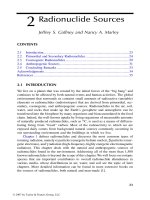
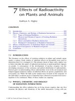
9.3.1 GAS-FILLED DETECTORS
A gas-filled detector is composed of an enclosed gas volume between two elec-
trodes (anode and cathode) (see Figure 9.1). Gas-filled detectors have different
shapes — two parallel electrodes, cylindrical with a central rod as an anode, and
spherical — but they work based on the same principles. When the incident
radiation travels through the gas (the sensitive volume of the detector) and inter-
acts with the gas atoms and molecules, atom excitation and ionization occur. The
gas ionization produces electron-ion pairs; their number depends on the energy
deposited during the radiation-gas interaction. The average energy required to
form one ion pair is about 35 eV, including excitation energy. Ion pairs are
recombined locally after their formation inside the gas volume, if the applied
voltage is low or zero. The electric field (E) between the detector electrodes exerts
electric forces to move the negative electrons toward the anode and the positive
ions toward the cathode. The strength of the electric field E(r) at point P between
the cylindrical detector electrodes is given by
DK594X_book.fm Page 280 Tuesday, June 6, 2006 9:53 AM
© 2007 by Taylor & Francis Group, LLC
Radiation Detection Methods 281
, (9.22)
where
r = distance of point P from the center of the cylinder,
a = radius of the anode,
b = inner radius of cylinder.
Both electrons and positive ions of the gas atom have the same charge and
different masses, where the positive ions are much heavier than the electrons.
The acceleration, a (electric force/mass, in m/s
2
), of an electron is thousands of
times higher than that of the positive ion. The drift velocity of the electrons is
thousands of times faster than that of the positive ion. The output signal is based
on the collected charges (electron and positive ions) and, depending on the
operating mode, the output signal is either a current signal due to the collected
charges (a resistance circuit) or a pulse due the drop in external circuit voltage
at the current saturation condition (a resistance-capacitance circuit). There is a
time difference between the output current signal due to electron collection on
the anode and positive ions collection on the cathode. Practically, the output signal
depends on the electrons charge collection to have a short responding time.
The structural material and design of gas field counters affect the counting
efficiency of different radiation types. For charged particles, the counter windows
should be thin to avoid particle absorption within the counter window. For
β particles, the counter is designed to stand a higher gas pressure, which is
necessary to stop incident β particles with the gas volume of the counter. For
γ-rays, the counter walls are constructed from high atomic number materials,
where the counter response to γ-rays comes through its interaction with the counter
walls. As the applied voltage increases, the electric field strength increases and
the recombination rate decreases to zero (i.e., all created ions are collected). Up
FIGURE 9.1 Basic structure of the gas-filled detector.
+
−
Cathode
Anode
+
−
−
+
+
−
+
+
−
+
−
+
+
−
Battery
Er
V
rba
()
ln( / )
=
DK594X_book.fm Page 281 Tuesday, June 6, 2006 9:53 AM
© 2007 by Taylor & Francis Group, LLC
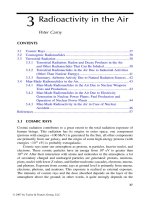
282 Radionuclide Concentrations in Food and the Environment
to this voltage, the region is known as the partial recombination region. The
response curve of gas-filled detectors is shown in Figure 9.2. It is divided into
five regions: recombination, ionization, proportional, Geiger-Muller, and contin-
uous discharge. A gas-filled detector may operate in any of these regions, depend-
ing on the gas type, gas pressure, applied voltage, and counter size.
9.3.1.1 Ionization Chambers
The applied voltage, less than 1000 V, is high enough to collect electrons before
recombination with positive ions. The recombination rate is zero, and even with
an increase in the applied voltage, the collected charge rate stays constant, known
as the ionization chamber plateau. The detector output signal, either current or
pulse, is exactly equivalent to the energy deposited divided by the energy required
to ionize one gas atom (i.e., no amplification). To maintain the ionization chamber
conditions, both the electric field strength (E) and the gas mixture must be
controlled. α particles have a higher specific ionization than that of electrons or
γ rays because of its higher linear energy transfer (energy loss per unit length of
the path). Therefore the ionization chamber has the ability to distinguish between
the different types of radiation and the same radiation with different energies.
The energy resolution (the ability to distinguish between two photons or particles
having different but close energies) of an ionization chamber is quite good.
Ionization chambers are very useful for the measurement of high-radiation fields
and intensities of extended photon emitters. The ionization chamber structure
changes according to the radiation type. It is basically a metal cylinder with a
central anode and its inner walls are usually lined by an air equivalent material.
FIGURE 9.2 Gas-filled detector response curve as a function of the applied voltage.
Anode voltage
Ionization
chamber
Counter discharge
Proportional
counter
500 1000
Ion collected
G-M
Counter
DK594X_book.fm Page 282 Tuesday, June 6, 2006 9:53 AM
© 2007 by Taylor & Francis Group, LLC
Radiation Detection Methods 283
For β particle detection, the entrance window of the detector should be thin to
decrease particle absorption. For β particles, the gas pressure increases to stop
all particles inside the active volume of the chamber to ensure complete particle
energy deposit. For γ-rays, the detector should be lined with a high atomic number
material to increase the probability of γ-ray interaction. Ionization chamber detec-
tors operate in different modes, depending on the output signal: current mode,
charge integration mode, or pulse mode. There are many applications of radiation
detection systems based on ionization chambers, including calibration of radio-
active sources and measurement of gases such as radon.
9.3.1.2 Proportional Counters
As the applied voltage increases (range 800 to 2000 V), the electric field strength
will be strong enough to not only remove the electrons and positive ions of the
primary ionization, but also to accelerate the primary ionization electrons and
positive ions. The accelerated electrons gain a relatively higher kinetic energy
and produce a secondary ionization in the region closed to the anode due to their
collisions with the gas atoms. Also, the accelerated positive ions strike the cathode
and create a secondary ionization. This multiplication process (i.e., primary
ionization multiplication) is known as a Townsend avalanche or Townsend cas-
cade. The height of the output signals is linearly proportional to the energy
dissipated and the primary ionization inside the counter. Thus radiation detection
and energy measurement are possible. As the applied voltage increases, the
proportionality of the output signal to the dissipated energy and the primary
ionization decreases. This range of voltage is known as the limited proportional
region. It is very practical to operate the counter in this range for high-level
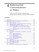
radiation measurements. The proportional counter can distinguish between
α-particles and β electron particles, where the signal from the α particle is larger
than that due to the β signal. In studying the characteristic curve for a proportional
gas counter with an α/β emitter mixed source, as the high voltage increases, only
α particle signals are large enough to pass the discriminator of the counting
channel. The α signal count rate will increase to reach a plateau, known as the
α plateau. The length of the plateau depends on the source properties, being thin
or thick, and the source-detector geometric arrangement, being an internal
(located inside the counter) or external source. As the high voltage increases, the
count rate increases due to β particle signals, until they reach another plateau
where both α and β particles are counted (Figure 9.3). Proportional counters
usually operate in pulse mode.
One of the most important environmental applications of proportional
counters is the low-background total α/β gas flow proportional counter. Generally,
gross counting is very useful for environment sample screening to compare the
radioactivity content of many environmental samples. Proportional counters with
α/β particle discrimination are useful to measure gross α and gross β particles
separately. α/β discrimination is based on the applied voltage and the different
pulse shape, where α particles can be counted in a lower voltage gradient.
DK594X_book.fm Page 283 Tuesday, June 6, 2006 9:53 AM
© 2007 by Taylor & Francis Group, LLC
284 Radionuclide Concentrations in Food and the Environment
α particles have a different pulse shape due to their high specific ionization. The
pulses due to α particles can be discriminated in the presence of β particles, but
β particles cannot be discriminated in the presence of α particles due α-β-cross
talk. It is possible to use gross α/β to determine specific radionuclides such as
137
Cs,
210
Pb, and
90
Sr after radiochemical separation. The detection systems based
on proportional counters have different geometries and applications such as 2π
α-β counters and 4π α-β gas flow counters.
9.3.1.3 Geiger-Muller Counters
As the applied voltage increases (range 1000 to 3000 V), gas multiplication
increases greatly due to the strong applied electric field between the electrodes.
Geiger-Muller counters work in the same manner as proportional counters, the
main difference being that ion pairs form along the radiation track and produce
avalanche. In Geiger-Muller counters, one avalanche can produce another ava-
lanche within the counter sensitive volume and spreads as a chain reaction. So
the output pulses of Geiger-Muller counters are correlated with the original
radiation properties (i.e., all pulses are the same regardless of the initial number
of ion pairs produced by radiation). Geiger-Muller counters can operate as simple
counters and not as spectrometers because it is impossible to differentiate between
the different radiation energies.
Geiger-Muller counters are used as simple, economical radiation counters
with a single electronic process where it does not need amplification of the large
amplitude output signal. One of the main disadvantages of the Geiger-Muller
counter is its long dead time compared to other counters. This limits its use to
low count rate (a few thousand pulses per second) situations. Also the dead time
correction should be considered.
Geiger-Muller counter quenching is another problem that appears as a con-
tinuous output of multiple pulses. The negative ions are collected and produce
the primary discharge of the counter, and then the positive ions slowly drift toward
FIGURE 9.3 Proportional counter response curve for α and α/β particles as a function
of the applied voltage.
α + β
α
Anode voltage
Counts
DK594X_book.fm Page 284 Tuesday, June 6, 2006 9:53 AM
© 2007 by Taylor & Francis Group, LLC
Radiation Detection Methods 285
the cathode where they hit the cathode and produce free electrons. At the cathode
surface, the positive ions are neutralized by combining with an electron released
from the cathode, and the rest of the electrons move toward the anode, leading
to a second discharge. Counter quenching is handled in two ways: externally
through an electronic circuit to decrease the high voltage after the primary
discharge, or internally by mixing quench gas with lower ionization energy to
decrease the production of electrons at the cathode surface and to prevent counter
quenching.
9.3.2 SCINTILLATION DETECTORS
Luminescence processes play a very important role in radiation detection. The
interaction of different radiations with a scintillator will ionize and excite its atoms
and molecules. A large percentage of the absorbed energy is transferred to heat.
After a short time, a small percentage of the deposited energy is released due to
scintillator atom deexcitation that produces fluorescence light, visible light pulses,
known as scintillation. The light pulses (scintillations) are converted to photoelec-
trons that are magnified through the photomultiplier tube to electric signals.
The prompt emission of visible light from a scintillator following its excitation
due to energy absorption is known as the fluorescence process. Delayed fluores-
cence has the same emission spectrum as prompt fluorescence, but with a much
longer emission time. The phosphorescence process corresponds to the emission
of longer wavelength visible light than that of fluorescence and generally with
much slower emission times. The quality and suitability of a scintillator as a
radiation detector depends on its ability to convert as large a fraction as possible
of the incident radiation energy to prompt fluorescence and to minimize the
delayed fluorescence and phosphorescence processes.
The quality of the scintillator as a radiation detector depends on the following
properties:
• Linear response between the deposited energy and the output light
pulse.
• Decay time between the energy absorption and the light emission.
• Radiation energy absorption efficiency, specially for γ rays and neutrons.
• Scintillation efficiency, efficiency of conversion of absorbed energy to
light.
•Transparency to its fluorescence light.
• Its index of refraction.
A high-quality scintillator has a liner response, short decay time, high absorp-
tion and scintillation (emission) efficiencies, a high transparency to its fluores-
cence photons, good optical quality, and an index of refraction near that of glass
(1.5) to permit efficient coupling to the photomultiplier tube.
Radiation detection systems based on scintillation detectors consist of three
main components: a scintillator (including the sensitive volume of the detector),
DK594X_book.fm Page 285 Tuesday, June 6, 2006 9:53 AM
© 2007 by Taylor & Francis Group, LLC
286 Radionuclide Concentrations in Food and the Environment
an optical coupling system, and a photomultiplier tube and signal possessing
electronic. The NaI(Tl) scintillation detector structure is shown in Figure 9.4. The
outer surface of the scintillator (the sensitive volume of the detector) is optically
isolated inside a holding vessel where the outer surfaces are constructed from
reflecting materials. The side of the scintillator facing the photomultiplier tube
is transparent to allow the passage of the produced light pulses — scintillation —
due to the interaction of radiation within the scintillator. The light is emitted
isotropically and somehow has to be channeled toward the photomultiplier tube.
Any loss at this stage reduces the signal pulse height, decreases the low-energy
sensitivity, and degrades the energy resolution. The optical coupling system may
vary from virtually nothing to a highly sophisticated arrangement to ensure the
efficient transfer of the light pulse from the scintillator to the photomultiplier
tube. The photomultiplier tube consists of a photosensitive layer (photocathode)
and 9 to 12 dynodes where the applied positive voltage increases gradually by
about 100 to 200 V for each dynode and anode. The photons produced in the
scintillator hit the photocathode and release a number of electrons that gain kinetic
energy, due to the potential difference between the photocathode and the first
dynode, and hit the first dynode and release five to eight electrons. The maximum
values of quantum efficiency, the fractional number of electron released per
photon, are 0.2 to 0.3 and depend on the wavelength of the light. The produced
photoelectrons are internally multiplied due to an increase in the applied voltage
on the dynodes that generate a relatively large electric pulse output at the anode,
which is nearly proportional to the energy absorbed in the scintillator. Therefore
the radiation detection process with a scintillation detector includes energy
absorption in the scintillator, conversion of the absorbed energy to light photons,
loss of photons in the scintillator, collection of photons and emission of electrons
by the photocathode, electron multiplication in the photomultiplier tube (PMT),
and finally output electric pulse analysis.
The number of electrons, n
e
, released at the photocathode per absorbed energy
(in keV), E
a
, is given by
n
e
= E
a
ST
p
GC, (9.23)
FIGURE 9.4 Cross section of NaI(Tl) inorganic scintillator crystal with photomultiplier
tube (PMT).
+ve Anode
NaI(Tl)
Crystal
Dynodes
Photo-
cathode
P
h
otomu
l
tip
l
ier tu
b
e
Optical
coupling
DK594X_book.fm Page 286 Tuesday, June 6, 2006 9:53 AM
© 2007 by Taylor & Francis Group, LLC
Radiation Detection Methods 287
where
S = scintillation efficiency (the number of photons converted to light
per keV),
T
p
= fraction of photons not absorbed in the scintillator,
G = light collection efficiency (the fraction of photons that fall on the
photocathode),
C = quantum efficiency (the fractional number of electrons released
per photon hitting the photocathode).
Scintillation detectors allow the measurement of radiation intensity, with a
higher efficiency than that of Geiger-Muller counters, especially for γ-rays, and
the determination of deposited energy. They can be used to measure radiation
intensity and as a spectrometer to measure the energy spectrum of radiation.
9.3.2.1 Inorganic Scintillators
The inorganic crystal scintillators are mainly alkali halides such as sodium iodide
or cesium iodide. They have a high atomic number, high densities, and high light
output, so they are the most widely used especially for γ-ray detection. There are
two types of inorganic crystal scintillators: pure or intrinsic crystals such as NaI
and CsI and doped or extrinsic crystals such as NaI(Tl), CsI(Tl), and CaI
2
(Tl).
Thallium is a high atomic number element, which is added to the pure crystal as
impurities and is known as activator.
The scintillation mechanism in inorganic materials depends on the energy
states or bands determined by the crystal lattice of the material. Normally elec-
trons are bound at lattice sites. The lower energy band is known as the valence
band. The next energy band is the conduction band, which is usually empty.
Energy dissipated in the material removes electrons from the lattice sites to the
conduction band, which becomes free to move anywhere in the lattice and leaves
a positive hole in the valence band, which can also move. Sometimes the absorbed
energy is not enough to elevate the electron to the conduction band. Instead, the
electron remains electrostatically bound to the positive hole in the valence band
(i.e., excitation). Energy gaps, in which electrons can never be found in the pure
crystal, exist between the valence and conduction bands. As a result of the
interaction of radiation with the scintillator crystal, the electron can gain enough
energy to rise from the valence band to the higher energy level of the conduction
band and leave a positive hole in the valence band. In the pure crystal, after a
certain decay time, an electron returns to the valence band with the emission of
a photon. This process is inefficient and the librated photon energy is too high
to lie in the visible range where most photomultiplier tubes respond best. A small
amount of an impurity (i.e., activator) is added to enhance the probability of
visible light photon emission during the deexcitation process. Activators such as
thallium will change the energy band arrangement in some lattice sites where
additional energy bands exist in the forbidden energy band of the pure crystal,
DK594X_book.fm Page 287 Tuesday, June 6, 2006 9:53 AM
© 2007 by Taylor & Francis Group, LLC
288 Radionuclide Concentrations in Food and the Environment
as shown in Figure 9.5. The deexcitation of electrons through the activator energy
bands, which have a lower energy gap, will produce photons, which lie in the
visible range and are the basis for an efficient scintillation process. So the output
light pulse is produced as a result of activator atom transitions (i.e., deexcitation),
with typical half-lives on the order of 10
–7
sec.
There are other processes that compete with the scintillation process, such
as phosphorescence and quenching. Phosphorescence can often be a significant
source of background light. Quenching represents a loss mechanism in the con-
version of radiation energy to scintillation light due to certain radiationless tran-
sitions. The magnitude of the light output (i.e., the scintillation efficiency) and
the wavelength of the emitted light are the most important characteristics of any
scintillator. Scintillation efficiency and the wavelength of the emitted light affect
the number of photoelectrons released from the photocathode and the pulse height
at the output of the detection system.
The most widely used inorganic scintillator for γ-ray measurement uses a
NaI(Tl) crustal. It has an excellent light yield, a linear response to electrons and
γ-rays over most of the significant energy range, and a high atomic number. It
can be manufactured in large sizes and different shapes. NaI(Tl) is hygroscopic,
somewhat fragile, and can be easily damaged by mechanical or thermal shock.
Various experimental data have shown that the absolute efficiency of NaI(Tl) is
about 12%.
Other inorganic scintillators, including CsI(Tl), CsI(Na), CaF
2
(Eu), LiI(Eu),
bismuth germanate, BaF
2
, ZnS(Ag), and CaF
2
(Eu) have different densities, light
conversion efficiencies, and wavelength ranges of the emission spectra. Details
can be found in various references [1–3].
9.3.2.2 Organic Scintillators
Organic scintillators belong to the class of aromatic compounds and consist of
an organic solvent such as toluene or xylene with low concentrations of one or
more additives known as solutes. Organic scintillators are either used as pure
organic crystals or as liquid organic solutions or polymers known as plastic
scintillators.
FIGURE 9.5 Energy bands for pure crystal and crystal with activator material.
Conduction band
Valence band
Excitation state
Activator
Energy gap
Excitation state
Ground state
Crystal with activatorPure crystal
DK594X_book.fm Page 288 Tuesday, June 6, 2006 9:53 AM
© 2007 by Taylor & Francis Group, LLC
Radiation Detection Methods 289
The scintillation process in organic scintillators is the result of molecular
transitions and is not affected by the physical state of the scintillator (i.e., crys-
talline solid, vapor, or liquid). A more detailed description of the scintillation
process can be found in various references [1–3]. The main advantage of organic
scintillators over inorganic scintillators is their fast response time, which is less
than 10 nsec for organic scintillators and about 1 µsec for inorganic scintillators.
This makes organic scintillators suitable for fast timing measurements. The scin-
tillation efficiency for inorganic scintillators is generally higher than that of
organic scintillators. For example, the scintillation efficiency of anthracene, which
has the highest scintillation efficiency of all organic scintillators, is only about
one third that of NaI(Tl) crystals. Beside the scintillation of the organic molecule
following deexcitation, there are other radiationless deexcitation processes, called
quenching. Quenching increases with increasing impurities, such as dissolved
oxygen, in liquid scintillators. Although prompt fluorescence represents most of
the observed scintillation, delayed fluorescence is also observed in many cases.
Delayed fluorescence often depends on the nature of the exciting radiation and
the rate of energy loss (dE/dx) of the exciting particle. The α and β particle pulse
shapes are shown in Figure 9.6. Pulse shape analysis or discrimination is used
to differentiate between different kinds of radiation particles, where the decay
time of the pulse due to α particles is longer than that due to β particles.
There are different types of organic scintillators, including pure organic
crystal, liquid organic solution, and plastic scintillators. Each has certain advan-
tages and disadvantages for particular applications. The dissipated energy in pure
organic scintillators transfers between molecules before deexcitation occurs. The
energy dissipated in liquid and plastic scintillators is primarily absorbed by the
solvent then transferred to the solute molecules, which are the efficient scintilla-
tion molecules where light emission occurs. Anthracene and stilbene are most
common and are used as pure organic crystal scintillators. Anthracene has the
highest scintillation efficiency of any organic scintillator. Stilbene has lower
FIGURE 9.6 α and β particle pulse shapes.
α
β
Time
Intensity
DK594X_book.fm Page 289 Tuesday, June 6, 2006 9:53 AM
© 2007 by Taylor & Francis Group, LLC
290 Radionuclide Concentrations in Food and the Environment
scintillation efficiency, but is more suitable to differentiate between different kinds
of radiation particles by pulse shape discrimination. Both materials are relatively
fragile and difficult to obtain in large sizes.
Liquid organic scintillators and plastic scintillators have the same composi-
tion, but different physical forms. They are composed of solvent, which is a liquid
for liquid organic scintillator and a polymer for plastic scintillators, and one or
more solutes. One of the solutes is sometimes added to serve as a wave shifter.
It absorbs the light produced by the primary solute and reradiates it at a longer
wavelength to match the spectral sensitivity of the photomultiplier tube or to
minimize bulk self-absorption in large liquid or plastic scintillators. Liquid
organic scintillators have many applications in nuclear and environmental field
measurements, especially for α and β particles. Liquid scintillators are used in
sealed containers, which can reach few meters in size, and are handled in the
same manner as solid scintillators. Liquid scintillators can be mixed with liquid
samples for 4π configuration measurement, with nearly 100% counting efficiency.
9.3.3 SEMICONDUCTOR DETECTORS
Semiconductors are materials that do not have enough free charge carriers to
behave as electrical conductors or a high resistivity to act as electrical insulators.
As we mentioned before, the solid crystal has three energy bands: the valence
band, the conduction band, and the forbidden band. For electrical conductors, the
width of the forbidden energy band is very small. This allows the movement of
valence electrons to the conduction band under the effect of any electric field
strength higher than zero, where the electrons can move freely in the crystal
lattice and carry electric current. For electrical insulators, the width of the for-
bidden energy band is large (about 10 eV) enough to prevent the movement of
valence electrons to the conduction band, which is completely empty. For semi-
conductor materials, the forbidden energy band is relatively narrow, to prevent
the movement of electrons to the conduction band at low temperatures (i.e., the
conductivity of the semiconductors is zero). As temperature increases, some
electrons gain enough energy to cross the forbidden band to the conduction band,
where electrons can carry electric current under the influence of an electric field
in the same way as conductors.
Semiconductor crystals as a detector material should have the capability of
supporting large electric field gradients, high resistivity, and exhibit long life and
mobility for both electrons and holes. If the mobility is too small and lifetime is
too short, most electrons and holes will be trapped in crystal lattice imperfections
or recombine before they can be collected. The group IV elements silicon and
germanium are the most widely used semiconductor crystal as radiation detectors.
Some of the key characteristics of various semiconductors for radiation detectors
are shown in Table 9.1. The conductivity of semiconductors increases with an
increase in the concentration of impurities, which create new energy levels that
facilitate the movement of the carrier within the crystal. The ideal semiconductor
material is “intrinsic” or “low effective impurity” material that is produced by a
DK594X_book.fm Page 290 Tuesday, June 6, 2006 9:53 AM
© 2007 by Taylor & Francis Group, LLC
Radiation Detection Methods 291
process called “doping,” which involves the addition of an impurity to reduce the
charge carrier concentration (i.e., adding an electron-accepting impurity to com-
pensate for electron donor impurities). Although doping increases the resistivity
of the material, it also increases the probability of electron hole trapping or
recombination. Prior to the mid-1970s, the required purity level of silicon and
germanium could be achieved only by lithium ion drifting, counterdoping P-type
(electron acceptor) crystals with N-type (electron donor) impurity to produce
Ge(Li) and Si(Li) crystals. Since 1976, sufficient pure germanium has been
available, but the doping process is still widely used in the production of Si(Li)
x-ray detectors.
Semiconductors have four valence electrons in the upper energy level of the
valence band. If they are doped with atoms, as crystal impurity, with three valence
electrons, such as gallium, positive holes will be created in the crystal, known as
P-type crystal, and the holes are the major current carrier. If they are doped with
atoms with five valence electrons, such as arsenic, excess electrons will be created
in the crystal, known as N-type crystal, and the electrons are the major current
carrier. Semiconductors have a P-N diode structure and radiation detection is
based on the favorable properties of the intrinsic region, the region near the
junction between N- and P-type semiconductor materials, which is created by
the depletion of charge carriers. The depletion region is the sensitive volume of
the semiconductor detector where the ionizing radiation interacts and the dissi-
pated energy produces electron hole pairs in the same way as gas-filled detectors.
Electron-hole pairs are swept to the P and N regions. The produced charge is
linearly correlated to the energy deposited in the detector. Semiconductors might
be considered as solid state ionization chambers, with several advantages over
gas devices. An unbiased P-N junction can act like a detector, but only with very
poor performance, because the depletion region thickness is quit small, the junc-
tion capacitance is high, and the spontaneous electric field strength across the
junction is low and not enough to collect the induced charge carriers that could
be lost due to trapping and recombination. The performance of the P-N junction
as a radiation detector is improved by applying an external voltage that causes
TABLE 9.1
Some Key Characteristics of Various
Semiconductors as Detector Materials
Material Z Band gap (eV) Energy/E
h
pair (eV)
Si 14 1.12 3.61
Ge 32 0.74 2.98
CdTe 48–52 1.47 4.43
HgI
2
80–53 2.13 6.5
GaAs 31–33 1.43 5.2
DK594X_book.fm Page 291 Tuesday, June 6, 2006 9:53 AM
© 2007 by Taylor & Francis Group, LLC
292 Radionuclide Concentrations in Food and the Environment
the junction to be reversed biased. As the applied voltage increases, the width
of the depletion region and the sensitive volume increase and the performance of
the detection is improved. The applied voltage should be kept below the break-
down voltage of the detector to avoid catastrophic deterioration of the detector
properties.
Because of the narrow energy band gap, 0.74 eV for germanium and 1.12 eV
for silicon, semiconductor detectors are thermally sensitive. Both germanium and
silicon photon detectors are cooled with liquid nitrogen during operation to reduce
the thermal charge carrier generation (noise) to an acceptable limit, where the
reverse leakage currents are in the range of 10
–9
to 10
–12
amp at liquid nitrogen
temperature (77˚K). The narrow energy band gap of semiconductor materials is
1/10 that required to produce an electron hole pair in a gas. This gives them the
advantage of better energy resolution over gas-filled and scintillation detectors,
where the increase in the number of charge carriers in the semiconductor detector
leads to improved statistics and better energy resolution. The excellent energy
resolution of semiconductor detectors is due to the much larger number of charge
carriers per pulse (i.e., they produce a much larger number of charge carriers for
a given incident radiation than is possible with any other detector type). The
energy resolutions of different radiation detectors are given in Table 9.2. A
comparison of different detector energy resolution is shown in Figure 9.12.
Germanium is widely used for γ- and x-rays, while silicon is used for x-rays as
Si(Li) and charged particles as silicon surface barrier detectors. NaI(Tl) scintil-
lator has a relatively greater detection efficiency than that of semiconductor
detectors because of its high atomic number. Semiconductor detectors for γ- and
x-ray spectroscopy have several advantages over NaI(Tl) scintillators; among
these are high energy resolution, compact size, relatively fast timing character-
istics, and an effective thickness. Their disadvantages include the limitation to
small sizes, some of them need to be cooled, and their relative sensitivity to
performance degradation from radiation-induced damage.
TABLE 9.2
Energy Resolution (FWHM)
for Different Detector Types
Energy (keV) 59 122 1332
Proportional counter 1.2 — —
X-ray NaI(Tl) 3.0 12.0 —
3
× 3 NaI(Tl) — 12.0 60
Si(Li) 0.16 — —
Planar Ge 0.18 0.5 —
Coaxial Ge — 0.8 1.8
DK594X_book.fm Page 292 Tuesday, June 6, 2006 9:53 AM
© 2007 by Taylor & Francis Group, LLC
Radiation Detection Methods 293
9.3.3.1 Germanium Detectors
Germanium detectors are made of hyperpure germanium (HPGe) crystal that is
mounted in a vacuum chamber. They are cooled by a liquid nitrogen cryostat to
reduce the leakage current to an acceptable level. The preamplifier is located near
the detector as part of the cryostat package to reduce electronic noise. A cross
section of a typical HPGe detector with the liquid nitrogen cryostat is shown in
Figure 9.7. There are different types of germanium detectors: coaxial, planar, and
well. Their geometry and construction features are shown in Figure 9.8. The
geometry and construction features of the detector affect its detection features,
such as detection efficiency for γ- and x-rays, energy range, and energy resolution.
Variations in detector efficiency and energy resolution as a function of incident
radiation energy for the different detector types are shown in Figure 9.9 and
Figure 9.10. Coaxial P-type germanium detectors are used for γ-rays, with an
energy range of 100 keV to about 10 MeV, and cannot be used for low-energy
γ- and x-rays because they cannot penetrate the aluminum detector window and
high-energy γ-rays might pass through the sensitive volume without interaction.
For x-ray spectroscopy, N-type and planar germanium detectors can be used
because of the thin beryllium entrance windows. At low energies, detector effi-
FIGURE 9.7 Cross section of a HPGe detector with liquid nitrogen cryostat.
Detector holder
End cap
Tai l stock
LN transfer
collar
Necktube
Dewar
Coldfinger
Electric feedthrough
Preamp. housing
Fill/vent tubes
Molecular
sieves
Super-insulation
DK594X_book.fm Page 293 Tuesday, June 6, 2006 9:53 AM
© 2007 by Taylor & Francis Group, LLC