Báo cáo sinh học: " This peer-reviewed article was published immediately upon acceptance. It can be downloaded, printed " ppt
Bạn đang xem bản rút gọn của tài liệu. Xem và tải ngay bản đầy đủ của tài liệu tại đây (1.78 MB, 16 trang )
This Provisional PDF corresponds to the article as it appeared upon acceptance. Fully formatted
PDF and full text (HTML) versions will be made available soon.
Critical aspects of substrate nanopatterning for the ordered growth of GaN
nanocolumns
Nanoscale Research Letters 2011, 6:632 doi:10.1186/1556-276X-6-632
Francesca Barbagini ()
Ana Bengoechea-Encabo ()
Steven Albert ()
Javier Martinez ()
Miguel Angel Sanchez-Garcia ()
Achim Trampert ()
Enrique Calleja ()
ISSN 1556-276X
Article type Nano Express
Submission date 24 August 2011
Acceptance date 14 December 2011
Publication date 14 December 2011
Article URL />This peer-reviewed article was published immediately upon acceptance. It can be downloaded,
printed and distributed freely for any purposes (see copyright notice below).
Articles in Nanoscale Research Letters are listed in PubMed and archived at PubMed Central.
For information about publishing your research in Nanoscale Research Letters go to
/>For information about other SpringerOpen publications go to
Nanoscale Research Letters
© 2011 Barbagini et al. ; licensee Springer.
This is an open access article distributed under the terms of the Creative Commons Attribution License ( />which permits unrestricted use, distribution, and reproduction in any medium, provided the original work is properly cited.
- 1 -
Critical aspects of substrate nanopatterning for the ordered growth
of GaN nanocolumns
Francesca Barbagini*
†1
, Ana Bengoechea-Encabo
†1
, Steven Albert
†1
, Javier
Martinez
†1
, Miguel Angel Sanchez García
†1
, Achim Trampert
†2
, and Enrique Calleja
†1
1
ISOM and Electrical Engineering Dept. (DIE), Escuela Técnica Superior de
Ingenieros de Telecomunicaciónes (ETSIT), Universidad Politécnica de Madrid s/n,
Madrid, 28040, Spain
2
Paul Drude Institut für Festköperelektronik, Hausvogteiplatz 5-7, Berlin, 10117,
Germany
*Corresponding author:
†
Contributed equally
Email addresses:
FB:
ABE:
SA:
JM:
MASG:
AT:
EC:
- 2 -
Abstract
Precise and reproducible surface nanopatterning is the key for a successful
ordered growth of GaN nanocolumns. In this work, we point out the main
technological issues related to the patterning process, mainly surface roughness and
cleaning, and mask adhesion to the substrate. We found that each of these factors,
process-related, has a dramatic impact on the subsequent selective growth of the
columns inside the patterned holes. We compare the performance of e-beam
lithography, colloidal lithography, and focused ion beam in the fabrication of hole-
patterned masks for ordered columnar growth. These results are applicable to the
ordered growth of nanocolumns of different materials.
Keywords: GaN nanocolumns; ordered growth; molecular beam epitaxy; surface
cleaning; roughness; adhesion; e-beam lithography; colloidal lithography; focused ion
beam.
Background
The unique properties of III-nitride nanocolumns [NCs] in contrast to thin film
structures derive from the reduced footprint on the substrate that enables essentially
dislocation- and strain- free growth on a variety of substrates [1]. Defect-free NCs
exhibit excellent electronic transport and optical properties for the fabrication of high-
efficiency optoelectronic nanodevices, such as photodetectors, light-emitting diodes,
and solar cells [2-5]. Moreover, the controlled coalescence of III-nitride NCs would
lead to strain-free pseudosubstrates with reduced defect densities [6].
During the past years, III-nitride NCs have been grown in the self-assembled
mode by plasma-assisted molecular beam epitaxy [PA-MBE] [7-9] on various
substrates. However, fluctuations in density and dimensions of the NCs lead to
significant dispersion in the optoelectronic properties and render the device
processing very difficult. Thus, the realization of true devices relies on the
achievement of ordered arrays of homogeneous NCs by localization of the epitaxial
growth on predetermined preferential sites. This growth mode is known as selective
area growth [SAG], and it has attracted much scientific interest in the last few years
[10-15].
In the SAG, the substrate is pre-patterned with a mask of nanoholes. The NCs
nucleate and grow selectively inside the nanoholes and not on the surface of the mask.
Many experimental works have been reported on the SAG of GaN/InGaN
nanocolumnar heterostructures [10-14]. In these works, the hole patterning of the
mask material was achieved either by focused ion beam [FIB] or by e-beam
lithography [EBL]. However, despite the fundamental importance of the
nanopatterning process, no detailed information has been reported neither on the
choice of the particular nanopatterning technique nor on the importance of the
morphology of the patterned mask with respect to the subsequent selective growth.
Within this context, the quality of the surface pattern is crucial because it determines
whether selectivity is achieved or not.
This work studies the hole patterning of the mask material for the subsequent
SAG of GaN NCs by PA-MBE. Three different techniques are reported that were
successfully used to pre-pattern the surface of a thin Ti mask with ordered arrays of
nanoholes: EBL followed by dry etch, colloidal lithography [CL], and FIB. The
- 3 -
critical issues encountered in the mask fabrication processes are studied in detail.
More specifically, the effects of surface roughness, adhesion of the mask layer to the
substrate, and surface cleanliness on the following GaN NCs SAG are analyzed. For
each of the mentioned techniques, the main advantages and drawbacks are
highlighted. Only when the patterning process was optimized, high-quality hole-
patterned masks of different dimensions and geometry were obtained. These masks
were subsequently used to grow ordered crystalline GaN NCs in the SAG mode by
PA-MBE. The technological issues discussed in this work can be applied to the
ordered growth of any kind of material on various substrates.
Methods
Substrate nanopatterning
All substrates used in this work were commercial 2-in. wafers consisting of a
4-µm GaN (0001) layer grown on sapphire by MOVPE (Lumilog, Les Moulins,
Vallauris, France). These substrates were cleaned in N-methyl-pyrrolidone [NMP] at
90°C for 30 min, rinsed in isopropanol [IPA], and thoroughly cleared with deionized
[DI] water. The mask material always consisted of a 5- to 10-nm Ti
layer deposited on
a clean GaN template by e-beam evaporation. The root mean square [RMS] roughness
of the wafer surface before and after Ti deposition was 0.4 ± 0.1 nm in an area of 1
µm
2
. The various techniques used to pattern the Ti mask with ordered arrays of
nanoholes are described in detail in the following subparagraphs. Prior to each PA-
MBE growth, the distribution, diameter, and depth of the nanoholes were
characterized by atomic force miscroscopy [AFM] (Nanoscope III Multimode AFM,
Veeco Instruments Inc., Plainview, NY, USA) and scanning electron microscopy
[SEM] (CABL-9500C, Crestec Co. Ltd., Hamamatsu, Shizuoka, Japan).
E-beam lithography
A 350-nm layer of positive resist ZEP520A (Zeon Co., Tokyo, Japan) was
spun at 4,000 rpm on the Ti mask. After baking at 190°C for 2 min, the sample was
transferred to the EBL system. The nanoholes were opened in the resist using a
current of 0.5 × 10
−9
A, and an exposure time ranging from 15 to 45 µs. The process
conditions were optimized to obtain arrays of nanoholes with diameters ranging from
50 to 200 nm and pitch (center-to-center distance) varying from 80 nm to 300 nm.
After developing the resist, the sample was dry-etched in O
2
/CF
4
plasma at 10
−2
mbar
and 110 W (Plasmalab, Oxford Instruments plc, Abingdon, Oxfordshire, UK) for 130
s. The post-etch residue was removed by immersing in NMP at 80°C for 30 min and
abundantly rinsing in IPA and DI water. In some cases, oxygen plasma was necessary
to completely remove the resist hardened by the previous plasma etching. AFM
analysis revealed an etching depth between 7 and 10 nm; thus, the GaN material
underneath the Ti mask was also etched some 2 to 5 nm.
Colloidal lithography
This method was extensively introduced elsewhere [16]. Briefly, the GaN substrate
was made negatively charged by coating with a trilayer of polyelectrolytes.
Monodispersed sulfate latex spheres (mean diameter of 260 nm; Invitrogen, Carlsbad,
CA, USA) were spun on GaN from aqueous solutions to obtain a densely packed
monolayer of nanospheres. Subsequent oxygen plasma was used to reduce the sphere
dimensions thus creating some sphere-to-sphere interspace. A 5- to 10-nm Ti layer
was evaporated on top, and the spheres were finally stripped from the sample using an
- 4 -
adhesive pad. The final cleaning step consisted of using NMP at 90°C to dissolve any
latex residue from the nanoparticles and thoroughly rinsing with DI water.
Focused ion beam
The nanoholes were opened in the 7-nm Ti mask on GaN by a focused ion beam in a
one-step process. The liquid-metal ion source used was Ga
+
at 30 KeV (ionLine Raith
GmbH, Dortmund, Germany). The process conditions were optimized to obtain arrays
of nanoholes with a 100-nm diameter and 250-nm pitch (30 pA, ion dose 10
17
cm
−2
).
No extra cleaning steps were applied after the ion etching. AFM analysis revealed an
etching depth between 10 and 15 nm. Little redeposition of Ti (1 to 2 nm) appears in
some cases at the edges of the holes.
Ordered nanocolumnar growth
GaN NCs were grown on the hole-patterned masks using radio frequency [RF] PA-
MBE (Compact 21, Riber, USA). The substrate temperature during growth was
measured with a thermocouple located at the growth stage. The Ga and N fluxes were
calibrated in equivalent (0001) GaN growth rate units for compact layers in
nanometers per minute, which are the standard units used in nitride PA-MBE growth
diagrams. The Ti mask was nitrided prior to growth to prevent its degradation due to
the high temperatures used in GaN NCs SAG (860°C to 900°C). We used a two-step
nitridation process, as proposed by Sekiguchi et al. [10, 11]: 10 min at 460°C
followed by 3 min at 880°C. During nitridation, the plasma power was set to 580 W
and the nitrogen flux, to 1.2 sccm. These conditions correspond to an equivalent
stoichiometric GaN growth rate higher than 30 nm/min. Electron energy loss
spectroscopy measurements proved the formation of TiN, which is more stable than
Ti at high temperatures. During the growth phase, we lowered the plasma power and
the nitrogen flux to 150 W and 0.3 sccm, respectively. The GaN flux is maintained at
a corresponding GaN growth rate of 16 nm/min. These conditions resulted in a highly
selective ordered growth inside the nanoholes, as widely illustrated in a previous
publication [13].
Results and discussion
The mask fabrication process consists of many critical steps that, in the worst
case scenario, might lead to the total failure of the selective growth. The factors to
account for can be basically summarized into surface roughness, surface cleaning, and
adhesion of the mask material to the substrate. Each of them is treated separately in
the following subparagraphs.
Surface roughness
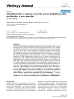
Figure 1 shows the case of a smooth EBL mask surface (Figure 1a), the case
of an EBL mask with local increase in roughness in the 20-nm region around the
holes' rim (Figure 1b), and the case of a FIB mask with bumps in the 20-nm region
around the holes' rim (Figure 1c). In the case of Figure 1a, the surface roughness of
the mask as measured by AFM is 0.5 ± 0.1 nm, which is similar to the RMS values of
both the bare GaN template and the as-deposited Ti layer. These roughness values
lead to PA-MBE growth with a perfect (100%) selective nucleation of NCs inside the
holes (Figure 1d). On the contrary, accurate AFM analysis of the masks in Figure 1b,c
revealed the presence of material around the holes' rim that locally increased the
surface roughness by 1 nm or higher. In the case of EBL masks (Figure 1b), this
particular morphology is attributed to the redeposition of etched material around the
- 5 -
holes during the plasma etch, whereas surface bumps around the holes in FIB masks
are probably formed when bombarding the Ti with a high Ga dose. Both these cases
resulted in a typical donut-shaped growth, where many thin NCs nucleate around the
holes' rim leaving the holes core empty, as shown in Figure 1e,f. In about 50% of the
cases, single tubular NCs were observed, as shown in Figure 1f. It was demonstrated
[17] that surface migration of ad-atoms is the main contribution for selective growth
when using Ti masks. This peculiar growth layout is thus likely due to the difficulty
for the Ga and N ad-atoms to diffuse from the surface into the holes due to either the
deposited material or bumps that act as diffusion barriers. For this reason, the NCs
nucleate at the perimeter of the donut-shaped bumps. The presence of accumulated
material around the holes can only be detected by accurate AFM analysis, while SEM
pictures show smooth surfaces even when there is local increase in RMS. To
minimize this material redeposition and achieve optimal roughness conditions, we
optimized both the plasma etch in EBL technique (mainly plasma power and time)
and the dose in the FIB. In particular, the EBL and etch processes were optimized
using three series of samples. First, the EBL dose was varied until finding the
minimum dose required to open sufficiently wide holes that subsequently enabled to
completely etch the Ti layer underneath. In the second series of samples, we thus used
this optimal EBL conditions and increased the RF power during etch, until the
material redeposition around the holes was minimized. In the last series of samples,
we maintained constant EBL conditions and RF power during the etching while
slightly reducing the etching time in order to leave the surface roughness as low as
possible and ensuring to etch the complete Ti layer and 1-2 nm of the underneath GaN
material. SEM and AFM studies of the holes geometry and of the surface roughness
were measured at the end of the complete processing for each series of samples. For
the FIB optimization, several dose studies were necessary in order to obtain the best
conditions to pattern holes with a depth of 7 nm. An array of holes with similar
diameter (100 nm) but different doses was patterned on a small piece of Ti (7-nm
thickness) on GaN. After the patterning, the depth of the nanoholes and the surface
roughness of the Ti were measured by AFM. The hole with the right depth and no
bumps at the surface was considered as the optimal dose for the FIB. In our case, the
optimal ion dose was 10
17
cm
−2
. The surface roughness was never an issue when
preparing the masks by CL since there was no etching involved.
Surface cleaning of the hole-patterned mask
When the surface of the patterned mask present resist residues, as shown in
Figure 2a,c (SEM and AFM, respectively), GaN NCs still nucleate inside the holes
and exhibit constant distribution, height, and diameter. However, in the spots where
the resist residues lie, thinner NCs nucleate on the mask and grow faster than the
ordered ones inside the holes. These growth results are displayed in Figure 2b,d (top
view and side view, respectively). In principle, organic contaminants, including resist
residues, should evaporate during the nitridation at high temperature. However,
similar growth features were always observed when some resist residues were present
on the mask before the growth. In addition to this, we highlight in general on the
detrimental effect of organic contamination on the subsequent growth. This point
sounds trivial, though it is not always straightforward to identify resist residues over
the mask or inside the holes, due to the high aspect ratio of the patterns and to the
finite dimensions of the AFM tip. In 50% of the cases, neither SEM nor AFM analysis
of the patterned mask showed any surface contamination before the growth. However,
from the growth results, we deduced that contamination occurred at some point during
- 6 -
the mask fabrication. When organic contamination occurred inside the holes only,
non-uniform growth was observed, where the contaminated holes exhibited no
nucleation at all.
Surface cleaning is thus a key point to consider in any method of mask
preparation. However, the plasma-hardened photoresist is very difficult to remove
compared to common organic contaminants. For this reason, the issue of surface
cleaning becomes even more important when preparing the masks by EBL. The
optimal cleaning process for EBL masks before loading the sample in the PA-MBE
chamber consisted of 30 min immersion in pyrrolidone at 80°C followed by a hot
isopropanol rinse and abundant hot water rinse. Finally, a 15-s oxygen plasma was
performed.
Adhesion of the Ti mask to the substrate
A thick Ti layer barely adhered to the GaN substrate material resulted in
delamination of the mask during the MBE growth, as shown in Figure 3a. This
delamination was observed when the PA-MBE growth stage cooled down after
growth from 650°C to 700°C, to room temperature. This issue was solved by
optimizing both the adhesion of the Ti film to the substrate and the thickness of the Ti
film. To improve adhesion, the initial GaN template (as received) was cleaned with
NMP at 90° by sweeping the surface several times with a soft stick, then abundantly
rinsing with IPA and DIW. Prior to Ti deposition, the substrate was heated up in an
oven at 300°C for 30 min to desorb water molecules from the surface. The optimal
thickness of the Ti layer was found empirically. Since the mask adhesion was
optimized, delamination was probably due to the strain generated by thermal shock
when cooling down the system. To decrease the amount of strain, the thickness of the
Ti mask was reduced from 10 nm to 7 nm. A thinner mask resulted in most cases in
the complete degradation of the Ti material at high temperature during the growth, as
shown in Figure 3b. Mask adhesion to the substrate is a factor to consider in all of the
proposed methods, meaning EBL, FIB, and CL. Both optimal substrate cleaning and
mask thickness are of fundamental importance for a good adhesion of the Ti layer to
the substrate.
Despite all these technical issues, high-quality nanopatterned masks were
successfully fabricated using all of the three techniques by optimizing the process
parameters. Typical examples of hole-patterned Ti masks as obtained by EBL, CL,
and FIB are shown in Figure 4a,c,e, respectively. In all cases, the diameter of the
holes varies between 50 nm and 250 nm, and the pitch, between 80 nm and 350 nm.
Using these masks, selective nucleation and growth of GaN NCs inside the holes were
achieved by PA-MBE, independent of the characteristic mask dimensions (within the
above mentioned range) and of the particular patterning technique. These growth
results are shown in Figure 4b,d,f for each of the respective masks. Ordered GaN NCs
always exhibited a constant diameter and interdistance that fit to the geometry of the
initial patterned mask, meaning that the vertical growth rate was much higher than the
lateral one. After 30 min of growth, all the GaN NCs have a
constant height of about
200 nm and show a perfect hexagonal cross section. The latter can be better
appreciated in Figure 1d, which shows a top view of the ordered NCs. High ordering
and constant geometrical parameters (pitch, diameter) were easily achieved in the case
of both EBL and FIB. In the case of colloidal lithography, however, we stress on the
extraordinary level of ordering and homogeneity in the diameter of the holes and pitch
- 7 -
over large areas of several microns, despite the simplicity of the process. Only
localized areas show little defects such as a larger hole or a missed hole. These defects
are due to agglomeration of particles during deposition or to a missed particle in the
initial nanosphere monolayer.
Figure 5a,b shows the TEM analysis of a single GaN NC. In particular, Figure
5b is a magnification at the NC/GaN template/Ti interface. The diffraction contrast
image, which is sensitive to crystal defects, exhibits dark contrast lines that give
evidence for the presence of stacking faults at the NC/GaN template interface.
However, it is clearly shown that the stacking faults cross the whole rod and do not
lead to the formation of partial dislocations. The small footprint and the large surface
area (high aspect ratio) of NCs are known to induce strain-free growth. Initial
dislocations, either from the substrate or generated during the nucleation stage, bend
to the lateral surface [1, 2]. Moreover, the initial GaN template consisted of a 4-µm
strain-free GaN layer on sapphire, and the NCs growth is homoepitaxial. For all the
mentioned reasons, we conclude that there is no epitaxial strain involved. The
presence of stacking faults at the bottom of the NCs could be attributed to impurities,
such as Ti.
From these results, it becomes evident that high-precision ordering of GaN
NCs can easily be achieved by either EBL or FIB techniques. The main disadvantage
of the EBL technique is the need for etching and the organic-cleaning steps. Both
these steps, when not optimized, increase the surface roughness and/or the level of
surface contamination, leading to a total failure of the selective growth. In contrast,
FIB and CL techniques require neither the etch step nor a strong post-processing
surface cleaning. However, the FIB process must be optimized to prevent the
formation of bumps around the holes that block the surface diffusion of ad-atoms and
hence the SAG. Finally, CL enables to obtain large patterned areas using a low-cost,
fast processing. The main drawback of this technique is the lack of a precise
predefined ordered patterning.
Conclusions
Optimized EBL, FIB, and CL processes were used to fabricate high-quality
masks patterned with nanoholes, which served as nucleation sites for the selective
area growth of GaN NCs. Once the process window for the ordered growth of GaN
NCs by PA-MBE was identified, the successful selective growth was driven by the
morphology of the hole-patterned Ti mask. Surface roughness and cleaning, and
adhesion of the Ti mask to the GaN substrate are the most critical aspects that might
negatively influence the ordered growth. In this context, our results suggest that FIB
and CL, where neither etching steps nor organic chemicals are introduced, are
preferred techniques to fabricate high-quality and reproducible hole-patterned masks.
CL in particular is easy and fast compared to any other method. However, it lacks a
predefined high-precision mask layout. FIB might present the issue of material
redeposition around the patterns. Although this paper focuses on GaN nanocolumns,
these technological aspects can be extended to the selective growth of nanostructures
of different material and geometries.
Abbreviations
AFM, atomic force microscopy; CL, colloidal lithography; DI, deionized; EBL,
electronic beam lithography; FIB, focused ion beam; IPA, isopropanol: NCs,
- 8 -
nanocolumns; NMP, normal-methyl-pyrrolidone; PA-MBE, plasma-assisted
molecular beam epitaxy; RF, radio frequency; SAG, selective area growth: SEM,
scanning electron microscopy; TEM, transmission electron microscopy.
Competing interests
The authors declare that they have no competing interests.
Authors' contributions
FB performed the substrate nanopatterning by e-beam lithography. ABE and SA
carried out the PA-MBE growths. JM provided the mask patterned by FIB. MASG
supervised the PA-MBE growth. EC supervised the whole work as the principal
scientist. AT performed the TEM analysis. All authors read and approved the final
manuscript.
Acknowledgments
This research was supported by a Marie Curie Intra European Fellowship within the
7th European Community Framework, PIEF-GA-2009-253085, national projects
CAM P2009/ESP-1503, MICINN-PLE2009-0023, MICINN-MAT-2008- 04815, and
by the UE CP-IP 228999-2 (SMASH) project.
References
1. Calleja E, Ristić J, Fernández-Garrido S, Cerutti L, Sánchez-García MA, Grandal J,
Trampert A, Jahn U, Sánchez G, Griol A, Sánchez B: Growth, morphology, and
structural properties of group-III-nitride nanocolumns and nanodisks. Phys
Stat Sol (b) 2007, 244:2816-2837.
2. Ristić J, Calleja E, Trampert A, Fernández-Garrido S, Rivera C, Jahn U, Ploog KH:
Columnar AlGaN/GaN nanocavities with AlN/GaN bragg reflectors grown
by molecular beam epitaxy on Si(111). Phys Rev Lett 2005, 94:146102-146106.
3. Guo W, Zhang M, Banerjee A, Bhattacharya P: Auger recombination in III-
nitride nanowires and its effect on nanowire light-emitting diode
characteristics
. Nano Letters 2011, 11:1434-1438.
4. Sekiguchi H, Kishino K, Kikuchi A: Emission color control from blue to red
with nanocolumn diameter of InGaN/GaN nanocolumn arrays grown on
same substrate. Appl Phys Lett 2010, 96:231104-231107.
5. Heon-Jin C, Johnson JC, He R, Lee SK, Kim F, Pauzauskie P, Goldberger J,
Saykally RJ, Yang P: Self-organized GaN quantum wire UV lasers. J Phys
Chem B 2003, 107:8721-8725.
6. Bougrioua Z, Gibart P, Calleja E, Jahn U, Trampert A, Ristic J, Utrera M, Nataf G:
Growth of freestanding GaN using pillar-epitaxial lateral overgrowth from
GaN nanocolumns. J Crystal Growth 2007, 309:113-120.
7. Fernandéz-Garrido S, Grandal J, Calleja E, Sánchez-García MA, López-Romero D:
A growth diagram for plasma-assisted molecular beam epitaxy of GaN
nanocolumns on Si(111). J Appl Phys 2009, 106:126102.1-126102.3.
8. Ristic J, Calleja E, Fernandez-Garrido S, Cerutti L, Trampert A, Jahn U, Ploog KH:
On the mechanisms of spontaneous growth of III-nitride nanocolumns by
plasma-assisted molecular beam epitaxy. J Cryst Growth 2008, 310:4035-4045.
9. Tu LW, Hsiao CL, Chi TW, Lo I, Hsieh KY: Self-assembled vertical GaN
nanorods grown by molecular-beam epitaxy. Appl Phys Lett 2003, 82:1601-
1604.
- 9 -
10. Sekiguchi H, Kishino K, Kikuchi A: Ti-mask selective-area growth of GaN
nanocolumns by RF-plasma-assisted molecular-beam epitaxy for fabricating
regularly arranged InGaN/GaN nanocolumns. Appl Phys Express 2008,
1:124002.1-124002.3.
11. Kishino K, Sekiguchi H, Kikuchi A: Improved Ti-mask selective-area growth
(SAG) by rf-plasma-assisted molecular beam epitaxy demonstrating
extremely uniform GaN nanocolumn arrays J Cryst Growth 2009, 311:2063-
2068.
12. Sekiguchi H, Kishino K, Kikuchi A: Emission color control from blue to red
with nanocolumn diameter of InGaN/GaN nanocolumn arrays grown on
same substrate. Appl Phys Lett 2010, 96:231104-231107.
13. Bengoechea-Encabo A, Barbagini F, Fernandez-Garrido S, Grandal J, Sanchez-
García MA, Calleja E, Jahn U, Luna E, Trampert A: Understanding the selective
area growth of GaN nanocolumns by MBE using Ti nanomasks. J Cryst
Growth 2011, 325:89-92.
14. Hersee SD, Sun X, Wang X: The controlled growth of GaN nanowires. Nano
Lett 2006, 6:1808-1811.
15. Bergbauer W, Strassburg M, Kölper C, Linder N, Roder C, Lähnemann J,
Trampert A, Fündling S, Li S, Wehmann H, Waag A: Continuous-flux MOVPE
growth of position-controlled N-face GaN nanorods and embedded InGaN
quantum wells. Nanotechnology 2010, 21:305201-305208.
16. Yang SM, Jang SG, Choi DG, Kim S, Yu HK: Nanomachining by colloidal
lithography. Small 2006, 2(4):458-475.
17. Nagae Y, Iwatsuki T, Shirai Y, Osawa Y, Naritsuka S, Maruyama T: Effect of
mask material on selective growth of GaN by RF-MBE. J Cryst Growth 2011,
324:88-92.
Figure 1. Influence of surface roughness on the selective columnar growth. Top
row: typical example of (a) an ideal smooth mask obtained by EBL, (b) masks with
increased roughness in the area around the holes obtained by EBL, and (c) a FIB mask
with bumps around the holes. Insets: cross-section AFM analysis of the nanoholes.
Bottom row: growth results using the respective masks in the upper row. (d) With an
ideal smooth mask, perfect ordered growth is achieved; in the case of local higher
roughness around the holes, typical donut-shaped growth is observed from the (e) top
view and (f) side view SEM images.
Figure 2. Effect of surface cleaning on the columnar growth. Left side: (a) SEM
and (c) AFM images of a nanopatterned Ti mask with resist residues (whiter spots).
Right side: (b) top view and (d) side view SEM images of GaN NCs grown by PA-
MBE using these masks, showing ordered columns grown inside the holes and thinner
and longer columns grown in the area between the holes on the Ti mask.
- 10 -
Figure 3. Effect of titanium mask quality on the columnar growth. (a) Peeling-off
of a 10-nm thick Ti mask after PA-MBE growth. (b) Degradation of a 5-nm thick Ti
mask during nitridation at high temperature in the PA-MBE chamber.
Figure 4. High quality nanopatterned masks resulting in ordered columnar
growth. Left side: ordered arrays of nanoholes on Ti masks on GaN template,
obtained by (a) EBL, (c) CL, and (e) FIB. Right side: typical results (b, d, and f) of
the selective area growth of GaN NCs by PA-MBE on each of the respective masks.
Figure 5. TEM analysis of a single GaN nanocolumn. (a) Cross-sectional bright-
field TEM image, showing a single ordered GaN NC. (b) Higher magnification of the
column/GaN/Ti interface, where stacking faults are visible from the diffraction
contrast (dark lines).
(c)
(f)
(a)
(d)
(b)
(e)
Figure 1
Figure 2
(a)
(b)
Figure 3
(a)
(b)
(c)
(d)
(e)
(f)
Figure 4
Figure 5