Báo cáo sinh học: "Fair, efficient, and power-optimized spectrum sharing scheme for cognitive radio networks" pot
Bạn đang xem bản rút gọn của tài liệu. Xem và tải ngay bản đầy đủ của tài liệu tại đây (896.01 KB, 42 trang )
This Provisional PDF corresponds to the article as it appeared upon acceptance. Fully formatted
PDF and full text (HTML) versions will be made available soon.
Fair, efficient, and power-optimized spectrum sharing scheme for cognitive radio
networks
EURASIP Journal on Wireless Communications and Networking 2011,
2011:201 doi:10.1186/1687-1499-2011-201
Saleem Aslam ()
Kyung Geun Lee ()
ISSN 1687-1499
Article type Research
Submission date 15 July 2011
Acceptance date 13 December 2011
Publication date 13 December 2011
Article URL />This peer-reviewed article was published immediately upon acceptance. It can be downloaded,
printed and distributed freely for any purposes (see copyright notice below).
For information about publishing your research in EURASIP WCN go to
/>For information about other SpringerOpen publications go to
EURASIP Journal on Wireless
Communications and
Networking
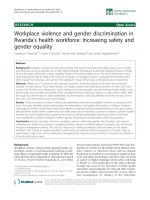
© 2011 Aslam and Lee ; licensee Springer.
This is an open access article distributed under the terms of the Creative Commons Attribution License ( />which permits unrestricted use, distribution, and reproduction in any medium, provided the original work is properly cited.
Fair, efficient, and power-optimized spectrum sharing scheme for
cognitive radio networks
Saleem Aslam and Kyung Geun Lee
*
Department of Information and Communication Engineering, Sejong
University, Seoul, Republic of Korea
*
Corresponding author:
Email address:
SA:
Abstract
The cognitive radio network (CRN) is a promising solution to the problem
of spectrum scarcity. To achieve efficient spectrum utilization, cognitive
radio requires a robust spectrum sensing and spectrum sharing scheme.
Therefore, spectrum sharing scheme plays a key role in achieving the
optimal utilization of the available spectrum. The spectrum sharing in CRN
is more challenging than traditional wireless network. The main factors
besides throughput and fairness which need to be addressed in spectrum
sharing of CRN are primary user (PU) activity, transmission power, and
variations in the radio environment. In this article, we propose fair, efficient,
and power-optimized (FEPO) spectrum sharing scheme that will incorporate
all critical factors mentioned above to maximize the spectrum utilization.
Simulation results show that FEPO scheme outperforms in terms of
transmission power by reducing the number of retransmissions and
guarantees required level of throughput and fairness. Moreover, periodic
monitoring helps to reduce the number of collisions with PUs.
Keywords: cognitive radio; spectrum sharing; primary user arrival activity;
licensed user; FEPO.
1. Introduction
Current static spectrum management schemes allocate fixed spectrum to
each existing wireless network. These schemes assign a block of the
spectrum band to a particular radio access-network standard, which is further
divided for spectrum allocations into individual operators of this access
technology. However, in recent years, wireless network technology grows
exponentially especially in the domain of low-cost wireless applications that
utilize the unlicensed spectrum bands. These growing applications have
raised the issue of spectrum scarcity for upcoming wireless services and
stirred the researchers to find new techniques for the efficient utilization of
the available spectrum. On the other side of the picture, the Federal
Communication Commission has reported that existing spectrum utilization
is very sparse at any given time and space [1, 2] as shown in Figure 1a.
It shows the variations in power spectral density (PSD) across the radio
spectrum from 0 to 6 GHz. Although there is a dense spectrum utilization
from 0 to 2 GHz yet there is a very sporadic spectrum utilization between 3
and 6 GHz. To deal with the problem of the inefficient spectrum utilization,
a new concept is evolved called dynamic spectrum access (DSA) or
opportunistic spectrum sharing (OSS) [1–3]. The DSA employs cognitive
radio (CR), a potential technology to reform the mechanism of spectrum
utilization. The DSA architecture consists of two main entities: licensed user
(LU) or primary user (PU), which has the legal rights to use the spectrum
and CR user or secondary user (SU); CR has temporal rights to utilize the
spectrum band of PUs on a negotiation basis. For example, in Figure 1b,
there are five PUs and four SUs operating in a cell with single active PU at a
given instant.
To avoid harmful interference with PU and to maximize efficiency of the
spectrum utilization, CR should periodically sense the radio environment
and opportunistically accesses the spectrum hole by dynamically adjusting
its transmission parameters like power level, modulation scheme, and coding
scheme. There are four major stages of the CR: (1) spectrum sensing, (2)
spectrum management, (3) spectrum sharing, and (4) spectrum mobility [3].
The prime objective of CR is the reliable detection and the optimal sharing
of spectrum holes among CR users.
Sharing schemes provides a way for spectrum allocation and multiplexing at
the data packet level. Moreover, congestion and admission control
mechanisms are directly dependent on sharing schemes. Many sharing
schemes capable of ensuring required level of QoS in wireless networks
have been proposed in the literature. However, these schemes cannot be
directly applied to cognitive radio network (CRN) because of the variation in
the capacity and quality of wireless channels across space and time and PU
arrival activity. Currently, it is an urgent need to develop new spectrum
sharing schemes at medium access control (MAC) layer for providing
required level of QoS and operate under tolerable interference limit.
Moreover, it is also desirable that the sharing scheme keeps track of the
changes occur in the condition and capacity of available wireless channels.
Among all other technical issues need to be addressed, spectrum sharing is
one of the important issue. In this article, we propose a robust spectrum
sharing scheme that will consider all important factors discussed earlier and
allocates the available sensed spectrum holes among competing CR users in
an optimal way.
The main contributions of this article are summarized as follows:
(i) We formulate the problem of spectrum sharing in a centralized intra CRN
using a slotted structure and considering all relevant metrics and
requirements of both SU and network. We provide an in-depth analysis of
existing spectrum sharing mechanisms and challenges faced in designing
such schemes. This is valuable for future research in this direction.
(ii) We propose a framework for dynamic spectrum sharing in CRN, which
incorporates the PU activity as well as changes occurring in the channels due
to the fluctuating behavior of the available spectrum in time and apace. To
provide a required level of throughput and maximum fairness to the
competing CR users, an optimized spectrum sharing strategy is introduced.
(iii) We propose a dynamic framing process at MAC layer, which makes
variable size frames depending upon the quality of channel.
(iv) Finally, we compare our proposed scheme with the MMF scheme given
in [4] in terms of power consumption to serve the CR users.
The rest of this article is organized as follows. Section 2 briefly presents the
previous study related to the spectrum sharing. Section 3 describes the
problem formulation process. In Section 4, the impact of PU activity is
discussed. The algorithm of the proposed scheme is discussed in Section 5.
Simulation results are demonstrated in Section 6. Finally, Section 7 covers
the conclusion of the article.
2. Related study
Most of the ongoing research in CRN is focused either on physical or MAC
layer. The basic aim of the CRN is to provide a way for the efficient
utilization of the existing spectrum [5–7]. The CR finds vacant spaces in the
licensed band called spectrum holes for opportunistic access [3]. The CRN
employs the sensing scheme to detect the presence or absence of the PUs.
Spectrum sensing schemes either detector the primary transmitter or receiver.
These schemes can also be classified as local or cooperative [3, 8, 9]. In the
local spectrum sensing each CR individually decides about the presence of
PU, whereas in the cooperative spectrum sensing multiple CR users
collectively decide about the presences of PUs on the particular spectrum
band. After locating the pool of spectrum holes, these are shared among CR
users. In [10], spectrum allocation algorithm is described based on the call
request control mechanism. The probability of call blocking is reduced
significantly because of the call request control mechanism. In [11], another
spectrum allocation algorithm is proposed for multi-user OFDM system to
maximize the overall capacity of the system. The proposed multi-user
algorithm provides better results in terms of capacity and fairness, but it is
limited to fully connected networks. A survey of the spectrum sharing
scheme in the CRN is presented in [12]. The authors have classified the
sharing schemes in three major classes of open, hierarchical, and dynamic
exclusive.
The advantages and challenges of each model are also discussed. In [13], the
authors present a comprehensive analysis and description on MAC protocols
for CRN. It explains the issues related to spectrum sensing, and latest
challenges at physical and MAC layers are also discussed in detail. The
author categorizes the MAC protocol in three main classes of random access,
time slotted, and hybrid protocols. In [14], the authors classify the sharing
schemes as centralized or distributive. In the centralized approach, a central
entity called a spectrum server or a spectrum broker, which is responsible for
sharing the available spectrum band among the CR users while in the
distributive method, each CR user participates in the sharing decision. They
exchange the information about the sensed spectrum and then collectively
share the spectrum among them according to their requirement. Another
classification based on architecture is presented in [15] where the sharing
schemes are classified as underlay or overlay. The underlay model seems to
be the best case as far as the CR operates under the interference level with
the PUs but it requires a complex hardware system. In [4, 16–18], various
centralized spectrum allocation schemes are proposed. In these schemes,
each CR user exchange control-information (CI) with the central server to
compete for sensed spectrum holes. The CI contains the sensed information,
synchronization information, and power level. Based on this exchanged
information, the spectrum server forms an optimal schedule for sharing the
spectrum holes among competing CR users. Other random access protocols
such as ALOHA and CSMA are presented in [19–21]. The authors propose
and simulate a system for the sharing of spectrum holes among CR users,
but these techniques are limited to the sharing of a single channel.
In [22] a spectrum sharing scheme based on the interference and power
control mechanism is proposed. The author introduces a variable rate and
power allocation scheme where each CR user on different channels has the
different amount of transmission power and data rate. The author utilizes
multilevel quadrature amplitude modulation to achieve throughput efficiency.
The concept of soft sensing information is introduced to get the information
about the PU activity and channel state information with respect to the
quality of channels. This scheme allocates the available channels under the
constraints of bit error rate, and averages transmit power. Although it is an
optimal scheme in terms of throughput, but it lacks in providing fairness
among CR users that is also an important factor for an optimized sharing
scheme.
The sharing schemes in CRN differ from the traditional cellular networks
channel sharing techniques because of the capricious nature of the spectrum
band in space, time, and quality. This becomes even more challenging if we
consider the arrival activity of the PUs as well. Most of the research efforts
in CRN are focused to find a way to cater with the interference problem with
PUs. There are two main methodologies to deal with the problem of
interference with the PUs. In first approach, a predictor forecasts the idle
time for the available channels [23–26]. In second approach, interference
can be avoided by taking on the fly channel eviction decision. This will
degrade the QoS for the SU, but it requires simplified structure as compared
to the former approach. In this article, we adopt the latter approach to avoid
the interference with the PUs in a centralized intra CRN.
3. Problem formulation
In this section, we present the methodology for the formulation of our
problem. First, we present the network model, and then proposed the
framework of our system. We also present the frame format that we have
considered for our system.
3.1 Network model
We consider a network with p = 1, 2, 3,…,P PUs and c = 1, 2, 3, 4, ,C CR
users operating in similar pattern as shown in Figure 1. Each CR user
performs sensing operation on n = 1, 2, 3,…,N primary channels of same cell
and forward this measurement to the central entity known as CR base station.
The primary channel can be modeled as an independent continuous-time
Markov process [27]. The transmission on nth channel for CR user c using
can be modeled using the Markov process as
)(tS
c
n
. The
0)( =tS
c
n
represents
the idle state, whereas
1)( =tS
c
n
indicates the busy state of channel. The CR
can transmit only during the idle state of the channel. We assume the slotted
structure for the CR transmission with slot length
λ
as shown in Figure 2.
The slot length
λ
is divided into three sub-slots. The symbol
τ
indicates
the sensing time consumed by a particular CR user,
ε
represents the
channel eviction time period, and t
d
represents data transmission period.
Mathematically, the slot length is
d
t
+
+
=
ε
τ
λ
(1)
ε
τ
λ
−
−
=
d
t
(2)
t
d
<<
<<
τ
ε
(3)
We assume that the channel eviction time is very small as compared to the
sensing time while the actual data transmission time is significantly larger
than the sensing time for a given time slot as shown in Figure 3. Moreover,
the allocation is performed after every time slot, and we assume that the
environment remains same for the duration of a given time slot.
3.2. The proposed framework
Monitoring the PU activity over channels helps significantly to reduce
interference with the PUs by vacating/evicting the channel. Figure 3
represents the proposed framework design for fair, efficient, and power
optimized (FEPO) scheme. The general steps can be listed as follows.
Step 1: The PU arrival monitor (PAM) block gathers the statistics about the
arrival of PUs on different frequency channels through the spectrum sensing.
Step 2: The PAM analyzes the current spectrum sensing results and sets the
value of the channel status flag (csf) for each currently in use frequency
channel. If the PU arrives on the same channel, then PAM sets csf = 1 for
that particular channel.
Step 3: The eviction controller (EC) block observes the csf flags of different
channels and preempts/evicts CR users accordingly. For example, if csf of a
particular channel is set to 1, then EC triggers the eviction of CR user from
that channel and at the same time informs the spectrum allocator (SA) about
this observation.
Step 4: The SA is the central entity that is responsible for sharing the
spectrum among CR users. The SA consists of four elements: (1) channel
quality indicator (CQI), (2) user database, (3) a first in first out (FIFO) queue,
and (4) a scheduler.
The CQI is responsible for measuring the quality of each unused frequency
channel by computing its signal-to-interference ratio (SIR). A user database
contains the information such as the identifier of CR users, the file size, and
the minimum data rate required for each CR user. The FIFO queue maintains
the list of CR users competing for channel availability. The spectrum
scheduler (SS) forms an optimal schedule by incorporating the observations
and calculations from different components within the spectrum allocator
with the prime objective of interference avoidance (eviction/silence) with
PU and transmission power reduction. We incorporate MMF scheduling
algorithm given in [4] to achieve global fairness among CR users. However,
if there is a need to vacate a channel on arrival of the PU, then SS will
update in-service users with the observation made by EC block.
Step 5: The CR users perform the transmission on the allocated channel and
then return to step 1 for sensing.
4. PU arrival activity
The CRN utilizes the spectrum band of PUs in an opportunistic manner on
the lease basis. From the view point of PUs, it is an important factor that
whenever PU needs a spectrum band, CR should vacate the channel to avoid
the interference and reduce the number of retransmissions.
Figure 4 represents the on–off activity of PUs on three different channels
that we consider for our simulation results. Initially, all three channels are in
idle state, i.e., 0)( =tS
c
n
∀
n and available for CR communication. A PU
arrives on channel 1 during the slot number 2, the status of channel gets
change from idle to busy state, i.e., 1)( =tS
c
n
for n = 1. During sensing
interval, CRs sense the arrival activity of PU and vacate the channel
immediately by performing channel eviction/vacation activity with the help
of EC block.
5. Algorithm
This section describes the algorithm that we have considered for our
approach. The details about the different notions and equation are also
discussed in this section.
Algorithm: FEPO spectrum sharing scheme
1. Input: n_user, n_ch, d
min
[i] and d
max
[i] for (i = 1, 2,3,…,C) n_user :number of CR user
2. user_serv0, Temp0, csf 0; Initialization
3. While (user_ser == 0) do
4. for n = 1 to N
5. If PU[n] == 1 PUs arrival
6. csf[n] = 1;
7. Temp = 0;
8. else
9. call CQI; calculate channels quality
10. call max-min fair; call max-min fair function
11. Temp = ch_data[n];
12. d_u[n] = d_u[n]- Temp; ch_data from max-min fair
13.
14. If user serve completely
15. n_user = n_user – 1;
16. bring new user;
17. end
18. end
19. if (n_user == 0) all user get served
20. user_serv = 1;
21. end
22. end
23. end
csf channel status flag
dmin minimum data rate requirement of CR
dmax max data file size of CR
d_u user data record variable
d_ch data rate on a channel
In the given algorithm of FEPO, csf represents the channel status flag of nth
channel in the given time slot. The CQI indicates the channel quality
identifier which expresses the quality of channels in terms of SIR. The
quality of free channels can be computed by the expression given in [4] as
∑
+
=
Ψ
≠ ni
ni
i
n
i
m
nnn
m
n
m
n
P
Gt
P
Gt
σ
2
(4)
where G
nn
is the channel gain, P
n
is the power by which CR transmits data
on channel n,
t
m
n
indicates the on–off pattern of a particular channel, and
2
n
σ
represents the noise variance. The subscript m indicates the transmission
mode. The terms with superscript i represent the effects of the interference
from other active CR users on the on the user operating on nth channel. As
the CR users increase in number, this factor gets increase and hence it will
decrease the overall SIR ratio. The data rate on the channels can be
calculated using the expression presented in [4] as
log(1 )
m m
n n
d = + Ψ
(5)
where d indicates the capacity of the channel n under certain transmission
mode m. For the simplicity, we consider the transmission mode in which all
the available channels are in active state in a given time slot. In order to
achieve fairness, we incorporate MMF scheme discussed in [4] which
allocate the equal data rate to all CR users. The proposed scheme also
maximizes the throughput while fulfills the minimum data rate requirement
(d
min
) of each CR user.
6. Results and analysis
In this section, we quantify the performance of our proposed scheme and
present simulation results. The simulation program is implemented in
Matlab. Although the simulation results are true for more general cases, yet
we perform analysis for some specific case to illustrate our outcomes. Our
approach is different from the previous studies in terms of taking into
account the sharing of the spectrum inconsistency because of irregular PU
activity and the changes occur in the radio environment. Moreover, we
compare the performance of our proposed technique with previous study in
terms of power consumption for the transmission of the CR user’s data file.
We also incorporate the dynamic framing process within the SA to make the
variable frame size. The parameters used for simulation are mentioned in the
Table 1.
6.1. Impact of selecting transmission the modes and variations in the channel
condition on data rate
Figure 5a shows the impact of selecting different transmission modes (TM)
on the throughput. The TM describes the on–off pattern of available
channels. Here, we consider only three channels with eight possible TMs
from 000 to 111 as defined in [4]. For example, for TM 001 channel 3 is the
best quality channel and has a data rate of 5.39 kbps, whereas channel 2 is
poor quality with data rate of 4.17 kbps for TM 010. The data rate reduces
significantly when two or more channels are active in a given time slot. This
reduction in data rate is because of the co-channel interference among CR
users. It can be seen that the co-channel interference is the maximum when
all the three channels are active under transmission mode 111, but it
provides fairness among CR users. As the CR is utilizing the spectrum band
of PU on lease basis and accessing opportunistically, there is a significant
variation in the channel condition (data rate) across time and frequency
during the transmission in each time slot. Figure 5b depicts the variation in
the data rate achieved for different time slots. As mentioned earlier, the
MMF scheme is used to provide same data rate on all available channels.
Hence, we plot the variations only for single radio channel in Figure 5b.
Initially, the data rate on the given channel is 1.82 kbps but data rate
decreases during second and third time slots. This decrease in data rate is
because of the poor channel condition. The data rate increases again to
1.85 kbps during time slot number 4 because of the significant improvement
in the channel condition as compared to the slot number 3. The maximum
data rate of 1.94 kbps and minimum data rate of 1.2 kbps are achieved
during time slot numbers 35 and 44, respectively. Hence, the achievable data
rate on a channel depends on its condition.
6.2. Channel eviction activity, sum rate, and channel sharing pattern
Figure 6 shows the channel eviction behavior and impact of PU activity on
the throughput of CR using the PU arrival pattern depicted in Figure 4. In
this case, we consider three CR users with different file sizes of 10, 5, and
10 kb, respectively. Initially, in the first time slot all primary channels are in
the idle state. Therefore, these channels can be used for CR communication.
In slot number 2, a PU arrives on channel 1. In this case, the PAM block sets
the csf = 1 for channel 1 and inform the SA about the arrival of PU at this
time slot. The SA evicts CR from channel 1 by triggering the channel
eviction mechanism. This may lead to slight degradation in CR user’s
throughput operating at the cost of interference avoidance. During time slot
numbers 3 and 4, a PU arrives on channel 2, the CR which is currently using
channel 2 immediately evicts the channel and switch to channel 1 for its
future communication. Lastly, if all the channels are being occupied by PUs
then the csf flags of all the channels are set to 1 and SA evicts/preempts all
CR users from transmission in order to avoid interference and reduce the
power used in retransmissions. This situation happens during slot number 5
as shown in Figure 4. There is a slight variation in the behavior of CR at
channels 2 and 3 during time slot number 7. This variation is due to the early
service effect (ESE). The ESE indicates that the remaining file size of CR
user is less than the data capacity of channel, and it is serviced fully at the
given time slot. The same argument is true for the small data usage on
channel 1 during time slot number 8.
The effect of channel eviction on the sum rate is illustrated in Table 2. The
sum rate is the sum of data rates achieved on all channels by all CR users.
For example, in current case, we consider three channels and the sum rate is
equal to the addition of available data rates on all channels. The results show
that the optimal sum rate is achieved for the case in which more channels are
available for CR users. The sum rate is maximum during slot number 1 as all
channels are being used for CR transmission. In this case, there is no activity
of PU on these channels. The sum rate declines significantly during slot
numbers 2, 3, and 4 because of the arrival of PU on the channels 1 and 2.
The channel sharing pattern of the proposed scheme is also shown in Table 2.
We consider six SUs with three transmitters and three receivers. We assume
that all SU transmitters are the same power, i.e., 30 dB. The file size and
user’s ID of SU are managed through a small database. The proposed
scheme selects the SUs from FIFO queue and assigns the available channel.
The framing is performed before transmission of the data, and the frames of
variable size are used depending upon the capacity of channels. For example,
channel 2 is assigned to the SU with ID 2 and SU
2
transmits fame of size
2.30 and 1.13 kb during slot numbers 1 and 2, respectively. Hence, OSA
maximizes the capacity utilization with variable frame size.
6.3. Effect of PU arrival on SU’s service time and throughput
Figure 7a,b shows the impact of PU arrival activity on the total service time
and throughput of SU. In this scenario, we show the outcomes for three
different file sizes and five SUs. The SUs have file size of 5, 10, and 15 kb.
Therefore; the total file size for each case is 25, 50, and 75 kb, respectively.
Figure 7a depicts the delay in the service time because of the arrival rate of
PU. In the first case, each SU has a file of 5 kb. All SUs get service in just
5 s. In this case, there is no PU activity on three available channels. The
service time increases in linear pattern with the increase of file size. It
becomes nearly double (5.9–11 s) when the total file size varies from 25 to
50 kb. Similarly, when we increase the total file size to 75 kb, the required
time to serve SUs becomes almost three times (16s). There is another
significant impact on service time because of the increase in the arrival
frequency of PU. For the arrival frequency equals to 20, there is an increase
of 110, 63, and 43% in the service time for the file size of 25, 50, and 75 kb,
respectively.
The effects of arrival activity of PU on small file size are slightly higher
since in certain time slot the SU may have less amount of remaining data
than the frame size. Figure 7b depicts the degradation in the SU’s throughput
with the increase in the arrival rate of PU. PU arrival rate is varied from 0 to
1. The fraction of throughput decreases linearly with the increase in the
arrival rate of the PU for larger file size. For small file size, there is a slight
variation in the behavior, this is because of the same reason given in
Figure 7a.
6 4. Comparison with MMF scheme
In this section, we compare our proposed FEPO scheme with the MMF
scheme in terms of transmission power. The periodic monitoring of PU
activity significantly reduces the transmission power.
In this case, we consider two different scenarios: (1) varying file size and (2)
varying number of retransmissions for the PU activity illustrated in Figure 4.
For simplification, we assume that system consumes 1 kW to transmit 1 kB
data file. In first scenario, the PU arrives six times on channels 1, 2, and 3,
respectively. The FEPO scheme utilizes the PAM block to monitor the
arrival activity of PU and does not transmit data when PU arrives on current
in use channel and save the significant amount of transmission power. We
simulate this scenario for different file sizes varying from 25 to 125 kb as
shown in Figure 8a. The FEPO transmits the same data file by consuming
10–40% lower power. For example, to transmit the file size of 25 kb MMF
requires 35 kW transmission power, whereas the FEPO scheme transmits the
same file with transmission power of 25 kW, which is significantly lower
power as compared to MMF scheme. Mathematically, the current scenario 1
for a given PU activity (see Figure 4) can be represented as follows.
ff
=
)(
ξ
(6a)
)()(
γ
β
ξ
+
+
=
ff
(6b)
where )( f
ξ
represents the power requirement for each scheme. The factor
f represents the power requirement of our proposed FEPO scheme. The
factor
γ
β
+
indicates the additional power factor for MMF scheme. The
β
factor has a constant value for a given PU activity. The
γ
factor is very
small as compared to the
β
factor, i.e.,
γ
<<
β
. In Figure 8a, the value of
β
factor is 10 and the values of
γ
factor are 1 and 2 for file size of 100 and
125 kb, respectively. The
γ
factor is zero for first three file sizes.
In second case, we show the comparison using file size of 75 kb and varying
the number of retransmissions. Each PU’s arrival requires a retransmission if
monitoring is not considered properly. The retransmissions are varied from 5
to 25, and we measure the power consumption for each scheme. It is clear
from the simulation results that MMF scheme consumes 11.5–58.5% extra
power for the transmission of same files having size of 25 and 125 kb,
respectively. Mathematically, the comparison of scenario 2 can be depicted
using the following equations
α
ξ
=
)(r (7a)
krr +=
αξ
)( (7b)
where )(r
ξ
represents the power requirement of each scheme. The proposed
FEPO scheme requires significantly lower power to transmit a given file.
However, the power requirement of MMF scheme increases linearly with the
increase in the number of retransmissions. The factor k is the slope factor
and r represents the number of retransmissions. In Figure 8b, the value of
α
factor is 75 kW, the factor r represents the number of retransmissions and k
is increasing factor, and its value is 1.82 for r = 20.