Sustainable Energy Harvesting Technologies Past Present and Future Part 3 pptx
Bạn đang xem bản rút gọn của tài liệu. Xem và tải ngay bản đầy đủ của tài liệu tại đây (1.04 MB, 20 trang )
Vibration Energy Harvesting:
Machinery Vibration, Human Movement and Flow Induced Vibration
29
shown in Fig. 4. In d
31
mode, a lateral force is applied in the direction perpendicular to the
polarization direction, an example of which is a bending beam that has electrodes on its top
and bottom surfaces as in Fig. 4(a). In d
33
mode, force applied is in the same direction as the
polarization direction, an example of which is a bending beam that has all electrodes on its
top surfaces as in Fig. 4(b). Although piezoelectric materials in d
31
mode normally have a
lower coupling coefficients than in d
33
mode, d
31
mode is more commonly used (Anton and
Sodano, 2007). This is because when a cantilever or a double-clamped beam (two typical
structures in vibration energy harvesters) bends, more lateral stress is produced than
vertical stress, which makes it easier to couple in d
31
mode.
(a) (b)
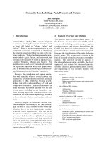
Fig. 4. Two types of piezoelectric energy harvesters (a) d
31
mode (b) d
33
mode
Piezoelectric energy harvesters have high output voltage but low current level. They have
simple structures, which makes them compatible with MEMS. However, most piezoelectric
materials have poor mechanical properties. Therefore, lifetime is a big concern for
piezoelectric energy harvesters. Furthermore, piezoelectric energy harvesters normally have
very high output impedance, which makes it difficult to couple with follow-on electronics
efficiently. Commonly used materials for piezoelectric energy harvesting are BaTiO
3
, PZT-
5A, PZT-5H, polyvinylidene fluoride (PVDF) (Anton & Sodano, 2007). In theory, with the
same dimensions, piezoelectric energy harvesters using PZT-5A has the most amount of
output power (Zhu & Beeby, 2011).
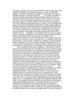
Fig. 5 compares normalized power density of some reported piezoelectric vibration energy
harvesters. It is found that micro-scaled piezoelectric energy harvesters have a greater
power density than macro-scale device. However, due to size constraints in micro-scaled
energy harvesters, the absolute amount of output power produced by the micro-scaled
energy harvesters is much lower than that produced by the macro-scaled generators.
Therefore, unless the piezoelectric energy harvesters are to be integrated into a
micromechanical or microelectronic system, macro-scaled piezoelectric generators are
preferred. Normalized power density of piezoelectric energy harvesters is about the same
level as that of electromagnetic energy harvesters.
Efforts have been made to increase output power of the piezoelectric energy harvesters.
Some methods include using more efficient piezoelectric materials (e.g. Macro-Fiber
Composite), using different piezoelectric configurations (e.g. mode 31 or mode 33),
optimizing power conditioning circuitry (Anton & Sodano, 2007), using different beam
shapes (Goldschmidtboeing & Woias, 2008) and using multilayer structures (Zhu et al.,
2010d).
Sustainable Energy Harvesting Technologies – Past, Present and Future
30
Fig. 5. Comparisons of normalized power density of some existing piezoelectric vibration
energy harvesters
2.3 Electrostatic vibration energy harvesters
Electrostatic energy harvesters are based on variable capacitors. There are two sets of
electrodes in the variable capacitor. One set of electrodes are fixed on the housing while the
other set of electrodes are attached to the inertial mass. Mechanical vibration drives the
movable electrodes to move with respect to the fixed electrodes, which changes the
capacitance. The capacitance varies between maximum and minimum value. If the charge
on the capacitor is constrained, charge will move from the capacitor to a storage device or to
the load as the capacitance decreases. Thus, mechanical energy is converted to electrical
energy. Electrostatic energy harvesters can be classified into three types as shown in Fig. 6,
i.e. In-Plane Overlap which varies the overlap area between electrodes, In-Plane Gap
Closing which varies the gap between electrodes and Out-of-Plane Gap which varies the
gap between two large electrode plates.
(a) (b) (c)
Fig. 6. Three types of electrostatic energy harvesters (a) In-Plane Overlap (b)In-Plane Gap
Closing (c) Out-of-Plane Gap Closing
Vibration Energy Harvesting:
Machinery Vibration, Human Movement and Flow Induced Vibration
31
Electrostatic energy harvesters have high output voltage level and low output current. As
they have variable capacitor structures that are commonly used in MEMS devices, it is easy
to integrate electrostatic energy harvesters with MEMS fabrication process. However,
mechanical constraints are needed in electrostatic energy harvesting. External voltage source
or pre-charged electrets is also necessary. Furthermore, electrostatic energy harvesters also
have high output impedance.
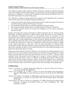
Fig. 7 compares normalized power density of some reported electrostatic vibration energy
harvesters. Normalized power density of electrostatic energy harvesters is much lower than
that of the other two types of vibration energy harvesters. However, dimensions of
electrostatic energy harvesters are normally small which can be easily integrated into chip-
level systems.
Fig. 7. Comparisons of normalized power density of some existing electrostatic vibration
energy harvesters
2.4 Tunable vibration energy harvesters
As mentioned earlier, most vibration energy harvesters are linear devices. Each device has
only one resonant frequency. When the ambient vibration frequency does not match the
resonant frequency, output of the energy harvester can be reduced significantly. One
potential method to overcome this drawback is to tune the resonant frequency of the energy
harvester so that it can match the ambient vibration frequency at all time.
Resonant frequency tuning can be classified into two types. One is called continuous tuning
which is defined as a tuning mechanism that is continuously applied even if the resonant
frequency matches the ambient vibration frequency. The other is called intermittent tuning
which is defined as a tuning mechanism that is only turned on when necessary. This tuning
mechanism only consumes power during the tuning operation and uses negligible energy
Sustainable Energy Harvesting Technologies – Past, Present and Future
32
once the resonant frequency is matched to the ambient vibration frequency (Zhu et al.,
2010a).
Resonant frequency tuning can be realized by mechanical or electrical methods. Realizations
of mechanical tuning include changing the dimensions of the structure, moving the centre of
gravity of proof mass and changing spring stiffness continuously or intermittently. Most
mechanical tuning methods are efficient in frequency tuning and suitable for in situ tuning,
i.e. tuning the frequency while the generator is in operation. However, extra systems and
energy are required to realize the tuning. Electrical methods typically adjust electrical loads
of the generator to tune the resonant frequency. This is much easier to implement. Closed-
loop control is necessary for both mechanical tuning and electrical tuning so that the
resonant frequency can match the vibration frequency at all times. As most of the existing
vibration energy harvesters are based on cantilever structures, only frequency tuning of
cantilever structures will be discussed in this section.
2.4.1 Variable dimensions
The spring constant of a resonator depends on its materials and dimensions. For a cantilever
with a mass at the free end, the resonant frequency, f
r
, is given by (Blevins, 2001):
()
c
r
mml
Ywh
f
24.04
2
1
3
3
+
=
π
(4)
where Y is Young’s modulus of the cantilever material; w, h and l are the width, thickness and
length of the cantilever, respectively. m is the inertial mass and m
c
is the mass of the cantilever.
The resonant frequency can be tuned by adjusting all these parameters. However, it is difficult
to change the width and thickness of a cantilever in practice. Only changing the length is
feasible. Furthermore, modifying length is suitable for intermittent tuning. The approach
requires an extra clamper besides the cantilever base clamp. This extra clamper can be released
and re-clamped in different locations for various resonant frequencies. There is no power
required to maintain the new resonant frequency. This approach has been patented (Gieras et
al., 2007). However, due to its complexity, there is few research reported on this method.
2.4.2 Variable centre of gravity of the inertial mass
The resonant frequency can be adjusted by moving the centre gravity of the inertial mass.
The ratio of the tuned frequency, f
r
’, to the original frequency, f
r
, is (Roylance & Angell,
1979):
3
2
2
21
148
26
3
1
'
234
2
+++
++
⋅=
rrr
rr
f
f
r
r
(5)
where r is the ratio of the distance between the centre of gravity and the end of the
cantilever to the length of the cantilever.
This approach was realized and reported by Wu et al (2008). The tunable energy harvester
consists of a piezoelectric cantilever with two inertial masses at the free end. One mass was
Vibration Energy Harvesting:
Machinery Vibration, Human Movement and Flow Induced Vibration
33
fixed to the cantilever while the other part can move with respect to the fixed mass. Centre
of gravity of the inertial mass could be adjusted by changing the position of the movable
mass. The resonant frequency of the device was successfully tuned between 180Hz and
130Hz. The output voltage dropped with increasing resonant frequency.
2.4.3 Variable spring stiffness
Another method to tune the resonant frequency is to apply an external force to change
stiffness of the spring. This tuning force can be electrostatic, piezoelectric, magnetic or other
mechanical forces. However, electrostatic force requires very high voltage. In addition,
spring stiffness can also be changed by thermal expansion but energy consumption in this
method is too high compared to power generated by vibration energy harvesters. Therefore,
these two methods are not suitable for frequency tuning in vibration energy harvesting. In
this section, only frequency tuning by piezoelectric, magnetic and direct forces is discussed.
Peters et al (2008) reported a tunable resonator suitable for vibration energy harvesting. The
resonant frequency tuning was realised by applying a force using piezoelectric actuators. A
piezoelectric actuator was used because piezoelectric materials can generate large forces
with low power consumption. The tuning voltage was chosen to be ±5V resulted in a
measured resonance shift of ±15% around the initial resonant frequency of 78 Hz, i.e. the
tuning range was from 66Hz to 89Hz. A closed-loop phase-shift control system was later
developed to achieve autonomous frequency tuning (Peters et al., 2009). Eichorn et al (2010)
presented a piezoelectric energy harvester with a self-tuning mechanism. The tuning system
contains a piezoelectric actuator to provide tuning force. The device has a tuning range
between 188Hz and 150Hz with actuator voltage from 2V to 50V. These are two examples of
continuous tuning.
An example of applying magnetic force to tune the resonant frequency was reported by Zhu
et al (2010b) who designed a tunable electromagnetic vibration energy harvester. Frequency
tuning was realised by applying an axial tensile magnetic force to a cantilever structure as
shown in Fig. 8.
Fig. 8. Frequency tuning by applying magnetic force (reproduced from (Zhu et al., 2010b))
The tuning force was provided by the attractive force between two tuning magnets with
opposite poles facing each other. One magnet was fixed at the free end of a cantilever while
the other was attached to an actuator and placed axially in line with the cantilever. The
Sustainable Energy Harvesting Technologies – Past, Present and Future
34
distance between the two tuning magnets was adjusted by the linear actuator. Thus, the
axial load on the cantilever, and hence the resonant frequency, was changed. The areas
where the two magnets face each other were curved to maintain a constant gap between
them over the amplitude range of the generator. The tuning range was from 67.6 to 98Hz by
changing the distance between two tuning magnets from 5 to 1.2mm. The tuning
mechanism does not affect the damping of the micro-generator over most of the tuning
range. However, when the tuning force became larger than the inertial force caused by
vibration, total damping increased and the output power was less than expected from
theory. A control system was designed for this energy harvester (Ayala-Garcia et al., 2009).
Energy consumed in resonant frequency tuning was provided by the energy harvester itself.
This is the first reported autonomous tunable vibration energy harvester that operates
exclusively on the energy harvester.
Resonant frequency of a vibration energy harvester can also be tuned by applying a direct
mechanical force (Leland and Wright, 2006). The energy harvester consisted of a double
clamped beam with a mass in the centre. The tuning force was compressive and was applied
using a micrometer at one end of the beam. The tuning range was from 200 to 250 Hz. It was
determined that a compressive axial force could reduce the resonance frequency of a
vibration energy harvester, but it also increased the total damping. The above two devices
are examples of intermittent tuning.
2.4.4 Variable electrical loads
All frequency tuning methods mentioned above are mechanical methods. Mechanical
methods generally have large tuning range. However, they require a load of energy to
realise. This is crucial to vibration energy harvesting where energy generated is quite
limited. Therefore, electrical tuning method is introduced. The basic principle of electrical
tuning is to change the electrical damping by adjusting electrical loads, which causes the
power spectrum of the generator to shift.
Charnegie (2007) presented a piezoelectric energy harvester based on a bimorph structure
and adjusted its resonant frequency by varying its load capacitance. The test results showed
that if one piezoelectric layer was used for frequency tuning while the other one was used
for energy harvesting, the resonant frequency can be tuned an average of 4 Hz with respect
to the original frequency of 350 Hz by adjusting the load capacitance from 0 to 10 mF. If both
layers were used for frequency tuning, the tuning range was an average of 6.5 Hz by
adjusting the same amount of load capacitance. However, output power was reduced if both
layers were used for frequency tuning while if only one layer was used for frequency
tuning, output power remained unchanged.
Another electrically tunable energy harvester was reported by Cammarano et al (2010). The
resonant frequency of the electromagnetic energy harvester was tuned by adjusting
electrical loads, i.e. resistive, capacitive and inductive loads. The tuning range is between
57.4 and 66.5Hz. However, output power varied with changes of electrical loads.
2.5 Vibration energy harvesters with wide bandwidth
The other solution to increase the operational frequency range of a vibration energy
harvester is to widen its bandwidth. Most common methods to widen the bandwidth
Vibration Energy Harvesting:
Machinery Vibration, Human Movement and Flow Induced Vibration
35
include using a generator array, using nonlinear and bi-stable structures. In this section,
details of these approaches will be covered.
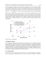
2.5.1 Generator array
A generator array consists of multiple small energy harvesters, each of which has different
dimensions and masses and hence different resonant frequencies. Thus, the assembled array
has a wide operational frequency range whilst the Q-factor does not decrease. The overall
power spectrum of a generator array is a combination of the power spectra of each small
generator as shown in Fig. 9. The frequency band of the generator is thus essentially
increased. The drawback of this approach is the added complexity in design and fabrication
of such array and the increased total volume of the device depending upon the number of
devices in the array.
Fig. 9. Frequency spectrum of a generator array
Sari et al (2008) reported a micromachined electromagnetic generator array with a wide
bandwidth. The generator consisted of a series of cantilevers with various lengths and hence
resonant frequencies. Cantilevers were carefully designed so that they had overlapping
frequency spectra with the peak powers at similar but different frequencies. This resulted in
a widened bandwidth as well as an increase in the overall output power. Coils were printed
on cantilevers while a large magnet was fixed in the middle of the cantilever array.
Experimentally, operational frequency range of this device is between 3.3 and 3.6 kHz
where continuous power of 0.5μW was generated.
A multifrequency piezoelectric generator intended for powering autonomous sensors from
background vibrations was presented by Ferrari et al (2008). The generator consisted of three
bimorph cantilevers with different masses and thus natural frequencies. Rectified outputs
were fed to a single storage capacitor. The generator was used to power a batteryless sensor
module that intermittently read the signal from a passive sensor and sent the measurement
information via RF transmission, forming an autonomous sensor system. Experimentally,
none of the cantilevers used alone was able to provide enough energy to operate the sensor
module at resonance while the generator array was able to power the sensor node within
wideband frequency vibrations.
Sustainable Energy Harvesting Technologies – Past, Present and Future
36
2.5.2 Nonlinear structures
The theory of vibration energy harvesting using nonlinear generators was investigated by
Ramlan (2009). Numerical and analytical showed that bandwidth of the nonlinear system
depends on the damping ratio, the nonlinearity and the input acceleration. Ideally, the
maximum amount of power harvested by a nonlinear system is the same as the maximum
power harvested by a linear system. There are two types of nonlinearity, i.e. hard
nonlinearity and soft nonlinearity as shown in Fig. 10. It is worth mentioning that output
power and bandwidth depend on the approaching direction of the vibration frequency to
the resonant frequency. For a hard nonlinearity, this approach will only produce an
improvement when approaching the device resonant frequency from a lower frequency. For
a soft nonlinearity, this approach will only produce an improvement when approaching the
device resonant frequency from a higher frequency. It is unlikely that these conditions can
be guaranteed in real application, which makes this method very application dependent.
Fig. 10. Soft and hard Nonlinearity
Most reported nonlinear vibration energy harvester is realized by using a magnetic spring.
Burrows et al (2007, 2008) reported a nonlinear energy harvester consisting of a cantilever
spring with the non-linearity caused by the addition of magnetic reluctance forces. The
device had a flux concentrator which guided the magnetic flux through the coil. The
reluctance force between the magnets and the flux concentrator resulted in non-linearity. It
was found experimentally that the harvester had a wider bandwidth during an up-sweep,
i.e. when the excitation frequency was gradually increased while the bandwidth was much
narrower during a down-sweep, i.e. when the excitation frequency was gradually
decreased. This is an example of hard nonlinearity.
Another example of nonlinear vibration energy harvester is a tunable electromagnetic
vibration energy harvester with a magnetic spring, which combined a manual tuning
mechanism with the non-linear structure (Spreemann et al., 2006). This device had a rotary
suspension and magnets as nonlinear springs. It was found in the test that the bandwidth of
the device increased as magnetic force became larger, i.e. non-linearity increased.
A numerical analysis of nonlinear vibration energy harvesters was recently reported
(Nguyen & Halvorsen, 2010). Analytical results showed that soft nonlinear energy
harvesters have better performance than hard nonlinear energy harvesters. This is yet to be
verified by experiments.
Vibration Energy Harvesting:
Machinery Vibration, Human Movement and Flow Induced Vibration
37
2.5.3 Bi-stable structures
Ramlan (2009) also studied bi-stable structures for energy harvesting (also termed the snap-
through mechanism). Analysis revealed that the amount of power harvested by a bistable
device is 4/π greater than that by the tuned linear device as the device produces a
squarewave output for a given sinusoidal input. Numerical results also showed that more
power is harvested by the mechanism if the excitation frequency is much less than the
resonant frequency. Bi-stable devices also have the potential to cope with the mismatch
between the resonant frequency and the vibration frequency.
Ferrari et al (2009) reported a nonlinear generator that exploits stochastic resonance with
white-noise excitation. A piezoelectric beam converter was coupled to permanent magnets
creating a bi-stable system bouncing between two stable states in response to random
excitation. Under proper conditions, this significantly improved energy harvesting from
wide-spectrum vibrations. The generator was realized by screen printing low-curing-
temperature lead zirconate titanate (PZT) films on steel cantilevers and excited with white-
noise vibrations. Experimental results showed that the performances of the converter in
terms of output voltage at parity of mechanical excitation were markedly improved.
Mann et al (2010) investigated a nonlinear energy harvester that used magnetic interactions
to create an inertial generator with a bistable potential well. The motivating hypothesis for
this work was that nonlinear behavior could be used to improve the performance of an
energy harvester by broadening its frequency response. Theoretical investigations studied
the harvester’s response when directly powering an electrical load. Both theoretical and
experimental tests showed that the potential well escape phenomenon can be used to
broaden the frequency response of an energy harvester.
Erturk et al (2009) introduced a piezomagnetoelastic device for substantial enhancement of
piezoelectric vibration energy harvesting. Electromechanical equations describing the
nonlinear system were given along with theoretical simulations. Experimental performance
of the piezomagnetoelastic generator exhibited qualitative agreement with the theory,
yielding large-amplitude periodic oscillations for excitations over a frequency range.
Comparisons were presented against the conventional case without magnetic buckling and
superiority of the piezomagnetoelastic structure as a broadband electric generator was
proven. The piezomagnetoelastic generator resulted in a 200% increase in the open-circuit
voltage amplitude (hence promising an 800% increase in the power amplitude).
2.6 Summary
Eq. 3 gives a good guideline in designing vibration energy harvester. The maximum power
converted from the mechanical domain to the electrical domain is proportional to the mass
and vibration acceleration squared and inversely proportional to the resonant frequency as
well as total damping. This means that more power can be extracted if the inertial mass is
increased or energy harvesters can work in the environment where the vibration level is
high. For a fixed resonant frequency, the generator has to be designed to make the
mechanical damping as low as possible. For an energy harvester with constant damping, the
generated electrical power drops with an increase of the resonant frequency.
Sustainable Energy Harvesting Technologies – Past, Present and Future
38
However, as vibration energy harvesters are usually designed to have a high Q-factor for
better performance, the generated power drops dramatically if resonant frequencies and
ambient vibration frequencies do not match. Therefore, most reported generators are
designed to work only at one particular frequency. For applications such as moving
vehicles, human movement and wind induced vibration where the frequency of ambient
vibration changes periodically, the efficiency of energy harvesters with one fixed resonant
frequency is significantly reduced since the generator will not always be at resonance. This
drawback must be overcome if vibration energy harvesters are to be widely applicable in
powering wireless systems.
Tuning the resonant frequency of a vibration energy harvester is a possible way to increase
its operational frequency range. It requires a certain mechanism to periodically adjust the
resonant frequency so that it matches the frequency of ambient vibration at all times.
The suitability of different tuning approaches will depend upon the application, but in
general terms the key factors for evaluating a tuning mechanism for adjusting the resonant
frequency of vibration energy harvesters are as follows. First, energy consumed by the
tuning mechanism must not exceed the energy generated. Second, tuning range should be
large enough for certain applications. Third, tuning mechanism should achieve a suitable
degree of frequency resolution. Last but not least, tuning mechanism should have as little
effect on total damping as possible. Furthermore, intermittent tuning is preferred over
continuous tuning as it is only on when necessary and thus saves energy.
It is important to mention that efficiency of mechanical tuning methods depends largely on
the size of the structure. The smaller the resonator, the higher the efficiency of the tuning
mechanism. Efficiency of resonant frequency tuning by adjusting the electrical load depends
on electromechanical coupling. The better the coupling, the larger the tuning range.
Mechanical tuning methods normally provide large tuning range compared to electrical
tuning methods while electrical tuning methods require less energy than mechanical tuning
methods.
Operational frequency range of a vibration energy harvester can be effectively widened by
designing an energy harvester array consisting of multiple small generators which work at
various frequencies. Thus, the assembled energy harvester has a wide operational frequency
range whilst the Q-factor does not decrease. However, this array must be designed carefully
so that individual harvesters do not affect each other, which makes it more complex to
design and fabricate. In addition, only a portion of individual harvesters contribute to
power output at a particular source frequency. Therefore, this approach is not volume
efficient. Furthermore, non-linear energy harvesters and harvesters with bi-stable structures
are another two solutions to increase the operational frequency range of vibration energy
harvesters. They can improve performance of the generator at higher and lower frequency
bands relative to its resonant frequency, respectively. However, the mathematical modelling
of these energy harvesters is much more complicated than that of linear generators, which
increases the complexity in design and implementation. In addition, there is hysteresis in
non-linear energy harvesters. Performance during down-sweep (or up-sweep) can be worse
than that during up-sweep (or down-sweep) or worse than the linear region depending on
sweep direction. Therefore, when designing nonlinear energy harvesters, this must be taken
into consideration. In contrast, energy harvesters with bi-stable structures are less frequency
dependent, which makes it a potentially better solution.
Vibration Energy Harvesting:
Machinery Vibration, Human Movement and Flow Induced Vibration
39
In summary, some most practical methods to increase the operation frequency range for
vibration energy harvesting include:
• changing spring stiffness intermittently (preferred) or continuously;
• adjusting electrical loads;
• using generator arrays;
• employing non-linear and bi-stable structures.
3. Energy harvesting from human movement
The human body contains huge amount of energy. The kinetic energy from human
movement can be harvested and converted to electrical energy. The electrical energy
produced can be used to power other wearable electronics, for example, a watch and a heart
rate monitor. It can also be used to charge portable electronics, such as mobile phones, mp3
players or even laptops. Researches have been done to study movement of different parts of
a human body. It was found that upper human body produces movement with frequencies
less than 10Hz while frequencies of movement from lower human body are between 10 and
30Hz (von Buren, 2006). The first prototype of the electronic device powered by human
movement is an electronic watch developed by SEIKO in 1986. Two years later, SEIKO
launched the world’s first commercially available watch, called AGS. Since then, more and
more human-powered electronic devices have come to the market and researches in this
area have drawn more attention (Romero et al., 2009). So far, two common types of human
energy harvesters are energy harvesting shoes and backpacks.
3.1 Shoes
Energy harvesters in shoes are based on either pressure of the human body on the shoe sole
or the kicking force during walking.
Kymissis et al (1998) studied energy harvesters mounted on sneakers that generated
electrical energy from the pressure on the shoe sole. Output power of three types of energy
harvesters was reported. The first energy harvesters had multilayer laminates of PVDF, the
second one contained a PZT unimorph and the third one was a rotary electromagnetic
generator. The PVDF and PZT elements were mounted between the removable insole and
rubber sole. The PVDF stack was in the front of the shoe while the PZT unimorph was at the
heel. The electromagnetic generator was installed under the heel. Experimentally, the three
generators produced average power of 1.8mW, 1.1mW and 230mW, respectively.
Carroll and Duffy (2005) reported a sliding electromagnet generator placed inside the shoe
sole for energy harvesting. This device extracted electrical energy from the kicking force
during walking. The generator consists of a set of three coils with magnets moving inside
the coils. Experimentally, this generator produced up to 8.5mW of power at 5Hz. A smaller
set of three generators was also presented. This set delivered up to 230μW of power at 5Hz.
3.2 Backpacks
There are also two types of energy harvesting from backpacks. One utilises linear vertical
movement of the backpacks to generate electrical energy and the other is based on stress on
the strips of the backpacks.
Sustainable Energy Harvesting Technologies – Past, Present and Future
40
Rome et al (2005) studied a backpack that converted kinetic energy from the vertical
movement of a backpack to electrical energy. The backpack consisted of a linear bearing and
a set of springs suspended the load relative to a frame and shoulder harness. The load could
move vertically relative to the frame. This relative motion was then converted to electrical
energy using a rotary electric generator with a rack and pinion. This system was
demonstrated to generate a maximum power of approximately 7.37W. Although the
backpack does generate significant power levels, the additional degree of freedom provided
to the load could impair the user’s dexterity and lead to increased fatigue.
Saha et al (2008) reported a nonlinear energy harvester with guided magnetic spring for
energy harvesting from human movement. The average measured maximum load powers
of the generator without top fixed magnets were 0.95mW and 2.46mW during walking and
slow running condition, respectively.
Energy harvesting from a backpack with piezoelectric strips was reported by Granstrom et
al (2007). The traditional strap of the backpack was replaced by one made of PVDF. PVDF
was chosen due to its high flexibility and strength. In the test, a preload of around 40N was
applied to the straps to simulate the static weight in the backpack while a 20N sine wave
with a frequency of 5Hz was applied to simulate the alternating load in the backpack. Strips
with PVDF of 28µm and 52µm were compared. Maximum power generated in these two
strips was 3.75mW and 1.36mW, respectively.
Another backpack targeted straps as locations for piezoelectric generators was reported by
Feenstra et al (2008). A piezoelectric stack was placed in series with the backpack straps. The
tension force that the piezoelectric stack receives from the cyclic loading is mechanically
amplified and converted into a compressive load. The average power output measured
when walking on a treadmill with a 40lb load was reported as 176μW. The maximum power
output for the device was expected to be 400μW.
3.3 Summary
Energy harvesting from human movement is quite different from energy harvesting from
machinery vibration due to some special characters. First, human movement has low
frequency (<30Hz) and large displacement (several mm or cm). Second, human movement
is not sinusoidal. It is normally random. Therefore, resonant energy harvesters that are
widely used in energy harvesting from machinery are not suitable for this application. Last
but not least, energy harvesters to be worn on human body should have reasonable size and
weight so that they will not affect normal human activity. Table 1 summarizes some
reported energy harvesters from human movement.
4. Energy harvesting from flow induced vibrations
The turbine generator is the most mature method for flow energy harvesting. However, the
efficiency of conventional turbines reduces with their sizes due to the increased effect of
friction losses in the bearings and the reduced surface area of the blades. Furthermore,
rotating components such as bearings suffer from fatigue and wear, especially when
miniaturised. These drawbacks of turbine generators urges emergence of a new area in
energy harvesting, i.e. energy harvesting from flow induced vibration. The flow here
Vibration Energy Harvesting:
Machinery Vibration, Human Movement and Flow Induced Vibration
41
Generator type Position Operational principle Output power (mW)
PVDF laminates front of the shoe
Pressure
1.8
PZT unimorph heel 1.1
electromagnetic heel 230
electromagnetic heel Kicking force 8.5
nonlinear
backpack
Walking 0.95
Running 2.46
PVDF strip
Preload: 40N
20N sine wave@5Hz
3.75
1.36
Piezoelectric stack Walking 0.176
Table 1. Comparisons of some existing energy harvesters from human movement
includes both liquid flow and air flow. There are three main types of energy harvester of this
kind. They are energy harvesting from vortex-induced vibration (VIV), flutter energy
harvesters and energy harvesters with Helmholtz resonators. Principles and reported
devices will be presented in this section.
4.1 Energy harvesting from vortex-induced vibrations
Flow-induced vibration, as a discipline, is very important in our daily life, especially in civil
engineering. Generally, scientists try to avoid flow-induced vibration in buildings and
structures to reduce possible damage. Recently, such vibration has been investigated as an
energy source that can be used to generate electrical energy. Two types of flow-induced
vibration are studied so far: vortex-induced vibration and flutter.
4.1.1 Principles
When a fluid flows toward the leading edge of a bluff body, the pressure in the fluid rises
from the free steam pressure to the stagnation pressure. When the flow speed is low, i.e. the
Reynolds number is low, pressure on both sides of the bluff body remains symmetric and no
turbulence appears. When the flow speed is increased to a critical value, pressure on both
sides of the bluff body becomes unstable, which causes a regular pattern of vortices, called
vortex street or Kármán vortex street as shown in Fig. 11. Certain transduction mechanisms
can be employed where vortices happen and thus energy can be extracted. Sanchez-Sanz et
al (2009) studied the feasibility of energy harvesting based on the Kármán vortex street and
proposed several design rules of such micro-resonator. This method is suitable both air flow
and liquid flow.
Flutter is a self-feeding vibration where aerodynamic forces on an object couple with a
structure's natural mode of vibration to produce rapid periodic motion. Flutter can occur in
any object within a strong fluid flow, under the conditions that a positive feedback occurs
between the structure's natural vibration and the aerodynamic forces. Flutter can be very
disastrous. The worst example of flutter is the disaster of Tacoma Narrows Bridge that
Sustainable Energy Harvesting Technologies – Past, Present and Future
42
collapsed due to the aeroelastic flutter. However, such vibrant movement makes it an ideal
source for energy harvesting. This method is normally only suitable for air flow as damping
in liquid flow is very high, which makes flutter less likely to happen.
Fig. 11. An example of Kármán vortex street
4.1.2 Energy harvesting in liquid flow
The most famous energy harvester based on Kármán vortex street is the ‘Energy Harvesting
Eel’ (Allen & Smits, 2001; Taylor et al., 2001). Fig. 12 shows a schematic of the device. The
‘eel’ was a flexible membrane with PVDF on it. It is riveted a certain distance away behind a
fixed bluff body. The vortices behind the bluff body caused the ‘eel’ to swing from one end
to the other. Electrical energy can then be generated by the PVDF from such movement.
However, no detailed test results were reported.
Fig. 12. Schematic of the ‘Energy Harvesting Eel’ (top view)
Wang and Pham (2011a) reported a small scale water flow energy harvester based on
Kármán vortex street. The energy harvester had a flexible diaphragm on which a
piezoelectric film (PVDF) was attached. There was a chamber below the diaphragm where
the water flows. A bluff body iwas placed at the centre of the chamber. When the water flew
past the bluff body, vortex street occurred. The diaphragm moved up and down with the
Vibration Energy Harvesting:
Machinery Vibration, Human Movement and Flow Induced Vibration
43
vortices. The movement of the diaphragm bent the piezoelectric film and thus generated
electrical energy. Experimental results showed that an open circuit output voltage of 0.12V
pp
and an instantaneous output power of 0.7nW were generated when the pressure oscillated
with amplitude of 0.3kPa and a frequency of 52Hz. Its active volume was 50mm × 26mm ×
15mm. The active volume is defined as the product of the area of the diaphragm times the
thickness of the device.
Similar devices without the bluff body were also studied by Wang et al (2010a, 2010b,
2011b). Both piezoelectric and electromagnetic transducers were used. Table 2 lists their test
results.
Transducer
Output
power
(µW)
Open
circuit
voltage (V)
Flow
pressure
(Pa)
Flow
frequency
(Hz)
Active volume
(mm × mm ×
mm)
Electromagnetic
(Wang, 2010a)
0.4 0.01 254 30 900 × 600 × 400
Piezoelectric
(Wang, 2011b)
0.45×10
-3
0.072 20.8k 45 23 × 15 × 10
Piezoelectric
(Wang, 2010b)
0.2 2.2 1196 26 50 × 30 × 7
Table 2. Comparison of Wang’s work
Fig. 13. Principle of VIVACE
Another type of energy harvesters in water based on Kármán vortex street is called Vortex
Induced Vibration for Aquatic Clean Energy (VIVACE) (
Bernitsas, 2006). The principle of
this energy harvester is slightly different from that of the ones mentioned above. Instead of
using the vortices created by a fixed bluff body, this energy harvester uses movement of the
bluff body caused by the vortices it produces itself to generate power. When a flow passes a
mobile bluff body, vortices are formed. The formation of a vortex alternately above and
Sustainable Energy Harvesting Technologies – Past, Present and Future
44
below the cylindrical bluff body forces an alternating vertical motion of the cylinder, the
energy of which can be extracted (as shown in Fig. 13.). Note that the bluff body was
designed to be restricted to have only one degree of freedom. Electromagnetic transducer
was used to generator electrical energy. Multiple cylinders can be used to form arrays
depending on applications.
Such devices are currently available only in large scales. Six different scales of VIVACE with
power lever between 50kW and 1GW were reported so far. More work needs to be done to
minimize it so that it can be used to power wireless sensor nodes. Barrero-Gil et al (2010)
published a model for such energy harvesting method. Several design rules were
summarized. Furthermore, the authors concluded that it is fairly straightforward to
minimize such devices.
4.1.3 Energy harvesting in airflow
One method of energy harvesting based on Kármán vortex street, called flapping-leaf, has
been reported by Li and Lipson (2011). The flapping-leaf energy harvester had the same
principle as the ‘energy harvesting eel’ while it was only designed to work in airflow. The
device consisted of a PVDF cantilever with one end clamped on a bluff body and the other
end connected to a triangular plastic leaf. When the airflow passed the bluff body, the
vortices produced fluctuated the leaf and thus the PVDF cantilever to produce electrical
energy. The energy harvester generated a maximum output power of 17µW under the wind
of 6.5m·s
-1
. Dimensions of the PVDF cantilever was 73mm × 16mm × 40μm.
Dunnmon et al (2011) reported a piezoelectric aeroelastic energy harvester. It consists of a
flexible plate with piezoelectric laminates which was placed behind a bluff body. It was
excited by a uniform axial flow field in a manner analogous to a flapping flag such that the
system delivered power to an electrical impedance load. In this case, the bluff body was in
the shape of a standard NACA 0015 rather than a cylinder. The beam was made of 2024-T6
aluminium and an off-the-shelf piezoelectric patch was mounted close to the clamped end of
the beam in the centre along the width of the beam. Experimental results showed that a RMS
output power of 2.5mW can be derived under a wind of 27m·s
-1
. The generator was
estimated to have an efficiency of 17%. The plate had dimensions of 310mm × 101mm ×
0.39mm and the bluff body has a length of 550mm. Dimensions of the piezoelectric laminate
were 25.4mm × 20.3mm × 0.25mm.
Jung and Lee (2011) recently presented a similar electromagnetic energy harvester as
VIVACE. Instead of operating under water, this device was designed to work under air
flow. In addition, this device had a fixed cylinder bluff body in front of the mobile cylinder.
These two cylinders had the same dimensions. It was found that the displacement of the
mobile cylinder largely depends on the distance between the two cylinders and the
maximum displacement can be achieved when this distance was between three and six
times of the cylinder diameter. In the experiments, a prototype device can produce an
average output power of 50-370mW under wind of 2.5-4.5 m·s
-1
. Both cylinders had a
diameter of 5cm and a length of 0.85m.
Zhu et al (2010c) presented a novel miniature wind generator for wireless sensing
applications. The generator consisted of a wing that was attached to a cantilever spring
Vibration Energy Harvesting:
Machinery Vibration, Human Movement and Flow Induced Vibration
45
made of beryllium copper. The airflow over the wing caused the cantilever to bend upwards,
the degree of bending being a function of the lift force from the wing and the spring constant.
As the cantilever deflects downwards, the flow of air is reduced by the bluff body and the lift
force reduced causing the cantilever to spring back upwards. This exposes it to the full airflow
again and the cycle is repeated (as shown in Fig. 14). When the frequency of this movement
approaches the resonant frequency of the structure, the wing has the maximum displacement.
A permanent magnet was fixed on the wing while a coil was attached to the base of the
generator. The movement of the wing caused the magnetic flux cutting the coil to change,
which generated electrical power. The proposed device has dimensions of 12cm × 8cm ×
6.5cm. It can start working at a wind speed as low as 2.5m·s
-1
when the generator produced an
output power of 470µW. This is sufficient for periodic sensing and wireless transmission.
When the wind speed was 5m·s
-1
, the output power reached 1.6mW.
Fig. 14. Principle of the energy harvester in (Zhu et al., 2010) (transducer is not shown)
4.2 Flutter energy harvesters
The first flapping wind generator was invented by Shawn Frayne and his team in 2004,
called Windbelt generator (Windbelt, 2004). The Windbelt generator uses a tensioned
membrane undergoing a flutter oscillation to extract energy from the wind as shown in Fig.
15. Magnets are attached to the end of the membrane. They move with the membrane and
are coupled with static coils to generate electricity. The company offer Windbelt generators
of different sizes. The smallest Windbelt generator has dimensions of 13cm × 3cm × 2.5cm.
Fig. 15. Windbelt: airflow is perpendicular to this page
Sustainable Energy Harvesting Technologies – Past, Present and Future
46
The minimum wind speed to make it work is 3m·s
-1
, where an output power less than
100μW was produced. The generator can produce output power of 0.2mW, 2mW and 5mW
under the wind of 3.5m·s
-1
, 5.5m·s
-1
and 7.5m·s
-1
respectively (Windbelt, 2004).
Kim et al (2009) reported a small-scale version of the Windbelt generator. The generator had
dimensions of 12mm × 12mm × 6mm. The generator was tested under the airflow with the
pressure of 50kPa. It produced a voltage output with the frequency of 530Hz and the
amplitude of 80mVpp.
Erturk et al (2010) investigated the concept of piezoaeroelasticity for energy harvesting. A
mathematical model was established and a prototype device was built to validate the model.
The generator had a 0.5m long airfoil vertically placed. Two PZT-5A piezoceramics were
attached onto the two ends of the airfoil. Under certain airflow, the airfoil flapped and
actuated the piezoceramics to produce electricity. An electrical power output of 10.7mW
was delivered to a 100 kΩ load at the linear flutter speed of 9.3m·s
-1
.
Li et al (2009, 2011) reported another type of flapping-leaf which works based on aeroelastic
flapping. The device had a PVDF cantilever with its width direction parallel to the air flow.
The leaf was placed to make the entire device like an ‘L’ shape as shown in Fig. 16. Different
PVDF cantilevers were compared in the test. It was found that the optimum device
generated a peak power of 615µW in the wind of 8m·s
-1
.
Fig. 16. Flapping-leaf based on aeroelastic flapping
St. Clair et al (2010) reported a micro generator using flow-induced self-excited oscillations.
The principle is similar to music-playing harmonicas that create tones via oscillations of
reeds when subjected to air blow. Output power between 0.1 and 0.8mW was obtained at
wind speeds ranging between 7.5 and 12.5m·s
-1
.
4.3 Energy harvesting with a Helmholtz resonator
4.3.1 Principles
A Helmholtz resonator is a gas-filled chamber with an open neck (as shown in Fig. 17), in
which a standard second-order (i.e. spring-mass) fluidic oscillation occurs. The air inside the
neck acts as the mass and the air inside the chamber acts as the spring. When air flows past
the opening, an oscillation wave occurs. Generally, the cavity has several resonance
Vibration Energy Harvesting:
Machinery Vibration, Human Movement and Flow Induced Vibration
47
frequencies, the lowest of which is the Helmholtz resonance. The Helmholtz resonant
frequency is given by:
2
H
vA
f
Vl
π
= (6)
where v is the speed of sound in a gas, A is the cross sectional area of the neck, l is the length
of the neck and V is the static volume of the cavity.
Fig. 17. Helmholtz resonator
4.3.2 Examples
Matova et al (2010) reported a device that had a packaged MEMS piezoelectric energy
harvester inside a Helmholtz resonator. It was found that packaged energy harvesters had
better performance than unpackaged energy harvesters as the package removes the viscous
influence of the air inside the Helmholtz cavity and ensure that only the oscillation excites
the energy harvester. Experimental results showed that the energy harvester generated a
maximum output power of 2µW at 309Hz under the airflow of 13m·s
-1
. Furthermore, it was
found that a major drawback of the Helmholtz resonator is its strong dependence of their
resonant frequency on the ambient temperature. This means that this kind of energy
harvesters can only be used in the environments with stable temperature or the energy
harvester must have a wide operational frequency range.
Kim et al (2009) presented a Helmholtz-resonator-based energy harvester with an
electromagnetic transducer. The device has a membrane with a magnet attached at the
bottom of the cavity. As the membrane oscillates due to the Helmholtz resonance, a static
coil is coupled with the moving magnet to generate electricity. Two energy harvesters were
fabricated and tested. The first one had dimensions of φ19mm × 5mm and a resonant
frequency of 1.4kHz. It generated an open circuit voltage of 4mV
pp
under the airflow of
0.2kPa (5m·s
-1
). The second device had dimensions of φ9mm × 3mm and a resonant
frequency of 4.1kHz. It generated an open circuit voltage of 15mV
pp
under the airflow of
1.6kPa.
Sustainable Energy Harvesting Technologies – Past, Present and Future
48
Liu et al (2008) demonstrated the development of an acoustic energy harvester using
Helmholtz resonator. It uses a piezoelectric diaphragm to extract energy. The diaphragm
consisted of a layer of 0.18mm-thick brass as the substrate and a layer of 0.11mm-thick
piezoceramics (APC 850). Experimental results showed an output power of about 30mW
was harvested for an incident sound pressure level of 160 dB with a flyback converter. The
cavity had dimensions of φ12.68mm × 16.4mm.
4.4 Summary
Among these three types of energy harvesters from flow induced vibration, energy
harvesters based on VIV and flapping energy harvesters are more suitable for practical
application due to their reasonable output power level. Existing energy harvesters with
Helmholtz resonators have very low output power and more work needs to be done to
make this approach practical. In addition, all piezoelectric flow energy harvesters use PVDF
as piezoelectric material due to its flexibility. However, piezoelectric coefficients of PVDF
are low compared to those of other piezoelectric materials. Flexible piezoelectric materials
with higher piezoelectric coefficients, for example Macro Fiber Composite (MFC), need to be
investigated to improve output power of piezoelectric flow energy harvesters.
5. Conclusions
A vibration energy harvester is an energy harvesting device that couples a certain
transduction mechanism to ambient vibration and converts mechanical energy to electrical
energy. Ambient vibration includes machinery vibration, human movement and flow
induced vibration.
For energy harvesting from machinery vibration, the most common solution is to design a
linear generator that converts kinetic energy to electrical energy using certain transduction
mechanisms, such as electromagnetic, piezoelectric and electrostatic transducers.
Electromagnetic energy harvesters have the highest power density among the three
transducers. However, performance of electromagnetic vibration energy harvesters reduces
a lot in micro scale, which makes it not suitable for MEMS applications. Piezoelectric energy
harvesters have the similar power density to the electromagnetic energy harvesters. They
have simple structures, which makes them easy to fabricate. Electrostatic energy harvesters
have the lowest power density of the three, but they are compatible with MEMS fabrication
process and easy to be integrated to chip-level systems.
The linear energy harvester produces a maximum output power when its resonant
frequency matches the ambient vibration frequency. Once these two frequencies do not
match, the output power drops significantly due to high Q-factor of the generator. Two
possible methods to overcome this drawback are tuning the resonant frequency of the
generator to match the ambient vibration frequency and widening bandwidth of vibration
energy harvesters.
The methods of tuning the resonant frequency include mechanical method and electrical
method. The mechanical tuning method requires a certain mechanism to change the
mechanical property of the structure of the generator to tune the resonant frequency. Thus,
it requires more energy to implement while it normally has a large tuning range.