Sustainable Energy Harvesting Technologies Past Present and Future Part 7 pdf
Bạn đang xem bản rút gọn của tài liệu. Xem và tải ngay bản đầy đủ của tài liệu tại đây (1.01 MB, 20 trang )
4
Modeling and Simulation of Thermoelectric
Energy Harvesting Processes
Piotr Dziurdzia
AGH University of Science and Technology in Cracow
Poland
1. Introduction
Thermoelectric modules are becoming more and more popular nowadays again as their
prices are going down and the new potential applications have appeared due to recent
developments in microelectronic and wireless technology. Not so long ago Peltier modules
were mainly used as thermoelectric coolers TECs, for example in thermal image generator
(De Baetselier et al., 1995a), thermoelectrically cooled radiation detectors (Anatychuk, 1995),
active heat sinks for cooling of microstructures and microprocessors (Dziurdzia & Kos,
2000), fiber optic laser packages (Redstall & Studd, 1995), special medical and laboratory
equipment for temperature regulation (Uemura, 1995), etc. Also in some niche applications,
thermoelectric modules working as thermoelectric generators TEGs have been used for
some time. Among others, the examples include a miniature nuclear battery for space
equipment (Penn, 1974) and remote power stations (McNaughton, 1995).
Fulfilment of the new paradigm Internet of Things (Luo et al., 2009) relating to the idea of
ubiquitous and pervasive computing as well as rapid development of wireless sensor
networks WSN technologies have attracted recently a great research attention of many R&D
teams working in the area of autonomous sources of energy (Paradiso & Starner, 2005),
(Joseph, 2005). Apart from light and vibrations, heat energy and thermoelectric conversion
are playing an important role in the field of energy harvesting or energy scavenging.
As a rule, thermoelectric generators suffer from relatively low conversion efficiency (not
exceeding 12%), so they are practically not applicable to large-scale systems, not to mention
power stations. On the other hand they seem to be promising solutions when they are used
to harvesting some waste heat coming from industry processes or central heating systems.
In recent years a lot of attention was paid to analyzing Peltier modules and efficiency of
thermal energy conversion into electrical one (Beeby & White, 2010), (Priya & Inman, 2009).
Now, many research teams are striving for development of complete autonomous devices
powering WSN nodes. Since low power integrated circuits, like microcontrollers,
transceivers and sensors, have been commonly available for several years the efforts are
focused nowadays especially on ambient energy scavenging and emerging technologies in
the field of ultra low voltage conversion, energy storing and efficient power management
(Salerno, 2010). There are solutions already reported, operating from extremely low voltages
Sustainable Energy Harvesting Technologies – Past, Present and Future
110
about tens of mV resulting from very small temperature gradients, equaling to single
Celsius degrees. In fact, some presented prototypes could be supplied from energy easily
available even from human body heat, for example a sensor application (Mateu et al., 2007)
and wristwatch (Kotanagi et al., 1999).
Lack of dedicated tools covering complex simulations of thermoelectric devices in both
thermal and electrical domains prompted many research teams into developing of original
models of Peltier elements facilitating analysis and design of thermoelectric coolers
(Lineykin & Ben-Yaakov, 2005), (Dziurdzia & Kos, 1999), (Wey, 2006) as well as
thermoegenerators (Chen et al., 2009), (Freunek et al., 2009).
The goal of this text is to show viability of modelling of complex phenomena occurring in
thermoelectric devices during energy harvesting as well as coupled simulations both
thermal and electrical processes by means of electronic circuits simulators.
Among other benefits such as the low cost, easy to learn notation and built-in procedures for
solving differential and nonlinear equations, the electronic circuit SPICE-like simulators
have one a very important advantage, namely they are very intuitively understood by
electronic engineers community and can be easily used for simulation of other that electrical
phenomena. So, the modeling, programming and simulations can be done very fast and in
this sway facilitating work of designers. By means of SPICE, provided that a reliable
electrothermal model of a Peltier module is available, the energy conversion and
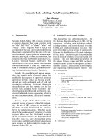
distribution flow can be simulated in an autonomous sensor node that is shown in Fig. 1.
Fig. 1. Thermoelectric energy conversion and distribution flow in an autonomous WSN.
Electric power is produced by a temperature difference between the ambient and the hot
surface of a thermoelectric module TEM heated by a waste heat coming from industrial
processes, geothermal, isotopic, burned fossil fuels or even human warmth. After that, the
generated low voltage is boosted up in a DC/DC converter or a charge pump CP. Next, in
power management unit PM the available energy is distributed between autonomous
wireless sensor node WSN and the energy storage EST.
A key concern, when designing TEGs for energy harvesters, is not the efficiency but the
maximum power transfer to the load. Therefore it is very essential to perform – prior to
TEM
CP
PM
EST
WSN
heat
Modeling and Simulation of Thermoelectric Energy Harvesting Processes
111
physical design - series of simulation experiments for different scenarios in order to
extract as much as possible electrical power. The presented model is useful in forecasting
the operation of TEGs under different conditions relating to temperature as well
electrical domains. Even with the best DC/DC converter boosting up the voltage to
supplying an electronic circuitry one has to remember that the thermoelectric energy
harvesting is a low efficiency method and there is not much power available. Therefore a
lot of effort should be invested in simulation and design stage of energy harvesters based
on Peltier modules.
In the next following paragraphs basics of thermoelectric modules based on Peltier
devices are shown, with the phenomena that rule their operation and are crucial for
comprehensive understanding of heat to electric energy conversion. After that an
analytical description of the heat flux and power generation in TEMs is presented,
followed by electrothermal modelling in electronic circuit simulator. At the end a set of
simulations scenarios for thermogenerator based on a commercially available
thermoelectric module is shown. The results of simulations experiments are very useful in
predicting maximum ratings of the TEGs during operation under different ambient
conditions and electrical loads.
2. Basics of thermoelectric generators
Thermoelectric generator TEG is a solid-state device based on a Peltier module, capable of
converting heat into electrical energy. In the opposite mode of work when it is supplied
with DC current it is able to pump heat, which in consequence leads to cooling one of its
sides whereas heating of the other The Peltier module consists of N pairs of thermocouples
connected electrically in series and thermally in parallel. They are sandwiched between two
ceramic plates which are well conducting heat but on the other hand representing high
electrical resistance (Fig. 2).
Fig. 2. Thermoelectric module.
Thermoelectric material is characterized by the figure of merit Z which is a measure of its
suitability for thermoelectric applications (1). Good materials should have high Seebeck
coefficient α, low electrical resistivity ρ and low thermal conductivity λ.
2
Z
α
ρ
λ
= (1)
Sustainable Energy Harvesting Technologies – Past, Present and Future
112
The most commonly used thermocouples in modules are made of heavily doped bismuth
telluride Bi
2
Te
3
. They are connected by thin copper strips in meander shape and covered by
two alumina Al
2
O
3
plates.
The overall operation of a TEG is governed by five phenomena, i.e.: Seebeck, Peltier,
Thomson, Joule and thermal conduction in the materials. Some of them foster thermoelectric
conversion but a few of them limit the TEG performance.
2.1 Seebeck effect
Seebeck Effect describes the induction of a voltage
V
S
in a circuit consisting of two different
conducting materials, whose connections are at different temperatures. In case of a Peltier
module the Seebeck voltage can be expressed as in (2), where T
h
-T
c
is the temperature
gradient across the junctions located at the opposite sides of the module.
(
)
Shc
VTT
α
=− (2)
2.2 Peltier effect
Peltier phenomenon describes the processes occurring at the junction of two different
conducting materials in the presence of a flowing electrical current. Depending on the
direction of current flow the junction absorbs or dissipates heat to the surroundings. The
amount of absorbed or dissipated heat is proportional to the electrical current and the
absolute temperature
T. The heat power associated with the Peltier phenomenon can be
calculated as in (3),
P
QITI
π
α
=
= (3)
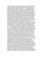
Fig. 3. Seebeck coefficient against temperature.
where
I is the electrical current flowing in the thermoelectric module, π is the Peltier
coefficient that can be expressed by means of Seebeck coefficient
α. For bismuth telluride,
Seebeck coefficient is not constant but slightly temperature dependent. In Fig. 3, function of
Modeling and Simulation of Thermoelectric Energy Harvesting Processes
113
the Seebeck coefficient against temperature, for a commercially available thermoelectric
module is shown.
Peltier effect is the basis of the thermoelectric coolers, while the Seebeck effect is used in
electrical power generators.
2.3 Thomson effect
Thomson phenomenon takes place in presence of an electrical current flowing not through a
junction of two materials as in Peltier effect but in a homogeneous electrical conductor
placed between objects at two different temperatures. Depending on the direction of current
flow, a heat is absorbed or dissipated from the conductor volume. For instance, if the
electrons are the current carriers and move towards higher temperatures, in order to
maintain thermal equilibrium they must take an energy as heat from the outside. The
reverse situation occurs in the opposite direction of the current flow. Quantitative model of
this effect is described by (4) (Lovell et al., 1981),
tT
dT
QI
dx
μ
=
−⋅⋅
(4)
where
µ
T
is the Thomson coefficient.
The influence of Thomson effect on performance of thermoelectric devices is very weak,
however it exists and cannot be neglected for very high temperature gradients.
2.4 Joule heat phenomenon
Joule heat generation is the most commonly known phenomena associated with a current
flowing in electrical circuits. Opposite to the previously described phenomena, Joule effect is
not reversible and it manifests in a heat dissipated by material with non-zero resistance in
the presence of electrical current (5).
2
j
QIR
=
⋅
(5)
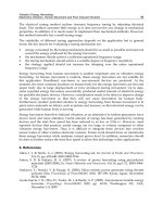
Fig. 4. Internal resistance of a thermoelectric module against temperature.
2.0
2.4
2.8
3.2
80%
R [Ω]
1.6
120
100
80
-20
40 60
0
20
T
[
o
C
]
Sustainable Energy Harvesting Technologies – Past, Present and Future
114
In Fig. 4, a temperature function of the internal resistance of a thermoelectric module is
shown.
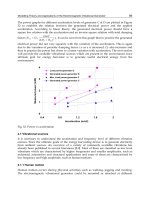
2.5 Heat conduction
Heat flow and conduction between two sides of a thermoelectric module is described in
details in the next paragraph. An important difficulty in describing this phenomenon in the
case of Peltier modules is a significant temperature difference across the active material of
Bi
2
Te
3
and more over the strong temperature dependence of the thermal conductivity K, as
shown in Fig. 5.
Fig. 5. Thermal conductivity of a thermoelectric device against temperature.
2.6 Power generation
When a thermoelectric couple or a meander of serially connected pairs is placed between
two objects at two different temperatures T
c
and T
h
- e.g. a heat sink and a heat source - it
can produce Seebeck voltage V
S
(Fig. 6). In this case only Seebeck effect and heat conduction
phenomenon occur.
If the electromotive force
V
S
is closed by a resistive load R
L
then an electrical power P is
generated (6) and the thermoelectric module is utilizing all the described phenomena.
()
2
2
2
hc
S
LL L
LI LI
TT
V
PIR R R
RR RR
α
⎛⎞
−
⎛⎞
== =
⎜⎟
⎜⎟
⎜⎟
++
⎝⎠
⎝⎠
(6)
Where,
R
I
is the internal resistance of the thermoelectric couples made of bismuth telluride.
2.7 Benefits of thermoelectric generators
Thermoelectric modules manifest some advantages when the other harvesting methods and
sources of energy coming from the environment are considered. First of all, thermoelectric
generation is some kind of solid state power conversion. Therefore the Peltier devices do not
0.4
0.5
0.6
0.7
0.8
K [W/
o
C]
81.4%
120
100
80
-20
40 60
0
20
T
[
o
C
]
Modeling and Simulation of Thermoelectric Energy Harvesting Processes
115
have any moving parts, so they are reliable, silent and they are characterized by very long
MTF (mean time to failure). Moreover they are not chemically hazardous. Next, opposite to
photovoltaic panels they can operate in conditions where there light is not sufficient or not
available at all. Finally, temperature gradients have tendency to change rather more slowly
than the amplitudes of vibrations which often are occurring as single bursts. Therefore,
thermoelectric generators can provide energy in a continuous way.
Fig. 6. Power generation by a single thermocouple exposed to a temperature gradient.
3. Analytical analysis of thermoelectric devices
During considerations on modeling of thermoelectrical energy processes generation one has
to take into account electrothermal interactions between a few phenomena that form a
feedback loop as depicted in Fig. 7.
Fig. 7. Electrothermal interactions in thermoelectric modules working as TEGs.
A temperature gradient
∆T resulting from different ambient conditions between two sides of
Peltier module causes that a Seebeck voltage V
S
appears. If the circuit is closed by a certain
p
n
Q
h
Heat sink
T
h
T
c
T
a
R
L
V
S
Q
c
I
Temperature
gradient
∆T=(T
h
-T
c
)
Seebeck
voltage
V
S
=α(T
h
-T
c
)
Peltier current I
and
Joule heat
P=I
2
R
I
Sustainable Energy Harvesting Technologies – Past, Present and Future
116
resistive load R
L
, the voltage V
S
forces a Peltier current I flow, and in consequence there
appears a Joule heat resulting from dissipated power in the internal resistance
R
I
of the
Peltier module. Joule heat introduces some temperature disturbance to the existing
temperature gradient, and thus influences on the Seebeck voltage. Then the whole cycle
starts again.
In order to derive quantitative description of the TEG operation a layered model will be
analysed which is shown in Fig. 8. The passive elements of the TEG will be described by
means of the general equation of heat conduction (7), while the active parts will be modeled
according to the constant parameters theory (Buist, 1995).
()()
(
)
,,,
,,, ,,,
Tx
y
zt
Txyzt wxyzt C
t
ϑ
∂
λ
∂
∇+ = (7)
Fig. 8. Layered model of a thermoelectric generator subjected to analysis.
Where, w is generated heat power density distribution, C
ϑ
is the specific heat capacity
coefficient.
3.1 Heat conduction in passive layers of a thermoelectric module
With a good approximation it can be assumed one-directional heat flow due to much larger
planar dimensions of the thermoelectric generator than the lateral ones. It means that the
surfaces that are parallel to the direction of heat flow can be treated as adiabatic ones (8) (De
Baetselier et al., 1995b).
S
P
Q =
heat sink
x
thermoelectric module
heat power source
Al
2
O
3
Al
2
O
3
Bi
2
Te
3
Bi
2
Te
3
Al
2
O
3
Cu
Cu
Al
2
O
3
Modeling and Simulation of Thermoelectric Energy Harvesting Processes
117
(
)
(
)
,, ,,
0, 0
Txyz Txyz
yz
∂∂
∂∂
=
= (8)
Differential equation for a heat flow in a steady state, without internal heat sources, can be
expressed by (9). In (10) and (11), boundary conditions for interfaces between heat source
and Al
2
O
3
as well as Al
2
O
3
and copper strips are presented.
2
2
0
dT
dx
= (9)
23 23
0
A
lO AlO
x
dT P
dx S
λ
=
=
⋅
(10)
23
23
23
0
()
()
Al O
Al O
Cu
Al O Cu
x
xl
dT x
dT x
dx dx
λλ
=
=
=
(11)
Finally, for the galvanic connection between copper layer and the cold side of the bismuth
telluride, the temperature is equal to
T
h
– temperature of the hot side of the active part of the
TEG (12).
()
Cu
Cu h
xl
Tx T
=
=
(12)
For the opposite side of the thermoelectric modules we can derive similar equations, except
that the Al
2
O
3
layer at the cold surface is adjacent to a heat sink (13).
23
23
23
0
()
()
Al O
Al O
hs
Al O hs
x
xl
dT x
dT x
dx dx
λλ
=
=
=
(13)
The other side of the heat sink is exposed to an ambient temperature Ta. The heat is
transferred to the surrounding environment by radiation and convection which are
described by the average heat transfer coefficient h (14) (Kos, 1994).
()
hs a
hs
xhs
dT h
TT
dx
λ
=
=− −
(14)
3.2 Heat flow and power generation in active part of a thermoelectric module
According to the thermoelectric theory based on constant parameters the active part of a
thermoelectric generator can be described by a set of three equations. Two of them are
relating to the thermal domain and represent heat powers Q
c
at the cold side (15), and Q
h
at
the hot one (16), while the last one comes from the electrical domain and represents an
electrical circuit consisting of an electromotive force V
S
causing a Peltier current I
flow (17).
Sustainable Energy Harvesting Technologies – Past, Present and Future
118
()
23
23 23
2
123
()
() ()
2
Bi Te
c Bi Te c Bi Te h c c c c
IR T
Q TTI K TTT Q Q Q
α
⋅
= ⋅⋅− − ⋅−=−−
(15)
()
23
23 23
2
123
()
() ()
2
Bi Te
hBiTe h BiTe hc h h h
IR T
Q TTI K TTT Q Q Q
α
⋅
=⋅⋅+ −⋅−=+−
(16)
() ()
23 23
SBiTe hBiTe c
VTTTT
αα
⎡
⎤
=
⋅− ⋅
⎣
⎦
(17)
Neglecting the Thomson effect, the thermoelectric device can be shown as two heat power
generators (Fig. 9) consisting of components responsible for Peltier effect Q
c1
and Q
h1
, Joule
heat Q
c2
and Q
h2
, heat conduction Q
c3
and Q
h3
. In case of the Joule heat it is assumed that one
half of it dissipates at the cold side and the other half flows to the other side of the
thermoelectric generator.
Fig. 9. Cross section of the active part of a Peltier module with two heat power generators.
4. Electrothermal model of thermoelectric generator based on Peltier
modules
Complexity of the electrothermal behaviour of thermoelectric devices - that is described by
nonlinear differential equations - can be represented and solved by means of finite element
modeling (FEM). However, such a sophisticated tool is impractical from the electronic
engineers’ point of view who need intuitively easy to understand and user friendly simulators.
An electrothermal model of a TEG based on Peltier module makes possible for engineers to
carry out investigations - not necessarily going into physical details - on free power
T
h
(t)
T
c
(t)
Q
h
=
α
Bi2Te3
·T
h
(t)·I(t)
Q
c
=
α
Bi2Te3
·T
c
(t)·I(t)
x
Cu
Cu
Al
2
O
3
Al
2
O
3
P
j
=R·I
2
(t)
Bi
2
Te
3
Modeling and Simulation of Thermoelectric Energy Harvesting Processes
119
generators converting some available ambient energy. To properly model electro-thermal
phenomena in SPICE-like simulators the well known analogy has to be used, where:
temperature T corresponds to electrical voltage V, heat flux Q to electrical current I, and
thermal resistance R
th
to electrical resistance R.
Due to the fact that the SPICE-like simulators are dedicated to simulations of only electric
phenomena, the whole synthesised equivalent circuit representing all the physical aspects of
a TEG operation has to be separated into two different circuits: one representing thermal
phenomena and the other for electrical ones (Fig. 10). These two circuits are in mutual
interaction by exchanging information about generated heat flux Q and changing
temperature T. The real electrical circuit represents an electromotive force the V
S
that causes
a Peltier current flow and in consequence Joule heat generation. The heat flux Q is converted
into thermal domain by means of an auxiliary thermal circuit and influences on the
operation of the thermal model of the TEG that is represented by a real thermal circuit. Next,
it introduces some changes in temperature distribution which in turn, by means of an
auxiliary electrical circuit, modifies the Seebeck voltage. By means of the electrothermal
analogy, only equivalent electrical elements are needed to be used for modelling of heat
conduction as well as power heat generation.
Fig. 10. Block diagram illustrating interaction between the electrical circuit and the thermal
equivalent circuit.
4.1 Synthesis of the equivalent electrothermal model of a TEG
By solving the set of equations (9)-(12) describing heat conduction in passive layers of the
TEG, the formulas for the hot and cold sides respectively are obtained in (18) and (19)
(Janke, 1992). They can be treated as Kirchhoff’s law in thermal domain.
()
23
23
23 23
_ __
Al O
Cu
heat source h h th Al O th Cu
Al O Al O Cu Cu
l
l
TTP TPRR
SS
λλ
⎛⎞
⎜⎟
=+ + =+ +
⎜⎟
⋅⋅
⎝⎠
(18)
Electrical circuit
T
Real electrical
circuit
Auxiliary
electrical circuit
Thermal equivalent circuit
Auxiliary
thermal circuit
Real thermal
circuit
Q
Sustainable Energy Harvesting Technologies – Past, Present and Future
120
(
)
23
__ _ca cthhsthAlO thCu
TTQR R R=+ + +
(19)
R
th_hs
is the thermal resistance represented by a heat sink and it takes into account heat
conduction, convection as well as radiation (20).
_
1
hs
th hs
hs hs hs
l
R
ShS
λ
=+
⋅
⋅
(20)
Appropriate model should also describe the behaviour of the TEG in transient states. For
this purpose a concept of thermal capacity C
th
is introduced. Interpretation of the thermal
capacity is obtained by comparing the temperature impulse response characteristics for a
single layer with the analytical solution of this problem. As a result, the thermal capacity for
a single layer can be expressed as in (21) (Janke, 1992).
2
4
th
th
ClS
C
R
ϑ
τ
π
⋅
⋅⋅
==
(21)
From equations (18)-(21) one can easily derive equivalent passive elements of the TEG that
form an equivalent circuit. After connection the active heat power sources and Seebeck
voltage described in (15)-(17) a complete model is obtained (Fig. 11).
Fig. 11. Complete equivalent electrothermal model of a thermoelectric generator.
The final model of the TEG was converted to a netlist and implemented into electronic
circuits simulator. To get products of some quantities that constitute
Q
c
, Q
h
and V
s
, auxiliary
voltage dependent current sources were used.
R
L
(+)
(-)
(
)
(
)
chTeBiS
TTTV −⋅=
32
α
(
)
TR
TeBi
32
Q
c
R
th_Al203
Q
h
T
a
T
c
T
h
R
th_Cu
C
th_ Cu
C
th_Al2O3
R
th_ Cu
R
th_Al203
C
th_ Al2O3
C
th_Cu
R
th_hs
C
th hs
Q
p
R
th_heat_source
C
th heat source
Heat
source
Heat
sink
Thermoelectric module
Modeling and Simulation of Thermoelectric Energy Harvesting Processes
121
Fig. 12. A part of a SPICE notation describing the cold heat power source.
In the SPICE notation, the final model of the TEG is seen as a subcircuit consisting of four
terminals, as shown in Fig. 13.
Fig. 13. Macromodel of TEG.
Nodes TC and TH represent temperatures in
o
C at the cold and hot sides respectively, while
TA refers to an ambient temperature. These three input terminals come from thermal
equivalent circuit and during simulations in SPICE they are seen as voltages. They can be
connected to the voltage sources (any function) and then the conditions would be similar to
those as the TEG was placed between two objects of infinite thermal capacity. They can also
be connected to the passive thermal circuits or the heat sources, of any time functions, that
are represented in equivalent circuits by current sources. The terminal VS comes from
electrical part of the model. It is the output node where Seebeck voltage appears. It can be
connected to any kind of a resistive load to simulate real conditions of energy harvesting
processes.
4.2 Improved electrothermal model
Assumption about constant parameters α, R, K seems to be a simplified solution in view of
the temperature range the TEG is going to work in, and because of the actual temperature
dependency of the parameters, because they show strong nonlinear temperature
dependency as it was presented in Fig. 3 – Fig. 5. In typical working conditions, common in
the industrial environment, for temperatures ranging from -20
o
C to 120
o
C, the parameters
can change their values from 13% (for
α) beyond 80% (for K)!
Gamc 0 11 POLY(1) 100 0 11.03m 28.6u -188n
Rtym_amc 11 0 1
Gqc1 100 500 POLY(3) 11 0 110 0 300 0 0 0 0 0 0 0 0 0 0 0 0 0 0 0 1
Grmc 0 22 POLY(1) 100 0 352m 1.7m
Rtym_rmc 22 0 1
Gqc2 500 100 POLY(2) 22 0 300 0 0 0 0 0 0 0 0 0 0.5
Gkmc 0 33 POLY(1) 100 0 174m 290u 7.25u
Rtym_kmc 33 0 1
Gqc3 500 100 POLY(3) 33 0 200 0 100 0 0 0 0 0 0 1 -1
Electrothermal
Macromodel
of TEG
TH
TA
TC
VS
Sustainable Energy Harvesting Technologies – Past, Present and Future
122
To increase the accuracy of the model some modifications were made. Among others, the
dependencies of the coefficients:
α
, R, K, on temperature were introduced. Their changes
with temperature were taken into consideration and implemented into the model by
approximation of polynomial second order functions. It was assumed that the temperature
argument
T appearing in equations (15)-(17) should match the average temperature T
av
between the two sides of the thermoelectric module (Seifert et al., 2001).
4.3 Experimental characterization of thermoelectric modules
Unfortunately, temperature characteristics of the coefficients of thermoelectric modules are
not disclosed to the users by manufacturers, as a general rule. Due to this fact, before they
can be taken advantage of, in constructing of an electrothermal model, first they need to be
calculated during experimental characterization processes.
Methodology for extracting thermoelectric module parameters can be found in the work
(Mitrani et al., 2005). Slightly different approach was demonstrated by (Dalola et al., 2008).
To determine temperature dependences of Seebeck coefficient
α
Bi2Te3
and electrical resistance
of thermoelectric couples
R
Bi2Te3
the TEM under test should be placed between two objects of
controlled in a wide range temperatures
T
c
and T
h
. From measured output voltage V
O
and
electrical current
I the two parameters can be derived as in (22) and (23).
23
0
O
Bi Te I
hc
V
TT
α
=
=
−
(22)
23
0OI O
Bi Te
VV
R
I
=
−
=
(23)
Experimental measurement of the thermal conductivity
K
Bi2Te3
brings about much more
problems because to its determination a heat flux
Q should be known. Therefore, some
modification in measurement setup which is shown in Fig. 14 is necessary.
Temperature of the cold side of the thermoelectric module under test is controlled in a
closed feedback loop by an auxiliary thermoelectric cooler. The other side of the module is
fixed to an auxiliary heat conducting block made of aluminum or copper, with adiabatic
surfaces. The other end of the block is fixed to an auxiliary TEM with controlled
temperature T
x
, which is higher than T
c
. Provided that the thermal conductivity coefficient
of the auxiliary conducting block is known, the heat flux is easily obtained as in (24).
(
)
hxAlhc
QQ TT
λ
== − (24)
Taking into account the equation (14), thermal conductivity for bismuth telluride active part
can be calculated as in (25).
()
23 23
23
2
0.5
Bi Te h Bi Te Al h x
Bi Te
hc
TI I R T T
K
TT
αα
+−−
=
−
(25)
The obtained temperature characteristics of the main three parameters are approximated by
polynomial second order functions, which for the examined Peltier device were shown in
Modeling and Simulation of Thermoelectric Energy Harvesting Processes
123
Fig. 3 – Fig. 5. The coefficients staying before variables in the approximated functions are
next introduced to the core netlist notation of the SPICE-like simulators.
Fig. 14. Measurement setup for characterization of thermoelectric modules.
5. Simulations of energy harvesting processes in thermoelectric generators
The crucial part in the whole design process of TEGs is the modeling and electrothermal
simulations which can provide good estimations of electrical energy that can be obtained
from heat conversion. Properly designed generator requires many simulations during
design stage against different conditions, so as to obtain as much as possible electrical
energy from a relatively low efficiency system. In some cases it can replace prototyping of
complex designs. The implemented macromodel of TEG into SPICE-like simulators makes
possible to perform different simulation scenarios. In the next following examples some
results of simulations experiments that were performed by means of the electrothermal
model of TEG and electronic circuits simulator SPICE are presented. They give quantitative
information about behaviour of the real TEG under different thermal and electrical
conditions often occurring in practice. All the presented simulations were performed for a
127 pairs commercially available thermoelectric module for which the approximated
polynomial functions look like in (26)-(28).
(
)
23
72 4 3
7 10 1 10 49.1 10
Bi Te
TTT
α
−
−−
=− ⋅ + ⋅ + ⋅ (26)
(
)
23
3
10.1 10 1.98
Bi Te
RT T
−
=⋅ + (27)
(28)
( )
4626.0102.2104
325
32
+
⋅
−
⋅
=
−
−
TTT
K
Te
B
i
Sustainable Energy Harvesting Technologies – Past, Present and Future
124
5.1 Examples of simulations
Output voltage V
S
from the TEG for R
L
=∞ is shown in the Fig. 15. The simulations were
performed for different temperature gradients by setting T
c
as parameter and T
h
as an
argument. A scheme of the equivalent circuit for the presented simulations is shown next to
the characteristics.
Fig. 15. Output voltage V
S
versus temperature of the hot side and constant T
C
.
The graphs allow estimating maximum ratings of voltages when no resistive load is present.
They can be very useful in the course of designing DC-DC boost regulators pushing up the
voltage to the level required by an electronic circuitry, for example sensor nodes.
In the Fig. 16 an output power P
L
in relation to a resistive load R
L
and different temperature
gradients ∆T is depicted. From the simulated functions one can find the points of the best
matching between R
L
and the inner resistance of the Peltier module. It is worth mentioning
that the maximum power transfer point (MPTP) is not constant but moves in the direction of
higher R
L
as the temperature gradient ∆T is increasing.
Fig. 16. Output power P
L
versus resistive load and constant temperature gradient ∆T.
Modeling and Simulation of Thermoelectric Energy Harvesting Processes
125
Fig. 17. Output power P
L
versus resistive load R
L
and the same temperature gradients ∆T,
located in low, medium and high temperatures.
Next, the Fig. 17 shows the output power P
L
in the function of R
L
for the same ∆T=20
o
, in
low, medium and high temperatures. From this picture it is evident to designers that the
maximum output power P
L
depends not only on R
L
and ∆T, but also on the temperature
range the ∆T gradient is located in.
Functions of coefficient of performance COP, defined as in (29), are shown in Fig. 18 and Fig
19. They both present conversion efficiency in relation to a resistive load R
L
and a heat
power Q
h
. It can be observed that COP does not exceed 12%.
100%
L
h
P
COP
Q
=⋅
(29)
Fig. 18. Coefficient of performance COP versus heat power of the hot side and constant R
L
.
Results presented in Fig. 20 illustrate importance of proper selection of the heat sink that is
attached to the cold side of the module on the overall performance of TEG. From the point
of view of the output voltage, it seems that the thermal resistance R
th_hs
of the heat sink
should be chosen as low as possible, so that the high heat power Q
h
would resulted in a
Sustainable Energy Harvesting Technologies – Past, Present and Future
126
large enough temperature gradient across the Peltier module. Otherwise, too high R
th_hs
might squander the whole effort that was made to improve the overall system efficiency. On
the other hand it can be proved that similarly to the idea of electrical matching, the
maximum power transfer can be provided if the thermal resistance of the heat sink is
matched with thermal resistance of the thermoelectric module.
Fig. 19. Coefficient of performance COP versus resistive load R
L
.
Fig. 20. Output voltage V
S
versus thermal resistance of a heat sink.
6. Conclusion
Thermoelectric generators fulfill a very important role in some niche applications, for
example they provide energy for satellites and space equipment. Smaller TEGs can supply
electrical energy to remote distant low power consumption objects and when there is no
electricity nearby. Thermoelectric modules applied as electrical energy generators can be
treated as potential sources of green energy, although as a matter of fact they suffer from
relatively low efficiency so far. Hopefully, with new materials technology development
TEGs will have better energy conversion coefficients of performance in the future. However,
Modeling and Simulation of Thermoelectric Energy Harvesting Processes
127
it is obvious that for energy harvesting applications Peltier devices can have a very high
potential impact.
Presented electrothermal model took into account both thermal and electrical phenomena
taking place in Peltier modules. The model is easy to adapt in any electronic circuits
simulator, especially in SPICE which has well established position as convenient and
reliable software among electronic engineers. The improved version of the model took also
the temperature dependent coefficients, describing operation of the TEGs, into
consideration, thus leading to its increased accuracy.
Obtained experimental simulations give a number of interesting insights into interactions
between TEG, surrounding environment and the electrical load. In this way, they make
possible to perform qualitative analysis of energy harvesting processes. They proved the
usefulness of the model for designers of the real harvesters made of Peltier modules, thanks
to the fact that the whole design process is then more cost effective and efficient.
Future research work will be focused on more accurate modeling of temperature functions
of the crucial parameters. In fact the average temperature T
av
that is used in the improved
model for determining actual values of the coefficients should be calculated by integration
of the nonlinear temperature profiles of coefficients along the pellets. This issue should be
taken into account especially for high temperature gradients.
7. Acknowledgement
The work was supported by the National Centre for Research and Development (NCBiR)
project grant No. R02 0073 06/2009.
8. References
Anatychuk L. I. (1995). Thermoelectrically Cooled Radiation Detectors, CRC Handbook of
Thermoelectrics, CRC Press 1995, pp. 633-640.
Beeby S., White N. (2010). Energy Harvesting for Autonomous Systems, Artech House, 2010,
ISBN-13: 978-1-59693-718-5.
Buist R. J. (1995). Calculation of Peltier device performance, CRC Handbook of Thermoelectrics,
CRC Press 1995, pp. 143-155.
Chen M., Rosendahl L. A., Condra T. J., Pedersen J. K. (2009). Numerical Modeling of
Thermoelectric Generators With Varing Material Properties in a Circuit Simulator,
IEEE Transactions on Energy Conversion, Vol. 24, No. 1, March 2009, pp. 112-124.
Dalola S., Ferrari M., Ferrari V., Guizzetti D. M., Taroni A. (2008). Characterization of
Thermoelectric Modules for Powering Autonomous Sensors, IEEE Transactions on
Instrumentation and Measurement, Vol. 58, No. 1, January 2009, pp. 99-107.
De Baetselier E., De Mey G., Kos A. (1995a). Thermal Image Generator as a Vision Prosthesis
for the Blind, MST Poland News, No. 3(7), October 1997, pp. 3-5.
De Baetselier E., Goedertier W., De Mey G. (1995b). Thermoregulation of IC’s with high
power dissipation, Proceedings of the 10th European hybrid Microelectronics Conference,
Copenhagen, Denmark, May 1995, ISHM, pp. 425-439.
Dziurdzia P., Kos A. (1999). Electrothermal Macromodel of Active Heat Sink for Cooling
Process Simulation, Proc. of the 5-th International Workshop on Thermal Investigations
of Ics and Microstructures, Roma, Italy, October 4-6, 1999, pp.76-81.
Sustainable Energy Harvesting Technologies – Past, Present and Future
128
Dziurdzia P., Kos A. (2000). High Efficiency Active Cooling System, Proceedings. of the XVIth
Annual IEEE Semiconductor Thermal Measurement and Management Symposium
SEMITHERM, San Jose, USA, 21-23 March 2000, pp. 19-26.
Freunek M., Muller M., Ungan T., Walker W., Reindl L. M. (2009). New Physical Model for
Thermoelectric Generators, Journal of Electronic Materials, Vol. 38, No. 7, 2009, pp.
1214-1220.
Janke W. (1992). Zjawiska termiczne w elementach i układach półprzewodnikowych, Układy
i systemy elektroniczne, Wydawnictwa Naukowo - Techniczne, Warszawa 1992.
Joseph A. D. (2005). Energy Harvesting Projects, Published by the IEEE CS and IEEE ComSoc,
1536-1268/05.
Kos A. (1995). Modelowanie hybrydowych układów mocy i optymalizacja ich konstrukcji ze
względu na rozkład temperatury, Rozprawy Monografie, Wydawnictwa AGH,
Kraków 1994.
Kotanagi S. et al. (1999). Watch Provided with Thermoelectric Generator Unit, Patent No.
WO/1999/019775.
Lineykin S., Ben-Yaakov S. (2005). Analysis of thermoelectric coolers by a spice-compatible
equivalent-circuit model, Power Electronics Letter IEEE, Volume 3, Issue 2, 2005, pp.
63-66.
Lovell M. C., Avery A. J., Vernon M. W. (19821). Physical properties of materials, Van
Nostrand Reinhold Company, University Press, Cambridge 1981.
Luo J., Chen Y., Tang K., Luo J. (2009). Remote monitoring information system and its
applications based on the Internet of Things, BioMedical Information Engineering,
2009. FBIE 2009. International Conference on Future , 13-14 Dec. 2009, pp.482-485.
Mateu L., Codrea C., Lucas N., Pollak M., Spies P. (2007). Human Body Energy Harvesting
Thermogenerator for Sensing Applications, Proc. of the International Conference on Sensor
Technologies and Applications SensorComm 2007, October, Valencia, Spain, pp. 366-372.
McNaughton A. G. (1995). Commercially Available Generators, CRC Handbook of
Thermoelectrics, CRC Press 1995, pp. 659-469.
Mitrani D., Tome J. A., Salazar J., Turo A., Garcia M. J., Chavez A. (2005). Methodology for
Extracting Thermoelectric Module Parameters, IEEE Transactions on Instrumentation
and Measurement, Vol. 54, No. 4, August 2005, pp. 1548-1552.
Paradiso J. A., Starner T. (2005). Energy Scavenging for Mobile and Wireless Electronics,
Pervasive Computing, IEEE, Jan March 2005, pp. 18-27.
Penn A. (1974). Small electrical power sources, Phys. Technol, 5, 114,1974.
Priya S., Inman D. J. (2009). Energy Harvesting Technologies, Springer, 2009, ISBN 978-0-387-
76463-4.
Redstall R. M., Studd R. (1995). Reliability of Peltier Coolers in Fiber-Optic Laser Packages,
CRC Handbook of Thermoelectrics, CRC Press 1995, pp. 641-645.
Salerno D. (2010). Ultralow Voltage Energy Harvester Uses Thermoeletric Generator for
Battery-free Wireless Sensors, LT
Journal, 2010, pp. 1-11.
Seifert W., Ueltzen M., Strumpel C., Heiliger W., Muller E. (2001). One-Dimensional
Modeling of a Peltier Element, Proc. of the 20
th
International Conference on
Thermoelectrics, 2001.
Uemura K. (1995). Laboratory Equipment, CRC Handbook of Thermoelectrics, CRC Press 1995,
pp. 647-655.
Wey T. (2006). On the Behavioral Modeling of a Thermoelectric Cooler and Mechanical
Assembly, IEEE North-East Workshop on Circuit and Systems, 2006, pp. 277-280.