Sustainable Energy Harvesting Technologies Past Present and Future Part 9 pdf
Bạn đang xem bản rút gọn của tài liệu. Xem và tải ngay bản đầy đủ của tài liệu tại đây (1.2 MB, 20 trang )
WSN Design for Unlimited Lifetime 19
Iwanicki, K. & van Steen, M. (2009). On hierarchical routing in wireless sensor networks,
Proceedings of the 2009 International Conference on Information Processing in Sensor
Networks, pp. 133–144.
Klopfenstein, L. C., Lattanzi, E. & Bogliolo, A. (2007). Implementing energetically sustainable
routing algorithms for autonomous wsns, International Symposium on a World of
Wireless, Mobile and Multimedia Networks (WoWMoM 2007) , pp. 1–6.
Kreutzer, W., Hopkins, J. & van Mierlo, M. (1997). Simjava a framework for modeling
queueing networks in java, Proceedings of the 29th conference on Winter simulation,
pp. 483–488.
Kulkarni, R., Forster, A. & Venayagamoorthy, G. (2011). Computational intelligence in wireless
sensor networks: A survey, Communications Surveys and Tutorials, IEEE 13(1): 68 – 96.
Lattanzi, E., Regini, E., Acquaviva, A. & Bogliolo, A. (2007). Energetic sustainability of
routing algorithms for energy-harvesting wireless sensor networks, Elsevier Computer
Communications 30(14-15): 2976–2986.
Levis, P., Culler, D., Gay, D., Madden, S., Patel, N., Polastre, J., Shenker, S., Szewczyk, R.
& Woo, A. (2008). The emergence of a networking primitive in wireless sensor
networks, Communications of the ACM 51(7): 99–106.
Li, C., Zhang, H., Hao, B. & Li, J. (2011). A survey on routing protocols for large-scale wireless
sensor networks, Sensors 11(4): 3498–3526.
Lin, L., Shroff, N. B. & Srikant, R. (2007). Asymptotically optimal energy-aware routing for
multihop wireless networks with renewable energy sources, IEEE/ACM Trans. Netw.
15: 1021–1034.
Mhatre, V. & Rosenberg, C. (2005). Energy and cost optimizations in wireless sensor networks:
Asurvey,in A. Girard, B. Sanso & F. Vazquez-Abad (eds), Performance Evaluation and
Planning Methods for the Next Generation Internet, Kluwer Academic Publishers.
Mottola, L. & Picco, G. P. (2011). Programming wireless sensor networks: Fundamental
concepts and state of the art, ACM Comput. Surv. 43: 19:1–19:51.
Nallusamy, R. & Duraiswamy, K. (2011). Solar powered wireless sensor networks for
environmental applications with energy efficient routing concepts: A review,
Information Technology Journal pp. 1–10.
Seraghiti, A., Delpriori, S., Lattanzi, E. & Bogliolo, A. (2008). Self-adapting maxflow routing
algorithm for wsns: practical issues and simulation-based assessment, Proceedings
of the 5th international conference on Soft computing as transdisciplinary science and
technology, pp. 688–693.
Shafiullah, G. M., Gyasi-Agyei, A. & Wolfs, P. J. (2008). A Survey of Energy-Efficient and
QoS-Aware Routing Protocols for Wireless Sensor Networks,SpringerNetherlands.
Sudevalayam, S. & Kulkarni, P. (2010). Energy harvesting sensor nodes: Survey and
implications, Communications Surveys and Tutorials, IEEE pp. 1–19.
Wang, A. Y. & Sodini, C. G. (2006). On the energy efficiency of wireless transceivers, Proc. of
IEEE Conference on Communications, pp. 3783–3788.
Yarvis, M. & Zorzi, M. (2008). Special issue on energy efficient design in wireless ad hoc and
sensor networks, Elsevier Ad Hoc Networks .
Yick, J., Mukherjee, B. & Ghosal, D. (2008). Wireless sensor network survey, Elsevier Computer
Networks 52: 2292–2330.
149
WSN Design for Unlimited Lifetime
20 Will-be-set-by-IN-TECH
Zeng, K., Ren, K., Lou, W. & Moran, P. J. (2006). Energy-aware geographic routing in lossy
wireless sensor networks with environmental energy supply, Proceedings of the 3rd
international conference on Quality of service in heterogeneous wired/wireless networks.
150
Sustainable Energy Harvesting Technologies – Past, Present and Future
0
Wearable Energy Harvesting System for
Powering Wireless Devices
Yen Kheng Tan and Wee Song Koh
Energy Research Institute @ NTU (ERI@N)
Singapore
1. Introduction
As the world trends towards ageing population UN (2011), there is an increasing demand and
interest in using technology to increase the quality of life for elderly people. An expanding
area of interest is heading towards the health care applications like wearable biometric
monitoring sensors. These monitoring nodes, typically powered by batteries, have various
functions like sensing & monitoring bodily functions, after which the data is wirelessly
transmitted to a remote data terminal Harry et al. (2009), Philippe et al. (2009). However such
applications mentioned are not new, where earlier literatures envisioned of a not too distant
future where e-textiles, electronics woven together with fabrics, are omni-present Marculescu
et al. (2003). With improving technology in miniaturization and wireless communication,
clothing containing sensors for sensing and monitoring bodily physiological functions Wixted
et al. (2007) is becoming more common and widespread. Such devices should be unobtrusive
wearable, flexible, lightweight and ideally self-sufficient.
In using batteries, the useful life of a wearable sensing device Cook et al. (2004) is usually
limited by the battery’s lifespan or capacity. Using a high energy capacity AA sized battery of
3000mAh, the life of battery powering a certain sensor node can last a maximum of 1.5 years
Kheng et al. (2010). But operation life of the wearable electronic is much longer, at least several
years. Therefore its normal operation will be interrupted whenever the supplying batteries die
out. Typically, the higher the capacity of the battery, bigger in size the battery will be. With
miniaturization, device components like sensors, accompanying electronics and board size
will shrink and get smaller. As such, wearable flexible batteries are more commonly used
to replace the larger batteries to keep pace with the shrinkage of these wearable electronics.
But capacity of a flexible thin-film battery with a volumetric size of 1.2 cm
3
is about 30 mAh,
lower than a 2850mAh capacity AA alkaline battery of volumetric size 11 cm
3
. As a result,
sustainability is often a key challenge for systems to be standalone with ’Deploy & Forget’
feature.
The addition of energy harvesting source is identified as a feasible way to increase the
device’s operation duration. Several potential ambient energy sources are discussed, with
the photovoltaic (PV) harvesting method providing the highest power density per volume of
total system Raghunathan et al. (2005). For indoor application using PV harvesting, major
challenges include: poor lighting intensity as compared to outdoor lighting intensity; limited
sized PV panel to be used if the device is to be placed in a confined area of the human body.
Such power produced by the PV panel is very small, usually in the range of hundreds of
6
2 Sustainable Energy Harvesting Technologies: Past, Present and Future
μW. Indoor light intensity in office environment is in the range of < 10 W/m
2
, compare
with 100-1000 W/m
2
for outdoor conditions Hande et al. (2007). For photovoltaic panel,
amorphous type is the best suited for indoor applications but suffers from low efficiency, in the
range of 3% - 7% Randall et al. (2002). On the other hand, PV cells provide a fairly stable DC
voltage through much of their operating space Roundy et al. (2004). Various works utilizing
solar harvesting/scavenging techniques demonstrated the suitable of indoor PV in supplying
alternate energy to small, low-power consuming devices, complemented with batteries within
the system Hande et al. (2007), Nasiri et al. (2009).
In this chapter, a flexible and self-sustainable energy solution incorporating energy harvesting
for wearable electronics is presented. Introducing of energy harvesting technique levitate
the operation of system towards self-sustainability. However for the system to be wearable,
certain amount of device flexibility or bending is needed. Generally the device should not
be rigid, not inhibit motion in any way and ideally follow as closely to the contour of the
wearer’s body. As such, in this chapter, rigid batteries like the AA size battery, PV panel,
PCB and supercapacitor are replaced with the flexible, bendable version. Capacity of a typical
flexible battery is in the range of a few tens of mAh Hahn et al. (1999), which severely restrict
the node’s operation duration if the flexible battery is the only input source. As such, an
additional input source is hybrid with the primary battery (which in this case, PV panel is
chosen as the additional input source to complement the primary battery for powering the
wireless body sensors). Flexible super capacitors with capacitance of
≈ 11 F/g has been
realized with good capacitance stability for long term usage applications Gan et al. (2009). The
rest of the chapter is organized as follows: Section II introduces the wearable energy storage
for wireless body sensor network and section III illustrates in more details about the key
part of the proposed system: flexible energy harvesting system comprising of modules like
maximum power point tracking (MPPT), current limiter, voltage regulation within the power
management circuitry and the load requirements. After which, in section IV, the hybrid of
wearable energy storage and FEH is discussed. Experimental results of the proposed system
performance are illustrated in section V and conclude the chapter with section VI.
2. Wearable energy storage for wireless body sensor network
It is anticipated that people will soon be able to carry a personal body sensor network (WBSN)
system with them that will provide users with information and various reporting capabilities
for medical, lifestyle, assisted living, sports or entertainment purposes. In the literature, some
older medical monitoring systems (such as Holter monitors) record the hosts’ data for off-line
processing and analysis. Newer wearable wireless systems provide almost instantaneous
information that help in earlier detection of abnormal conditions. There are also many such
commercial products out there to allow wearers to monitor their vital signs, for examples,
Omron health care products like blood pressure meter, thermometer and portable ECG and
Philips vital sense product and sports monitoring devices as seen in Figures.1 and 2. For these
commercially available health care products as seen in Figure.1, although they are meant to
be made for small size and portable, in actual fact, they are too big and bulky to be integrated
as part of our bodies for monitoring. Part of the reason why these products are so huge is
because of the batteries. Moreover, these products operate heavily on their onboard batteries
and if they are to conduct continuous body monitoring, their operational lifetimes are very
short, a month or even less than that.
152
Sustainable Energy Harvesting Technologies – Past, Present and Future
Wearable Energy Harvesting System for Powering Wireless Devices 3
Fig. 1. Omron healthcare products (a) portable ECG, (b) thermometer and (c) blood pressure
meter and Philips product (d) vital sense device
Fig. 2. Body worn devices for measuring activity and energy expenditure
Having said that, these body worn devices are still receiving huge attentions and commercial
demands simply because of their outstanding features, but they really need to be highly
portable and easily embeddable into our bodies for monitoring. In addition to that, the catch
with these body worn devices is the sky high prices to own an outstanding system like this,
i.e. a few hundreds or even to a thousand dollars. If there are a few more places on the human
body for close measuring and monitoring of dedicated activities like sleeping, sporting, etc., it
will cost a huge sum to implement the body monitoring system. There is no doubt about the
potential of such body worn monitoring system and the market is huge demanding for such
distributed sensing of human well beings through their vital signs. However, the present
state of arts and commercial products are limited and there are more to what they have that
could be included. As compared to the conventional large and bulky body monitoring system
mentioned earlier, the availability of microelectronics devices and micro electromechanical
systems (MEMS) like pulse oximeters, accelerometers, energy harvesting devices, etc. Wixted
et al. (2007), Cook et al. (2004) integrated with wireless technology provides an alternative,
non-invasive, distributed and self-powered method of automatic monitoring activity. In
addition, many of such miniaturized electronic devices are integrated together into each
individual person and also into their activities to enable better human-computer interaction
to achieve all-rounded monitoring of human health lifestyle and more accurate performance
assessment of the athletes as illustrated in Figure.3.
The functionality of the proposed body monitoring system in Figure.3 on each individual
human being is illustrated as follows: the sensed physiological information of the human is
stored and accumulated in the memory of the sub-GHz ultra-wide-band (UWB) transmitter
and it is periodically communicated to the UWB receiver of the base station without mutual
interference. One of the approaches is by coding the sequence or using different time slots,
the receiver can identify the transmitter from which sensor and setup the link automatically.
The received data from various smart sensors deployed around the body are then used for
performance assessment of subject under test. Wireless communication does away the wires,
hence save the wearer of this proposed body monitoring system from the phobia of wires.
153
Wearable Energy Harvesting System for Powering Wireless Devices
4 Sustainable Energy Harvesting Technologies: Past, Present and Future
Fig. 3. Human health lifestyle monitoring
Even though wires are removed, battery becomes the concern as the operational lifetime of
the energy storage is limited. The effective duration of a battery driven body monitoring
system is short in terms of days of weeks, after which the monitoring purpose is gone.
The energy problem escalates further when there is a need for the energy storage to be flexible
and wearable, able to conform to human body. According to the authors of Harry et al. (2009)
and Philippe et al. (2009), both suggested the use of thin-film battery technology to shrink the
overall package size, where lithium polymer battery sizes of 85 mm x 55 mm x 0.5 mm and
59 mm x 35 mm x 0.5 mm (PGEB0053559) to achieve the wearable energy storages. Typical
flexible (thin film solid state) batteries are constructed by depositing the components of the
battery as thin films (usually in tens of μm) on a substrate, which includes a solid substrate of
electrolyte cathode (positive electrode) and anode (negative electrode). Advantages include
small physical size, able to be used in a very broad range of temperatures, and supposedly
more eco-friendly than conventional batteries Mcdonald (2011). However, as with all batteries
applied on WBSN, they will be drained off after a certain period of time. In Harry et al.
(2009) and Philippe et al. (2009), rechargeable lithium polymer battery capacity is of 50 to 200
mAh (12 hours to 50 hours of operation) and 65 mAh at 3.7 V respectively. Clearly, wearable
energy storage alone is not able to sustain the operation of the WBSN. There is a need to seek
for a supplement flexible energy harvesting system to prolong the operational lifetime of the
WBSN.
3. Flexbile energy harvesting system
To minimize the problem associated with batteries, using of photovoltaic as an addition
energy source is proposed as a solution to complement battery (Zn-MnO
2
flexible battery
154
Sustainable Energy Harvesting Technologies – Past, Present and Future
Wearable Energy Harvesting System for Powering Wireless Devices 5
Barbic et al. (1999), rated voltage at about 1.5 V and capacity of ≈ 30 mAh) in prototype and
to prolong the operational life of the wearable device.
3.1 Characteristics of PV panel
Photovoltaic cell converts light to electricity through a physical process called the photovoltaic
effect. Light (in the form of photons) that is absorbed into the PV cell will transfer its energy
to the semiconductor device, knocking electrons loose and allowing them to flow freely.
These generated electrons are transferred between different bands (example, from the valence
to conduction bands) within the material, resulting in the buildup of voltage between two
electrodes. Electrically, a solar cell is equivalent to a current generator in parallel with an
asymmetric, non-linear resistive element (example: a diode). When illuminated, the ideal
cell will produce a photocurrent proportional to the light intensity. That photocurrent is
divided between the variable resistance of the diode and the load, in a ratio which depends
on the resistance of the load and the level of illumination. For higher resistances, more of
the photocurrent flows through the diode, resulting in a higher potential difference between
the cell terminals but a smaller current though the load. The diode thus provides the
photovoltage. Without the diode, there is nothing to drive the photocurrent through the load
Nelson (2011).
Fig. 4. Equivalent electrical circuit for a photovoltaic cell with parasite resistances
Figure.4 shows the basic equivalent circuit of a PV cell, where I
L
- light-generated current,
I
D
- reverse saturation (dark) current of the PN diode, R
s
- series resistance, R
sh
- shunt
resistance. Dark current can be viewed as caused by the potential built up over the load
and flows in the opposite direction. When the shunt resistance, R
sh
is assumed to be infinite,
the current-voltage (I-V) characteristic of the photovoltaic (PV) module can be described with
a single diode as the four-parameter model given by,
I
pv
= I
L
− I
D
ex p
V
pv
+ I
pv
R
s
N
s
n
I
V
t
− 1
(1)
where V
t
- the junction terminal voltage, N
s
is the number of cells in series and n
I
is the
diode ideality factor Celik (2007). For this prototype, off-the-shelf Sundance Solar MPT3.6-75
Sundance (2011) flexible PV panels, made up of amorphous silicon on a polymer substrate, is
used. Dimensions are about 75 mm x 72 mm x 0.5 mm. PV characterization graphs are shown
in Figures.5 and 6. At
≈ 400Lux, it is able to provide a peak power of about 0.14 mW.
Any unused energy will be stored into a flexible supercapacitor, which is ideal for energy
storage that undergoes frequent charge and discharge cycles at high current and short
155
Wearable Energy Harvesting System for Powering Wireless Devices
6 Sustainable Energy Harvesting Technologies: Past, Present and Future
Fig. 5. IV Curves of PV panel at various Lux values
Fig. 6. PV Curves of PV panel at various Lux values
Fig. 7. A flexible supercapacitor laminated using polymer-coated aluminum foil
duration. Basically the plates of a supercapacitor are filled with two layers of the identical
substance for separating the charge, instead of having dielectric, resulting in a much larger
surface area and high capacitance. Experiments using various types of electrodes and
electrolyte had been extensively carried out, like experimenting VNF electrodes in aqueous
156
Sustainable Energy Harvesting Technologies – Past, Present and Future
Wearable Energy Harvesting System for Powering Wireless Devices 7
electrolyte of different pH and also in an organic electrolyte Grace et al. (2010). Dimension of
such flexible capacitors as shown in Figure.7 can be packaged to about the same size as the
flexible battery.
3.2 Fractional open-circuit voltage MPPT technique
Maximum Power Point Tracking (MPPT) is a frequently used technique to vary the electrical
operating point of the PV module so that the module is able to deliver its maximum available
power. Various MPPT techniques are grouped into ’Direct’ or ’Indirect’ methods Salas et al.
(2005). For indirect methods ("quasi seeks"), the Maximum Power Point (MPP) is estimated
from the measures of the PV generator’s voltage and current PV, the irradiance, or using
empiric data, by mathematical expressions of numerical approximations. They do not obtain
the maximum power for any irradiance or temperature and none of them are able to obtain
the MPP exactly. But in many cases, such methods can be simple and inexpensive. The direct
methods ("true seeking methods") obtain the actual maximum power from the measures of
the PV generator’s voltage and current PV. Although Fractional Open Circuit Voltage based
MPPT method is classified as a quasi seeks method, it is also considered to be one of the
simplest and cost effective method Masoum et al. (1999). It is based on the fact that the PV
array voltage corresponding to the maximum power exhibits a linear dependence with respect
to the array open circuit voltage for different irradiation and temperature levels. Maximum
power point voltage, V
MPP
= K
oc
∗ V
oc
, where V
oc
is the open circuit voltage of the PV and
K
oc
is the voltage factor Ahmad (2010). To operate the PV panel at the MPP, the actual PV
array voltage V
pv
is compared with the reference voltage V
re f
which corresponds to the V
mpp
.
The error signal is then processed to make V
pv
= V
re f
. Normally, the panel is disconnected
from the load momentarily to sample its open circuit voltage. The fraction of the open circuit
voltage corresponding to the V
mpp
is measured and is kept in a hold circuit to function as V
re f
for the control loop.
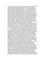
Fig. 8. Graph of Power vs Koc Constants
In Figure 8, the peak power of the PV panel is found between K
oc
constant values of 0.55 to
0.65. The K
oc
part of the control circuit will reference a K
oc
constant of 0.65 to V
oc
as V
re f
. The
control circuit will be built using discrete components and op-amps.
157
Wearable Energy Harvesting System for Powering Wireless Devices
8 Sustainable Energy Harvesting Technologies: Past, Present and Future
3.3 Ultra-low-power management circuit
The MPPT control circuitry block diagram is shown in Figure.9. It is designed to boost V
pv
to
the load when it has fallen below the V
re f
reference value. First the PV panel will break open
from rest of circuit by means of a switch. This open circuit voltage will be captured by the
K
oc
circuit, multiplied by the K
oc
constant to become V
re f
. After a certain time interval, the
PV panel will connect back with the rest of the circuit. If V
pv
< V
re f
, the error signal will be
amplified and compared with a sawtooth waveform, with the resultant signal controlling the
gate of the DC-DC converter.
Fig. 9. Block diagram of the Fractional Open Circuit Voltage MPPT control circuit
Using discrete components to build this control circuit, MOSFET are used as switches where
timing switching will be controlled by pre-programmed pulses from MSP430 MCU onboard
the end device. Koc constant of 0.65 is obtained using voltage dividing in the Koc circuit.
Op-amps, capacitors, resistors and Schottky diodes are used in various part of the circuit for
comparisons and simple sample & hold operations.
3.4 Wireless body sensor nodes/network
The wireless body sensor node is developed from the target board from Texas Instruments
eZ430-RF2500 Development Tool Texas Instruments (2011), which measures the body
temperature of the wearer and communicates wirelessly to an access point connected to a
PC. It operates between 1.8 V to 3.6 V, and measured 35 mm x 20 mm x 3.5 mm, which can
be easily placed into cloths pocket or between layers of sewn clothing. The communication
profile is captured in Figure.10.
Referring to Figure.10, during the sleep/standby mode, the target board consumes around
1.2 μA of quiescent current. During initialize stage, instantaneous current can rise up to
about 20 mA and 2 mA for burst mode transmission, which is taken care of by the flexible
supercapacitor. To reduce current consumption by the load, the target board had been
configured to transmit data at a
≈ 5 seconds transmission period. In its original mode, its
average current consumption over 1 second transmission period is 36.80 μA Texas Instruments
(2011).
I
ave
=[I
sleep
+ I
Tx,Total
]/T
Tx
(2)
158
Sustainable Energy Harvesting Technologies – Past, Present and Future
Wearable Energy Harvesting System for Powering Wireless Devices 9
Fig. 10. Zoomed-In pulse current consumption by the TI Target Board with modified
configuration of
≈ 5 second transmission period. Graph captured across a 10Ω current
sensing resistor in series with load
where
I
sleep
=[I
idle
(MSP430)+I
idle
(CC2500)] ∗ [T
Tx
(sec) − T
app
(sec)] (3)
= 1.3[μ A] ∗ (1[s] − 2.838[ms])
=
1.296A ∗ s
Therefore average current consumption over 1 second transmission period: I
ave
(1 sec Tx
period) = (1.296 [μA*s] + 35.508 [μA*s]) / 1 [s] = 36.80 μA. If transmission period is extended
to
∼5 second, the sleep current: I
sleep
(over 5 sec Tx period) = 1.3 [¸tA] * (5 [s] - 2.838 [ms]) =
6.496 μA*s and the average current consumption over 1 second: I
ave
(over 1 sec for a 5sec Tx
period) = (6.496 [μA*s] + 35.508 [μA*s])/5[s]=8.4μA
Therefore the less frequently the target board transmits, the less average current is consumed.
If using battery of 1000 mAh capacity for average current of 36.80 μA consumption, calculated
life expectancy = 1000 [mA*hrs] / 0.0368 [mA]
≈ 3.10 years. If using battery of 30 mAh
capacity for average current of 36.80 μA consumption, calculated life expectancy = 30
[mA*hrs] / 0.03680 [mA]
≈ 33.97 days. If using battery of 30mAh capacity for average current
of 8.4 μA consumption, calculated life expectancy = 30 [mA*hrs] / 0.0084 [mA]
≈ 148.8 days.
Such calculations constitute an perfect scenario, where there is no leakages, 100 % efficiency,
no power loss, no surges, and can only be used as a rough guide in the calculation of the life
expectancy of battery of certain capacity, and the actual current consumption of the node. In
the worst case scenario, the end device will keep initializing when scanning to linkup with
the access point, which will continuously draw about 18 mA of current.
159
Wearable Energy Harvesting System for Powering Wireless Devices
10 Sustainable Energy Harvesting Technologies: Past, Present and Future
4. Hybrid flexible energy harvesting and energy storage
The proposed hybrid flexible energy system prototype as seen in Figure.11 incorporate three
different types of energy sources, mainly the primary battery (flexible batteries), the secondary
battery (flexible supercapacitor, which acts as energy storage) as well as renewal energy
harvesting source like the flexible PV panel (Additional input energy to complement primary
batteries) to harvest ambient light energy.
Fig. 11. Block diagram of the proposed hybrid energy harvesting and storage system
The RF transceiver load typically has 2 modes of operation: sleep and transmission. In
sleep mode, it consumes around 1.2 μA of quiescent current, and in transmission mode, it
consumes around 2 mA of current. The default transceiver setting is set at 1 transmission
for every 1 second period. During sleep mode, the transceiver consumes very little energy,
where excess unused energy from the primary battery and PV panel will be stored in the
flexible supercapacitor. During transmission mode, the transceiver will draw energy mainly
from the supercapacitor, which is able to manage the sudden current surge. Subsequently, the
transceiver goes into sleep mode and the supercapacitor starts to recharge from the primary
battery and PV panel. To conserve energy, period between transmissions is increasing, which
decrease energy usage and increase the charging time for supercapacitor.
The overall system design of the proposed hybrid flexible energy harvesting and storage
solution is illustrated in Figure.11. The power management circuitry of the system depicted
in Figure.11 consists of: MPPT control, flexible battery current limiter and a load voltage
regulator, to be fabricated onto a flexible PCB substrate. MPPT control provides a simple
mean of impedance matching between PV panels to load. The current limiter protects the
primary battery from sudden surges. Voltage regulator maintains a steady voltage level as
required by the transceiver load. Referring to Figure.12, the MPPT control circuit is designed
to boost V
pv
to the load when it has fallen below the V
re f
value. To capture the open circuit
voltage of the PV panel, NMOS 1 will be opened to isolate the PV panel from rest of the circuit,
160
Sustainable Energy Harvesting Technologies – Past, Present and Future
Wearable Energy Harvesting System for Powering Wireless Devices 11
Fig. 12. MPPT Control Circuit using Fractional Open Circuit Voltage Approach
while NMOS 2 will be closed. The open circuit voltage will be acquired by the K
oc
circuit,
which is a voltage dividing circuit, and multiplied by the predetermined K
oc
constant of 0.65
to become V
re f
. Subsequently this V
re f
value is stored by an op amp sample and hold circuit.
Pre-programmed timers signal from MSP430 MCU onboard the TI end device will provide
the switching timing for NMOS 1 and NMOS 2. After a set timing, NMOS 2 will be opened
whereas NMOS 1 will be closed. The voltage from the PV panel, V
pv
, will be compared with
the V
re f
at the second op amp, which is a differential amplifier. When V
pv
is lower than V
re f
,
a voltage output will be sent to the ’+’ input of the LMC7215 comparator, which will compare
with the sawtooth waveform from LTC6906. This will provide switching for NMOS 3 of the
boost converter.
5. Experimental results
5.1 Performance of flexible energy harvesting system with MPPT scheme
In switching the gate of NMOS 3, there must be output from LMC7215, meaning the sample
& hold voltage (V
re f
) must be more than voltage of PV panel (V
pv
). For example, shading
over the PV panel occurs, causing V
re f
to be more than V
pv
, and switching at NMOS 3 gate
to commence. Typically the greater the difference between V
re f
and V
pv
, the larger the duty
cycle of the switching signal will be.
At
≈ 320 lux, the PV panel shows an open circuit voltage of about 1.36 V and V
pv
voltage
of about 0.3 V (Figure.13). At this lux level, the maximum power that the PV panel is able
to produce is about 76 μW, which correspond to around 0.8 V and 0.1 mA on the PV and IV
graphs. This maximum power point voltage is captured by the sample and hold circuit. When
connected to rest of the circuit, the V
pv
voltage drops to about 0.3 V, which corresponds to ≈
40 μW. There is a further voltage drop of ≈ 0.11 V drop across the Schottky diode. Therefore
the input voltage to the boost converter is around 200 mV.
The configuration of the differential op amp will influence the duty cycle to the gate of NMOS
3, which will in turn determine the output voltage of the boost converter. In an earlier
configuration, the op amp has been configured to give an output voltage where V
out
= 1/3
161
Wearable Energy Harvesting System for Powering Wireless Devices
12 Sustainable Energy Harvesting Technologies: Past, Present and Future
Fig. 13. Voltage across PV panel
Fig. 14. Voltage waveform at input of boost converter
[V(+) - V(-)]. V(+) is about 0.8 V, while V(-) is about 0.3 V. V
out
of the differential op amp
is about 0.167 V. When compared with the sawtooth waveform, duty cycle of around 30% is
produced to NMOS 3. Using boost converter formulae, V
out
= V
in
/(1 − D), output voltage of
converter is about 300 mV (200 mV / 0.7) when its input voltage is around 200 mV, as shown
in Figures.14-16.
5.2 Power conversion efficiency of FEH system
At 320 lux, the PV panel produces P
pv
= V
pv
∗ I
pv
= 300mV ∗ 0.11mA = 0.033mW when
connected to rest of circuitry. At input of boost converter, P
in
= V*I = 190 mV*0.1 mA = 19 μW.
Difference in power between P
pv
and Power at Boost converter input is due to the voltage
drop across the Schottky diode after NMOS 1. At output, P
out
= V
load
∗ I
o
= 300 mV*36 μA=
10.8 μW. Efficiency of the boost converter, η = 10.8 μW/19 μW
≈ 60%.
At 320 lux, G = 320/120
≈ 2.67 W/m
2
.
162
Sustainable Energy Harvesting Technologies – Past, Present and Future
Wearable Energy Harvesting System for Powering Wireless Devices 13
Fig. 15. Waveform at output load
Fig. 16. No switching at Gate of NMOS3 when V
re f
is less than V
pv
Table 1. Technical Characteristic of PV Panel used
Efficiency of flexible PV panel:
η
pv
=
P
pv
G ∗ A
∗ 100% (4)
=[(0.886V ∗ 86.3μA)/(2.67W/m
2
∗ 42.48cm
2
)] ∗ 100%
= 0.73%
163
Wearable Energy Harvesting System for Powering Wireless Devices
14 Sustainable Energy Harvesting Technologies: Past, Present and Future
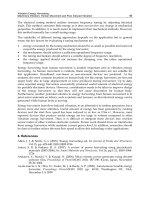
At 400 lux, the maximum power that the PV panel is able to produce is about 130 μW, which
correspond to around 1 V and 0.13 mA on the PV and IV graphs. At output of boost converter,
current is about 40 μA. Over a 5 second period, total current accumulated is 200 μA.sec, which
is able to fulfill the 0.2 mA needed by the end device for transmission in a 5 second period.
5.2.1 Power consumption study of discrete components within the fractional open circuit
voltage approach control circuit
When using a 555-timer and op-amp inverter (MAX9077) to control the opening and closing
for NMOS 1 and 2, the power consumption is shown in the next table.
Table 2. MPPT control circuit power consumption at 2.5V
From Table.2, both components (555-timer and MAX9077) take up
≈ 40 % of the total MPPT
control circuit power consumption. We can decrease the total discrete components power
consumption within the MPPT control circuit by using the RF transceiver’s MCU to provide
the timing pulse function to control NMOS 1 and 2.
5.2.2 Current limiter
A current limiter, LM334 National Semiconductor (2011) is added to protect the flexible
battery from any massive drain due to possible surge in load. At 0.14mA limit, the flexible is
able to take care of the quiescent current of the target board. If constant drawing of 0.14 mA
from a fully charged 30 mAh flexible primary battery, calculated life expectancy of flexible
battery will be: Duration = 30 [mA*hrs] / 0.14 [mA]
≈ 8.93 days
5.2.3 Voltage regulation
The voltage regulator, LTC3525-3.3 Linear Tech. (2011) is a compact, step-up DC-DC
converters used to regulate the output voltage to the target board. The regulator has a V
in
range of 0.5 V to 4.5 V, fixed output voltage of 3.3V and capable of delivering 60 mA at 3.3 V
froma1Vinput. Quiescent current is an ultra-low 7 μA, maximizing battery life in portable
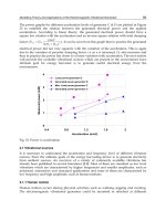
applications. Its efficiency verse load current drawn is shown in Figure 17.
5.3 Application of hybrid FEH and storage for wearable wireless body sensor network
In the placement of the prototype, the flexible batteries and supercapacitor are flexible enough
to bend along the contours of the human body, like on the forearm and shoulder.
Unlike flexible supercapacitor which has higher capacitance when twisted than any
non-twisted supercapacitor Zyga (2011), flexible PV panel will see a further decrease in
efficiency if bended as solar irradiance will decrease with less PV panel surface exposed
directly to the light source (see Figure.20).
164
Sustainable Energy Harvesting Technologies – Past, Present and Future
Wearable Energy Harvesting System for Powering Wireless Devices 15
Fig. 17. Efficiency verse load current graph of boost converter
Fig. 18. Prototype placed and wrapped around the forearm
Fig. 19. Prototype placed at shoulder
165
Wearable Energy Harvesting System for Powering Wireless Devices
16 Sustainable Energy Harvesting Technologies: Past, Present and Future
Fig. 20. Flexible PV panel placed on an arc with circular angle of 160ž
Fig. 21. PV Curves of PV panel at various Lux values when subjected to bending
From Figure.21, power produced dropped to about 1/3 of that from a flat panel. However as
a starting platform, functional experiment is conducted with a flat prototype in a controlled
environment.
Fig. 22. Constant super capacitor voltage of around 1.7 V under a constant light source of 400
lux
Referring to Figure.22, it can be seen that the functionality experiment of prototype, under a
constant light source of
≈ 400 lux, the system is self sustainable, powering the target board
166
Sustainable Energy Harvesting Technologies – Past, Present and Future
Wearable Energy Harvesting System for Powering Wireless Devices 17
and maintaining a super capacitor voltage of around 1.7 V. The experimental result verifies
that the proposed hybrid flexible energy harvesting and storage system is able to sustain the
operation of a wireless body sensor node connected in a network form.
6. Conclusions
Utilization of the PV harvesting prototypes together with its individual parts has been
introduced. Under constant light intensity of 400 lux in a controlled environment, the
prototype is able to operate in a self-sustaining mode, where the super capacitor voltage
maintains at around 1.7 V. With its flexible attribute, it can be expanded to wearable,
biomedical, constraint space applications and subsequent flexible design can be modified to
incorporate other harvesting techniques.
7. References
United Nations, Department of Economic and Social Affairs, Population Division,
"World Population Ageing: 1950-2050", > /population
/publications/worldageing19502050/< assessed on 02-09-2011.
Harry K. Charles, Jr. and Russell P. Cain, "Ultra-thin, and Flexible Physiological Monitoring
System", IEEE Sensors Applications Symposium, 2009
Philippe Jourand, Hans De Clercq, Rogier Corthout, Robert Puers, "Textile Integrated
Breathing and ECG Monitoring System", Proceedings of the Eurosensors XXIII
conference, Procedia Chemistry 1, pp.722-725, 2009.
D. Marculescu, R. Marculescu, S. Park and S. Jayaraman, "Ready to Ware", IEEE Spectrum,
pp.28-32, 2003.
A.J. Wixted, D.V. Thiel, A.G. Hahn, C.J. Gore, D.B. Pyne and D.A. James, "Measurement of
Energy Expenditure in Elite Athletes Using MEMS-Based Triaxial Accelerometers",
IEEE Sensors Journal, vol.7, no.4, pp.481-488, 2007.
D.J. Cook and S. K. Das, "Wireless Sensor Networks - Smart Environments: Technologies,
Protocols and Applications", John Wiley, New York, 2004.
Yen Kheng Tan, Sanjib Kumar Panda, "Review of Energy Harvesting Technologies for
Sustainable Wireless Sensor Network", Sustainable Wireless Sensor Networks,
INTECH Publisher, Chap 2, pp.15-43, 2010.
V. Raghunathan, A. Kansal, J. Hsu, J. Friedman and M. Srivastava, "Design Considerations
for Solar Energy Harvesting Wireless Embedded Systems", Fourth International
Symposium on Information Processing in Sensor Networks Proceedings, pp.457-462, 2005.
A. Hande, T. Polk, W. Walker, and D. Bhatia, "Indoor Solar Energy Harvesting for Sensor
Network Router Nodes", Microprocess. Microsyst., vol.31, no.6, pp.420-432, 2007.
J.F. Randall, J. Jacot, "The Performance and Modelling of 8 Photovoltaic Materials under
Variable Light Intensity and Spectra", World Renewable Energy Conference VII
Proceedings, Cologne, Germany, 2002.
S. Roundy, P.K. Wright, J.M. Rabaey, "Energy Scavenging for Wireless Sensor Networks: with
Special Focus on Vibrations". Kluwer Academic Publishers, 2004.
Adel Nasiri, Salaheddin A. Zabalawi, Goran Mandic, "Indoor Power Harvesting Using
Photovoltaic Cells for Low-Power Applications", IEEE Transactions on Industrial
Electronics, vol.56, no.11, 2009.
167
Wearable Energy Harvesting System for Powering Wireless Devices
18 Sustainable Energy Harvesting Technologies: Past, Present and Future
Robert Hahn, Herbert Reichl, "Batteries and Power Supplies for Wearable and Ubiquitous
Computing", Third International Symposium on Wearable Computers, Digest of Papers,
1999.
Hiong Yap Gan, Cheng Hwee Chua, Soon Mei Chan and Boon Keng Lok, "Performance
Characterization of Flexible Printed Supercapacitors", 11th Electronics Packaging
Technology Conference, 2009.
Jason Mcdonald, "Thin film battery technology and advanced batteries", >http://
www.eg3.com/blog/20090420.htm< assessed on 02-09-2011.
P.A. Barbic, L. Binder, S. Voss, F. Hofer and W. Grogger, "Thin-Film Zinc/Manganese Dioxide
Electrodes based on Microporous Polymer Foils", Journal of Power Sources, vol.79,
issue.2, pp.271-276, 1999.
Jenny Nelson, "The Physics of Solar Cells", Imperial College Press, >http://
www.worldscibooks.com/ physics/p276.htm< assessed on 02-09-2011.
Ali Naci Celik, Nasir Acikgoz, "Modelling and Experimental Verification of the operating
current of mono-crystalline photovoltaic modules using four- and five-parameter
models", Applied Energy, vol.84, issue.1, pp.1-15, 2007.
Sundance Solar, "Small Solar Panels for science fair projects, experiments and prototypes",
> assessed on 02-09-2011.
Grace Wee, Oscar Larsson, Madhavi Srinivasan, Magnus Berggren, Xavier Crispin,
Subodh Mhaisalkar, "Effect of the Ionic Conductivity on the Performance of
Polyelectrolyte-Based Supercapacitors", Advanced Functional Materials, pp.4344-4350,
2010.
V. Salas, E. Olit’as, A. Barrado, A. Lat’zaro, "Review of the Maximum Power Point Tracking
Algorithms for Stand-alone Photovoltaic Systems", Solar Energy Materials & Solar Cells
90 (2006), pp.1555-1578, 2005.
M.A.S. Masoum, H. Dehbonei, "Design Construction and Testing of a Voltage-based
Maximum Power Point Tracker for Small Satellite Power Supply", Proceedings of 13th
annual AIAA/USU Conference on Small Satellite, 1999.
Jawad Ahmad, "A Fractional Open Circuit Voltage Based Maximum Power Point Tracker
for Photovoltaic Arrays", 2nd International Conference on Software Technology and
Engineering (ICSTE), 2010.
Texas Instruments, eZ430-RF2500 Development Tool, Datasheet.
Texas Instruments, eZ430-RF2500 Development Tool, Application Notes.
National Semiconductor, LM334, Datasheet.
Linear Technology, LTC3525-3.3, Datasheet.
Lisa Zyga, "Paper-thin supercapacitor has higher capacitance when twisted than any
non-twisted supercapacitor", > />assessed on 02-09-2011.
Q. Zhang, P. Feng, Z.Q. Geng, X.Z. Yan, N.J. Wu, "A 2.4-GHz energy-efficient transmitter for
wireless medical applications", IEEE Transactions on Biomedical Circuits and Systems,
vol.5, no.1, pp.39-47, 2011.
O. Omeni, Alan C.W. Wong, Alison J. Burdett, C. Toumazou, "Energy efficient medium
access protocol for wireless medical body area sensor networks", IEEE Transactions
on Biomedical Circuits and Systems, vol.2, no.4, pp.251-259, 2008.
168
Sustainable Energy Harvesting Technologies – Past, Present and Future