Báo cáo hóa học: "Development and pilot testing of HEXORR: Hand EXOskeleton Rehabilitation Robot" potx
Bạn đang xem bản rút gọn của tài liệu. Xem và tải ngay bản đầy đủ của tài liệu tại đây (1.02 MB, 16 trang )
RESEA R C H Open Access
Development and pilot testing of HEXORR: Hand
EXOskeleton Rehabilitation Robot
Christopher N Schabowsky
1,2,3
, Sasha B Godfrey
1,3
, Rahsaan J Holley
4
, Peter S Lum
1,2,3*
Abstract
Background: Following acute therapeutic interventions, the majority of stroke survivors are left with a poorly
functioning hemiparetic hand. Rehabilitation robotics has shown promise in providing patients with intensive
therapy leading to functional gains. Because of the hand’s crucial role in performing activities of daily living,
attention to hand therapy has recently increased.
Methods: This paper introduces a newly developed Hand Exoskeleton Rehabilitation Robot (HEXORR). This device
has been designed to provide full range of motion (ROM) for all of the hand’s digits. The thumb actuator allows
for variable thumb plane of motion to incorporate different degrees of extension/flexion and abduction/adduction.
Compensation algorithms have been developed to improve the exoskeleton’s backdrivability by counteracting
gravity, stiction and kinetic friction. We have also designed a force assistance mode that provides extension
assistance based on each individual’s needs. A pilot study was conducted on 9 unimpaired and 5 chronic stroke
subjects to investigate the device’s abilit y to allow physio logically accurate hand movements throughout the full
ROM. Th e study also tested the efficacy of the force assistance mode with the goal of increasing stroke subjects’
active ROM while still requiring active extension torque on the part of the subject.
Results: For 12 of the hand digits’15 joints in neurologically normal subjects, there were no significant ROM
differences (P > 0.05) between active movements performed inside and outside of HEXORR. Interjoint coordination
was examined in the 1
st
and 3
rd
digits, and no differences were found between inside and outside of the device
(P > 0.05). Stroke subjects were capable of performing free hand movements inside of the exoskeleton and the
force assistance mode was successful in increasing active ROM by 43 ± 5% (P < 0.001) and 24 ± 6% (P = 0.041) for
the fingers and thumb, respectively.
Conclusions: Our pilot study shows that this device is capable of moving the hand’s digits through nearly the
entire ROM with physiologically accurate trajectories. Stroke subjects received the device intervention well and
device impedance was minimized so that subjects could freely extend and flex their digits inside of HEXORR. Our
active force-assisted condition was successful in increasing the subjects’ ROM while promoting active participation.
Background
Cerebral vascular accident, or stroke, remains the lead-
ing cause of adult disability and it is estimated that
there are nearly 800,000 stroke incidents in the United
States annually [1]. Though stroke causes deficits in
many of the neurological domains, the most commonly
affected is the motor system [2]. Nearly 80% of stroke
survivors suffer hemiparesis of the upper arm [3] and
impaired hand function is reported as the most disabling
motor deficit [4]. Currently, even following extensive
therapeutic interventions in acute rehabilitation, the
probability of regaining functional use of the impaired
hand is low [5]. Adequate hand function, particularly
prehension, is vital for many activities of daily living
including feeding, bathing and dressing. Accordingly,
there has been much focus on both understanding the
mechanisms underlying hand motor function impair-
ment and optimizing hand thera py techniques that elicit
greater gains in motor function.
A number of factors that contribute to hand impair-
ment have been investigated. Evidence indicates that
hypertonia in finger flexor muscles [6] and weakness in
* Correspondence:
1
Center for Applied Biomechanics and Rehabilitation Research (CABRR),
National Rehabilitation Hospital, 102 Irving Street, NW Washington, DC
20010, USA
Schabowsky et al. Journal of NeuroEngineering and Rehabilitation 2010, 7:36
/>JNER
JOURNAL OF NEUROENGINEERING
AND REHABILITATION
© 2010 Schabowsky et al; licensee BioMed Central Ltd. This is an Open Access ar ticle distributed under the terms of the Creative
Commons Attribution License ( which permits unrestricted use, distribution, and
reproduction in any medium, provided the original work is properly cited.
both finger extensor and flexor muscles [7] impair
voluntary hand function. The inability of the CNS to
activate a gonist muscles also plays a large role in hand
impairment [8,9]. However, muscle weakness is not uni-
form between the extensor and flexor muscles [10], and
stroke survivors general ly tend to regain functional flex-
ion with minimal recovery of extension. These imbal-
ances are related to altered muscle activation patterns
where elevated levels of flexor activity occur during
intended extension movements [11]. The inability to
independently activate muscle groups during extension
movements results in co-contraction of antagonistic
pairs causing reduced active ROM [12]. However, stu-
dies have shown that activity-based repetitive training
paradigms that focus on simple flexion and extension
finger movements can result in improved grasp and
release function [13,14].
The use of rehabilitation robotics to provide motor
therapy has shown great potential. Some of the benefits
of rehabilitatio n robotics include introducing the ability
to perfo rm precise and repeatable therapeutic exercises,
reduction of the physical burden of participating thera-
pists, incorporation of interactive virtual reality systems ,
and collection of quantitative data that can be used to
optimize t herapy sessions and assess patient outcomes.
Many investigators have focused on developing devices
designed to retrain an impaired upper limb [15-19], and
robot-assisted therapy is proven to significantly improve
proximal arm function [20-25]. However, regaining the
ability to ‘reach and grasp’ allows patients to perform
many ADL, providing both functional gains and
increased independence. Therefor e successful upper arm
therapy requires focus on not only the proximal joints
of the arm, but also the distal joints found in the hand.
Hand therapy via rehabilitation robotics has received
less, but growing, attention. Lately, a number of robots
have been developed to provide hand motor therapy.
These devices all have s imilar goals: to develop a train-
ing platform that helps patients regain hand range o f
motion and the ability to grasp objects, ultimately allow-
ing the impaired hand to partake in activities of daily
living. However, these devices vary widely in terms of
actuated degrees-of-freedom (DOFs), range of motion
and design philosophy.
One class of devices uses an “endpoint control” strat-
egy, whe reby forces are applied to the distal segments of
the digits. HandCARE uses cable loops attached to the
ends of each digit. A motor and pulley system apply
forces to the digits, and a clutch design allows individual
actuation of the fingers and thumb with a single motor
[26,27]. The Rutgers Hand M aster II is a force-fee dback
glove powered by pneumatic pistons positioned in the
palm of the han d [28] and post-training results reported
that chronic stroke patients had clinical and functional
gains [29,30]. Amadeo is a commercially available device
that provides endpoint control of each of the hand digits
along fixed trajectories romotion.com/en/
products/amadeo.
Another class of devices is “actuated objects” that can
expand or contract. The “haptic knob” uses an actuated
parallelogram structure that presents two movable sur-
faces that are squeezed by the subject [31]. The InMo-
tion Hand Robot uses a double crank and slider
mechanism driven by an electric motor, all encased in a
cylindrical object [32]. The operation of the motor con-
trols the radius of the cylinder and guides grasping
motions.
One disadvantage of endpoint control and actuated
objects is limited control of the proximal joints of the
fingers, which may lead to physiologically inaccurate
joint kinematics, especially in subjects with abnormally
increased flexor tone. An alternate approach applies tor-
ques to each joint of the finger in a fixed ratio. Two
cab le-driven devi ces have been developed that allow for
individual control of the fingers and thumb with pulley
systems that rest on the dorsal surface of the hand
[33,34]. Bowden cables allow the motors to be remotely
located reducing the overall w eight so these devices can
be used in conjunction with arm movements. In a
related approa ch, users don a glove with an air bladder
and channels that run along the palmar side of the
hand’s digits. An electro-pneumatic servovalve is used to
regulate air pressure to provide assistance in digit exten-
sion. A pilot study of this device resulted in modest
functional gains [35]. However the disadvantage of these
approaches is that the ratio of torques applied to the
joints in a digit is not adjustable. Therefor e, abnormal
joint kinematics is possible.
A final class of devices is robotic exoskeletons. The
joints of the exoskeleton are aligned with the anatomical
joints, allowing for proper interjo int coordination
between anatomical joints. An example of this approach
is the Hand Wrist Assistive Rehabilitation Device
(HWARD), a 3 D OF robot th at directly co ntrols finger
rotation about the metacarpophalangeal joint (MCP),
thumb abduction/adduction and wrist extension/f lexion
[36]. A recent clinical trial reported significant beha-
vioral gains, increases in task-specific cortical activation
and a dosage effe ct where subject gains improved with
increased robotic therapy intensity [37]. The Hand Men-
tor (Kinetic Muscles Inc., Tempe, AZ) is a commer cially
available exoskeleton device that uses an artificial mus-
cletosimultaneouslyextendandflexthefingersand
wrist [38], but does not actuate the thumb.
Many of the preliminary training studies noted above
have resulted in si gnificant clinical and functional gains.
These results justify further investigation in the use of
rehabilitation robotics for hand motor therapy. In this
Schabowsky et al. Journal of NeuroEngineering and Rehabilitation 2010, 7:36
/>Page 2 of 16
paper, we introduce a recently developed rehabilitation
robot for the hand, the Hand Exoskeleton Rehabilitation
Robot (HEXORR). HEXORR is an “exoskeleton” because
the robot joints are aligned with anatomical joints in the
hand and provides direct control of these hand joints.
Unlike other hand exoskeletons which use pneumatic
actuators [36,38], HEXORR uses a low-friction gear-
trains and electric motors. This combination allows for
implementation of both position and torque control
therapy modes with enough torque capacity to open a
hand with high flexor tone. Another advantage is that
HEXORR provides physiologically accurate grasping pat-
terns yet is controlled with only two actuators, which
contrasts with highly complex designs which incorporate
as many as 18 actuators to control the many DOFs of
the hand [39]. HEXORR also has been designed to pr o-
vide nearly full ROM for every digit of the hand. The
thumb actuator allows for variable thumb plane of
motion to incorporate different degrees of extension/
flexion and abduction/adduction. We have also designed
a force assistance mode that provides extension assis-
tance based on individual user’sneeds.Thiscombina-
tion of features makes the HEXORR unique compared
to other devices under development.
Here, we describe the mechanical design of the exos-
keleton as well as the compensation and force assistance
algorithms developed to control the device. We also pre-
sent a pilot study that has served two purposes: to
examine HEXORR’s ability to allow physiologically accu-
rate extension and flexion movements of the hand’sfive
digits throughout the full ROM and to test a potential
hand therapy exercise paradigm designed to promote
greater hand extension while maintaining user control
of movements in participants that have experienced a
stroke.
Materials and methods
Mechanical design of the hand exoskeleton
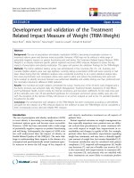
HEXORR consists of two modular components that are
capable of separately controlling movement of the fin-
gers a nd thumb (Figure 1). The de vice acts as an exos-
keleton so that the joints of the robot and the user are
aligned throughout the allowed ROM. This approach
allows for multiple points of contact between the digits
and the device, which is critical for properly controlling
the kinematic trajectory of the assisted hand move-
ments. General design criteria of this exoskeleton
included: 1) allowing the digits full ROM, 2) emulating
physiologically accurate kinematic trajectories, 3) provid-
ing adjustability to comfortably fit different hand sizes.
The component that actuates the fingers is driven by a
four-bar linkage, where the driver link base is aligned
with the MCP joints and the driver-coupler joint is
aligned with the proximal interphalangeal (PIP) joints.
We coupled the rotations of the MCP and PIP joints of
all the fingers because it has been shown that joint rota-
tions in one finger closely correlated with adjacent fin-
gers [40]. Although this study showed that the MCP-PIP
coordination pattern is slightly less than 1:1, we chose a
nearly synchronous rotation of the MCP-PIP joints to
maintain the stereotypical spiral finger tip trajectory
through 90 degrees of MCP rotation [40]. Three posi-
tions of the driver and coupler links were specified in
the design: full flexion, full extension, and an intermedi-
ate position. An infinite number of 4-bar linkages can
be designed that move the driver and coupler through
these three positions. The sol ution space of the four-bar
linkage was explored by choosing the coupler-follower
joint and graphically determining the ground point of
the follower l ink (Working Model 2D®, Design Simula-
tion Technologies, Inc., Canton, MI). This graphical
approach led to a general solution capable of generating
the desired coupler link path. Using MATLAB® (Math-
Works™, Natick, Massachusetts), custom software pro-
grams were developed to furthe r analyze and improve
the linkage design.
The goal of this analysis was to choose a four-bar
linkage design that minimizes the force required by the
fingertips to move the linkage through its ROM. We
chose this cost function to maximize the backdrivability
of the linkage. The lengths of the driver link (length of
3
rd
digit’s proximal phalanx) and the coupler link
(length of 3
rd
digit’s intermediate phalanx) are know n,
and their initial positions are set so that the hand is
fully flexed. One hundred p ossible linkage designs were
tested by generating a 2.5 × 2.5 cm grid with a resolu-
tion of 0.25 cm centered about the coupler-follower
joint position given by the graphical solution. For each
candidate coupler-follower joint lo cation, the ground
point for the follower was analytically determined that
sati sfied the three design positions of the driver-coupler
links: full flexion, full extension, and an intermediate
position. This algorithm also simulated the linkage tra-
jectories by rotating the dr iver link from full flexi on to
full extension (90°, 5° per iteration) and solved for the
corresponding positions of the other dependent links.
Finally, to assess backdrivability, two-dimensional static
force analysis was performed per iteration on each of
the generated linkage solutions. This analysis simulated
the situation when the user is attempting to rotate the
static linkage by applying a force at a certain contact
point. We focused on the contact point between the
dorsal surfaces of the DIPS and the coupler link because
it was clear from early prototypes that when the linkage
was in certain orientations, large forces were needed at
this contact point to rotate the linkage. We assumed
that resistance to rotation was due to torque at the
drive shaft caused by friction in t he geartrain, and all of
Schabowsky et al. Journal of NeuroEngineering and Rehabilitation 2010, 7:36
/>Page 3 of 16
the other joints in the linkage were frictionless. If the
torque at the drive shaft due to the applied force is lar-
ger than frictional torque, movement will occur. Thus
larger values of shaft torque from external forces would
result in higher backdrivability. This analysis assumed
that the user’ s applied force magnitude was constant
(1 N) and the direction was normal to the coupl er link
throughout the ROM. Free-body diagram analysis calcu-
lated the torque at the drive shaft needed to statically
balance this force in each linkage position. Mechanical
advantage was defi ned as the output torque at the shaft
divided by the input force magnitude. The result has
units of length and can be interpreted as an effective
moment arm between applied force and shaft torque.
The final linkage design was chosen by considering link-
age kinematic performance (e.g. no singularities, linear
coordination between driver link rotation and coupler
link rotation), maximizing mechanical advantage and
minimizing the range of the mechanical advantage pro-
file over the range of motion. In addition, solutions
were not considered if linkage solutions that were
nearby spatially had drastically different mechanical
advantage profiles. The resulting four-bar linkage design
is shown in Figure 2A and the final design performanc e
can be seen in Figure 2B.
The finger component contacts the hand at three
locations. To help stabilize the hand inside the device, a
hook and loop strap around the palm holds the hand
stationary. Also, hook and loop straps are used to attach
the proximal and intermediate phalanges to the respec-
tive robotic links. To compensate for different hand
sizes,thedriverandcouplerlinksareadjustablein
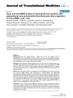
Figure 1 Pictures of a hand in HEXORR at different postures.(A) The hand flexed. (B) Palmar view of the hand in extension, highlighting
the Velcro strap arrangement. (C) The hand extended, with the thumb in pure extension and (D) the hand extended with the thumb in
abduction.
Schabowsky et al. Journal of NeuroEngineering and Rehabilitation 2010, 7:36
/>Page 4 of 16
length. Once the fing ers are comfortably strapped to the
proper robotic links, the fingers are free to perform
extension and flexion movements (Figure 1). Mechanical
stops were implemented to ensure patients are never
hyper-flexed or hyper-extended during testing sessions.
Also, to enhance comfort and reduce fatigue, a c ustom
arm rest with an elbow support was manufactured.
The thumb li nkage design wa s synthesized using simi-
lar methods as those used for the finger linkage (Figure
2C). The model simplifies the motion o f the thumb’ s
metacarpal and proximal phalanges as a single driver
link that rotates about the carpometacarpal joint
(CMC). The driver-coupler j oint is centered at the
thumb IP. The driver-coupler coordination pattern is
synchronous, resulting in approximately 20 and 90
degrees of rotation in the CMC and IP joints, respec-
tively. Additional analysis determined that this move-
ment pattern required the coupler-follower joint to
move in a nearly straight line. Therefore, the coupler-
follower point was placed on a linear bearing, resulting
in a crank and slider mechanism. The thumb’ sdistal
phalanx is attached to the mechanism’ scouplerlink
with a hook and loop strap. As the CMC joint rotates
about the driver ground joint, the thumb’s metacarpal
bone and proximal phalanx closely follow the motion of
the driver link. Alt hough it was not necessary to imple-
ment in this study, it is possible to also strap the proxi -
mal phalanx to the driver link (not shown) to better
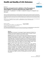
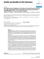
Figure 2 Linkage motion simulation and force analysis.(A) Finger and (C) thumb motion simulation with the initial flexion position linkage
configurations bolded and the thumb linkage’s slider shaft is shown as a dotted line (green). Finger and thumb images are superimposed at the
flexed and extended positions. (B) For the fingers, mechanical advantage is output torque at the drive shaft joint that is aligned with the MCP
divided by the input force located at the contact point between the linkage and the DIP joints. (D) For the thumb, mechanical advantage is the
torque at the CMC joint divided by the force at the thumbtip. The x-axis of these plots is the angle of the driver link relative to the fully flexed
initial position.
Schabowsky et al. Journal of NeuroEngineering and Rehabilitation 2010, 7:36
/>Page 5 of 16
control the IP and CMC joints. The base of the thumb
device is highly adjustable. The mechanism can ascend
and descend vertically along a slotted shaft to accommo-
date varied hand sizes. The base can also be adjusted
(tilted and rotated) to increase or decrease the amount
of thumb abduction/adduction involved in the exercises.
Similar to the finger component, the thumb component
allows a large ROM. The final design performance can
be seen in Figure 2D.
Control Hardware and Sensors
The finger four-bar linkage is driven by a direct current,
brushless motor (Maxon Motors, Fall River MA) in ser-
ies with a planetary gear head (reduction ratio 74:1,
Maxon Motors, Fall River MA) that is capable of out-
putting a continuous torque of 9.8 Nm. For position
sensing, a digital optical encoder (resolution of 0.002
degrees) is attached to the e nd of the motor. A second
encoder is placed inline between the linkage and the
gear head (resolution of .04 degrees). A torque sensor
(TRT-200, Transducer Techniques, Temecula CA) is
positioned between the motor and the linkage; that is
capable of measuring up to 33 Nm of f inger flexion/
extension torque at a resolution of 0.02 Nm and can
serve as both a patient assessment tool and as online
feedback to be used in novel therapy techniques.
The thumb component’scrankisdrivenbyaFHA
mini-series alternating current servo actuator (Harmonic
Drive LLC, Peabody, MA) with a harmonic drive gear
head (reduction ratio of 100:1 , max continuous torque
of 11 Nm). This actuator was chosen because of its
small housing (60 × 59 × 56 mm) that ensures the
thumb component easily fits underneath the finger com-
ponent. A digital encoder measures shaft angle (resolu-
tion of .0005 degrees). A torque sensor (Transducer
Techniques, TRT-200) is positioned between the AC
servo actuator and the crank.
A single electronic box houses the hardware that con-
trols the motors and interfaces with the torque and
position sensors. The motors are controlled by servo
drivers operated in torque control mode ( Maxon
Motors, 4-Q-DC; Accelnet, ACP-055-18). A custom kill-
switch can be used to shut down power to both motors.
Analog signals from the torque sensors are collected by
a data acquisition board (Measurement Computing,
PCI-DAS1200). Encoder signals were sampled with a
PCI-QUAD04 quadrature encoder board (Measurement
Computing).
Software and Compensation Algorithms
The exoskeleton is controlled with custom software pro-
grams developed using the xPC Tar get® and Stateflow®
toolboxes in MATLAB®. Because strok e survivors have
weakness in the impaired hand, considerable effort was
placed on decreasing the torque nee ded to open and
close one’ s hand inside HEXORR. This was accom-
plished by increasing the backdrivability of the exoskele-
ton. Similar to the work outlined in a recent technical
note [41], we developed algorithms to model and com-
pensate for the weight and friction (both static and
kinetic) of the exoskeleton.
Gravity compensation was modeled by identifying the
motor output (current) required t o move the linkages
throughout the entire ROM at a slow, constant velocity
(5°/sec) in both the exte nsion and flexion directions.
This produced a current vs. angle profile for each di rec-
tion. At 1° increments, the values from the extension
and flexion profiles were averaged to develop a gravity
compensation motor output profile. An interpo lation/
extrapolation table was created using these data to pro-
vide accur ate gravity compensation throughout the full
movement range of the linkage.
Kinetic friction compensation was modeled through
viscosity coefficients. These coefficients were calculated
by moving the exoskeleton at different, constant veloci-
ties and subtracting the motor output required for grav-
ity compensation. The required motor output (current)
increases linearly with velocity (R
2
> 0.99) and can be
accurately modeled with linear regression equations.
These linear models were used to predict and counter
velocity-dependent friction. Static friction was estimat ed
by the motor output required to in itiate movement after
compensating for gravity. This motor output was
reduced by a factor of 0.85 to ensure that the linkage
does not move when no other forces are applied to the
exoskeleton. For thi s system, increasing the gain beyond
0.85 resulted in over-compensation and caused the
robot to move.
ThebackdrivabilityofHEXORRwastestedbyasub-
ject moving the exoskeleton at a constant velocity (40°/
sec) with and without compensation. Without any com-
pensation, the torque requiredtoextendthelinkages
ranged from 0.45 Nm to 0.8 Nm. H owever, with weight
and friction compensation, the required torque was
reduced to values no greater than 0.2 Nm and remained
constant throughout the movement. On average, the
weight and friction compensation algorithms increased
HEXORR’s backdrivability by more than 66%.
Safety Measures
Because this exoskeleton is a rehabilitation device
designed to interact with individuals that have impaired
hands, it is imperative to incorporate both hardware and
software safety mechanisms. Me chanical safety stops are
positioned so that the fingers and the thumb cannot be
hyper-extended when users perform hand movements
inside of HEXORR. A kill switch is also impleme nted so
that the experimenter can shut down both motors
Schabowsky et al. Journal of NeuroEngineering and Rehabilitation 2010, 7:36
/>Page 6 of 16
simultaneously at any time. HEXORR also has software
ROM stops. Before each training session, the experi-
menter man ually extends the subject’ sfingersand
thumb asking if the subject feels any pain and also care-
fully watches for any expressions of discomfort. If the
subject cannot tolerate full extension, the expe rimenter
can limit the device’s ROM via the graphi cal user inter-
face. The experimenter can also limit the velocity of the
linkages through software controls. Finally, saturation
levels are used to ensure that the motor command
never exceeds a predetermined threshold.
Experimental Setup
Nine right-ha nded, neurologically intact subjects, (aged
23-57 years, mean = 32 ± 12), and five stroke subjects
(aged 33-61 years, mean = 53 ± 12) participated in this
experiment. All stroke subjects had right hand impair-
ments and handedness was assessed with the ten item
Edinburgh inventory [42]. Only subjects that received a
laterality quotient of 80% or greater were admitted into
this study. All subjects signed an inform ed consent form
prior to admission to the study. All protocols were
approved by the Internal Review Board of the MedStar
Research Institute.
This pilot study focused on stroke s ubjects with mild
to moderate motor function impairment. For stroke
subjects, inclusion criteria required a first ischemic or
hemorrhagic stroke occurring more than 6 months prior
to acceptance into the study, and trace ability to extend
the MCP and PIP joints. Exclusion criteria included
excessive pain in any joint of the affected extremity that
could limit the ability to cooperate with the protocols,
uncontrolled medica l problems as judged by t he project
therapist, and a full score on the hand and wrist sections
of the Fugl-Meyer motor function test [43].
Before using the robot, stroke subjects were clinically
evaluated (Table 1). Upper extremity movement impair-
ments were evaluated with the Action Research Arm
Test [44] and the upper extremity Fugl-Meyer Assess-
ment. Muscle tone was measured at the elbow, wrist
and fingers with the Modified Ashworth Scale [45].
Subjects were seated in a chair and the ir right hand
was placed inside HEXORR. The forearm was placed on
an arm rest in t he neutral position and the table was
adjusted so that the elbow was flexed at 90° and the
shoulder elevated approximately 45°. An elbow support
pad wa s placed on the posterior side of the upper arm
to minimize shoulder retraction and extension. For each
subject , the lin kages of the exoskeleton were adjusted to
fit the size of the hand. The hand was strapped to the
device and subjects performed hand movements inside
HEXORR for about 30 to 60 minutes. A real-time com-
puter display of their hand’s position was availabl e, but
in most cases the subjects watched their own hands dur-
ing the movements.
Experimental Tasks
Unimpaired subjects performed tasks specifically
designed to evaluate HEXORR’s ability to prod uce phy-
siologically accurate hand movements throughout the
five digits’ ROM. For these tasks, the subjects wore the
wireless CyberGlove II® (CyberGlove Systems, San Jose,
Table 1 Stroke Clinical Assessments
Measure All subjects Subject 1 Subject 2 Subject 3 Subject 4 Subject 5
n5
Age (year) 59 61 51 62 33
Gender 1F/4M
Time post-stroke (months) 14 19 12 300 34
Action Research Arm Test (total score = 57) 22.4 ± 3.2 20 21 21 22 28
Grasp (total score = 18) 6.2 ± 1.1 6 5 6 6 8
Grip (total score = 12) 5.2 ± 1.3 4 4 5 6 7
Pinch (total score = 18) 6.2 ± 0.45 6 6 6 6 7
Gross Movement (total score = 9) 4.8 ± 1.1 4 6 4 4 6
Arm Motor Fugl-Meyer score (total score = 66) 34 ± 7 35 34 35 23 43
Proximal arm subportion (total score = 42) 22 19 20 9 25
Hand/wrist subportion (total score = 24) 12 13 14 13 15
Coordination/Speed (total score = 6) 1 2 1 1 3
Modified Ashworth Spasticity Scale (unimpaired = 0) 1.7 ± 0.3 1 + 1 + 2 1 + 2
Elbow 1 + 1 + 2 1 + 2
Wrist 1 + 1 + 2 1 + 1 +
Finger 1 + 1 + 2 1 + 1 +
Results are mean ± standard error. Subjects received clinical assessment prior to using the robotic device. This pilot study was not intended to provide therapy,
so no follow-up assessment was conducted.
Schabowsky et al. Journal of NeuroEngineering and Rehabilitation 2010, 7:36
/>Page 7 of 16
CA) during movements both inside of and outside of
the device. This glove features three flexion sensors
per finger, four abduction sensors, a palm-arch sensor,
and sensors to measure wrist flexion a nd abduction.
Subjects performed five hand extension/flexion move-
ments throughout the full active ROM outside of
the device, five continuous passive extension/flexion
movements (finger encoder rotation 0° to 80°, thumb
encoder rotation 0° to 20°) in HEXORR, and 10 active-
unassisted hand movements inside of the device.
Because HEXORR’ s mechanical safety stops did not
allow for hyperextension, subjects were asked not to
hyperextend their hand’ s digits while performing
extension movements outside of the device. During the
unassisted movements in the device, the motors pro-
vided previously described gravity and friction
compensation.
Stroke subjects performed hand movements within
HEXORR during three different modes: continuous
passive movements, active-unassisted extension/flexion
and active force-assisted extension/flexion. During the
five passive movements, subjects were asked to relax
their hand fully as the motors moved their digits
throughout a comfortable ROM pre-determined by an
occupational therapist (a ll stroke subjects tolerated full
extension of the finger s and thumb). Then, subjec ts
were asked to perform five active-unassisted move-
ments at a self-determined speed. During these move-
ments, motors provided only weight and friction
compensation. This mode was also designed to ‘ catch’
any involuntary flexion movements during an intended
extension movement. Any unintended flexion move-
ment was halted by the motors, and the exoskeleton
was held in place. Subjects were given three a ttempts
to further extend their digits before the experimenter
prompted the motors to finish the extension move-
ment. Finally, subjects performed movements during
an active force-assisted mode, where subjects received
assistance during extension movements. Using data
from the previous passive stretching exercises, the
mean motor current required to passively extend the
subject’ s digits were tabulated into a position depen-
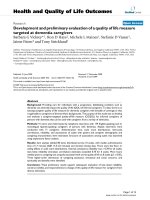
dent assistance profile. Figure 3A displays an example
of the motor current required to passively stretch a
stroke subject’ s hand. This profile was scaled by an
adjustable gain and delivered feedforward during the
movements. After each extension attempt, the gain
was reduced from 1 by increments of 0.2 until the sub-
jects indicated that they were actively opening their
hand. Once a proper gain was found, subjects o pened
andclosedtheirhandfivetimes with this assistance.
Figure 3B illustrates a block diagram to further
describe the active-unassisted and active force-assisted
conditions.
Data Analysis
Custom software recorded the positi ons and t orques
from the robot (f
S
= 1 kHz). The encoder signals were
digitally differentiated and low pass Butterworth-filtered
(f
C
= 30 Hz) to yield angular velocity. Torque sensor
signals were filtered (f
C
= 15 H z) and biases were
removed prior to data analysis. Without a hand in the
exoskeleton, the linkages were moved slow ly (1°/second)
throughout the R OM and the torques were recorded.
These torque values were interpolated, averaged and
used as positio n dependent torque sensor bias values.
CyberGlove II® data was separately collected using the
manufacturer’s data acquisition software (f
S
=100Hz).
Calibration of the CyberGlove sensors was performed
based on the manufacturer’ s recommendations. The
initiation and cessation of hand movements were
defined as 5% of the maximum angular velocity.
For the unimpaired subjects, digit ROM and join t-pair
coordination were investigated with the CyberGlove II®
data. Active ROM analysis con sisted of calcula ting the
difference between the maximum extension and flexion
angles in all joints. Joint-pair coordination was assessed
for t he 1
st
and 3
rd
digits under two conditions: outside
and inside HEXORR. For the 1
st
digit, CMC-MCP and
MCP-IP joint-pairs were analyzed, and for the 3
rd
digit,
MCP-PIP and PIP-DIP joint-pairs were considered.
These pairs were plotted (x axis: proximal joint, y axis:
distal joint) and modeled by linear regression. Linearity
was measured with the coefficient of determination (R
2
).
For the stroke subjects, the ROM and torque produc-
tion of the fingers and thumb were compared in the
active-unassisted and active force-assisted conditions.
The ROM analysis was similar to the unimpaired sub-
ject ROM calculation, but by using HEXORR’s encoders
instead of the CyberGlove II®. Average torque values
were calculated to investigate the extent of the subjects’
voluntary participation during extension movements.
Only torque values during exoskeleton movement were
considered and torques produced during a pause in
motion, caused by hand flexion during a designated
extension movement, were removed from the analysis.
By convention, posi tive torque values indi cate torque in
the extension direction. Therefore, i f the average torque
during an extension movement was positive, we con-
cluded that the subject performed an active extension
movement. Accord ingly, if t he average torque value was
neg ative, then the provided assistance was too high and
the robot pulled the digits open.
Unimpaired subjects’ finger active ROM analysis was
performed by repeated measures ANOVA with two
within subject factors: condition (2: inside and outside
of HEXORR) and joint (15 separate joints). All other
metrics were statistically evaluated by a paired, two-
tailed student t-test.
Schabowsky et al. Journal of NeuroEngineering and Rehabilitation 2010, 7:36
/>Page 8 of 16
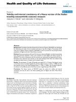
Figure 3 Assistance condition illustrations.(A) An example o f the moto r current neede d to passi vely stretch a stroke subject’sfingers,
compared to gravity compensation. X-axis is the MCP extension angle relative to the fully flexed position. (B) Block diagram of the
compensation provided for the active-unassisted and active-force assisted conditions. Stiction is provided when -0.1°/sec ≤ angular velocity ≤ +0.
1°/sec. Otherwise, kinetic friction compensation is provided.
Schabowsky et al. Journal of NeuroEngineering and Rehabilitation 2010, 7:36
/>Page 9 of 16
Results
Figure 4 illustrates the unimpaired subjects’ active ROM
(mean ± standard error) under the three conditions:
hand movements outside of the exoskeleton, passive
stretching and active-unassisted movements inside the
exoskeleton. For many of the joints, there were no sig-
nificant differences between active movements per-
formed inside and outside of the device. Paired t-test
analysis showed no significant differences in thumb
active ROM. However, the condition factor was signifi-
cant (F
(1,8)
= 11.6, P = 0.009) for finger active ROM.
Post-hoc analysis was performed w ith Bonferroni cor-
rec ted paired t-tests. For MCP rotation (Figure 4A), the
4
th
(difference = 19°, P = 0.017) and 5
th
(difference =
17°, P = 0.015) digits rotated significantly less inside of
HEXORR than outside of the device. The PIP rotation
(Figure 4B) of the 5
th
digit was also significantly less
inside of the exoskeleton compared to movements made
outside of the device (difference = 23°, P = 0.003). The
remaining 12 joints had no significant active ROM dif-
ferences between movements made inside and outside
of HEXORR.
For the 1
st
and 3
rd
digits of the hand, mean joint-pair
coordination comparisons between active-unassisted
extension movements inside HEXORR and those made
outside of the device were compared. An example of a
subject ’s joint-pair coordination can be seen in Figure 5.
For every subject, the coordination between joint pairs
for both the 1
st
and 3
rd
digits was highly linear (R
2
≥
0.957) both inside and outside of HEXORR. For the fin-
gers, the average slopes of the MCP-PIP regressions for
movements made inside and outside of the device were
1.31 ± 0.24 and 1.17 ± 0.14, respectively and the mean
PIP-DIP regression slopes were 0.21 ± 0.1 for move-
ments w ithin HEXORR and 0. 15 ± 0.12 for movements
outside of the device. For the thumb, the mean slopes of
the C MC-MCP regressions for movements made insid e
and outside of the device were 1.36 ± 0.43 and 1.09 ±
0.38, respectively and the mean MCP-IP regression
slopes were 1.99 ± 0.46 for movements within HEXORR
and 2.29 ± 0.63 for movements outside of the device.
Also, paired t-tests indicated n o significant dif ferences
between the s lopes of the joint-pa ir coordination plots
for the 1
st
(P > 0.143) and 3
rd
(P > 0.171) digits. This
indicates that performing extension movements with the
hand inside HEXORR emulates physiologically accurate
extension trajectories.
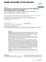
Figure 6 summarizes each stroke subject’ sperfor-
mance during both the active-unassisted and active
force-assisted conditions. Active ROM varied widely
on an individual basis (Figures 6A and 6C). The e xtent
of finger extension during the active-unassisted condi-
tion ranged from 5° to full extension (80°) at the MCP,
and thumb ROM varied between approximately 1° to
16° and 5° t o 64° for the CMC and IP, respectively.
Average extension torque correlated positively with
extension ROM (Figures 6B a nd 6D). Generally the
higher the average torque, the greater the active ROM.
The displayed active force-assisted condition values
were generated by averaging 5 extension movements
while providing assistance with a gain of 0.6. Note that
mean thumb extension torques during the active force-
assisted condition for Subjects 4 and 5 we re negative.
This indicates that the provided assistance pulled the
thumb open. Accordingly, the thumb data for these
two subjects were not considered in the group analysis
below. With assistance, the mean active extension
ROM increased by 17° ± 4.2° (excluding Subject 1) for
the fingers’ MCP and PIP; the thumb’ sCMCandIP
increased by 2.6° ± 1.2° and 11.7° ± 3° respectively.
The provided assistance increased f inger ROM by 43 ±
5%, while reducing the required finger extension tor-
que by 22 ± 4%; thumb ROM was increased by 24 ±
6%, while the required thumb e xtension torque was
reduced by 30 ± 5%.
During both the active-unassisted and active force-
assisted conditions, any involuntary flexion movement
was halted during a designated extension movement and
the stroke subjects were able to try to extend their digits
further from this point. Providing this ‘ flexion catch’
greatly increased the active extension ROM for both the
fingers and the thumb. On average, the flexion catch
feature increased the active ROM by approximately 20°
±5°forthefingers’ MCP and PIP; the thumb’ sCMC
and IP were increased by 5° ± 3° and 22° ± 6° respec-
tively. An example of a stroke s ubject taking advantage
of the ‘flexion catch’ to increase his fingers’ active ROM
during the active-unassisted condition can be seen in
Figure 7.
Discussion
We developed a novel e xoskeleton to provide hand
motor therapy to stroke patients and we conducted a
pilot study to test our initial design goals and to evalu-
ate an active force-assistance therapy mode. HEXORR
consists of two modular components that are capable of
separately controlling the fingers and thumb. This exos-
keleton accommodates virtually any hand size and pro-
vides extension/flexion assistance for all f ive digits of
the hand through their entire ROM. Our compensation
algorithms account for gravity and friction, greatly
increasing the device’s backdrivability. The main results
of our pilot study indicate that, overall, HEXORR was
successful in allowing full ROM of the fingers and
thumb. Also, the guidance of the linkages maintained
physiologically accurate inter-joint coordination
Schabowsky et al. Journal of NeuroEngineering and Rehabilitation 2010, 7:36
/>Page 10 of 16
Figure 4 Unimpaired subjects’ ROM. T he mean values of the unimpaired subjec ts’ (A)MCP,(B)PIPand(C) DIP joints for digits 2-5 under 3
conditions: passive stretch, active-unassisted movements inside HEXORR and active movement outside of the exoskeleton. For the first digit, the
joints are the (A) CMC, (B) MCP and (C) IP. Twelve of the fifteen tested joints showed no significant ROM differences between active movements
outside and inside HEXORR.
Schabowsky et al. Journal of NeuroEngineering and Rehabilitation 2010, 7:36
/>Page 11 of 16
throughout the movements. The stroke subjects were
capable of active extension during the active-unassisted
condition and the active force-assisted condition suc-
cessfully increased the stroke subject’ sactiveROM
while maintaining user control of the movements.
Testing with unimpaired subjects showed that for 12
of the 15 tested hand joints there were no significant
ROM differences between hand movements performed
inside and outside of HEXORR. Three joints rotated sig-
nificantly less inside HEXORR, the 4
th
and 5
th
digits ’
MCP and the 5
th
digit’ s PIP. We believe that the
mechanical stop intended to avoid finger hyper-flexion
caused the reduction in the two MCP joints’ ROM. This
stop was designed to position the 3
rd
digit’s MCP at 90°
of flexion (proximal phalanx orthogonal to the palm).
Because the machine-hand interface was flat, all of the
fingers’ proximal phalanges were strapped into this posi-
tion, resulting in slight misalignment of the MCPs in
the shorter digits. Our safety backstop did not allow
flexion to 90° in these two MCP joints, thereby reducing
their total ROM. It is particularly dif ficult to strap the
intermediate phalanx of the 5
th
digit to the robot
because of diffe rences in digit lengths, and this resulted
in a reduced ROM for the 5
th
digit’s PIP. A simple solu-
tion calls for a slight redesign so that the 5
th
digit’spha-
langes can be individually strapped to the linkage
thereby potentially increasing these joints’ ROM. The
current design of HEXORR is generally successful in
producing full ROM of the hand’s digits and with a cou-
ple of simple design changes this device will al low full
ROM for all of the hand’s digits.
The stroke subjects were capable of actively extending
the hand’ s digits within HEXORR during the active-
unassisted condition. Stroke subjects’ ROM varied
widely and correlated w ith their impairment level, as
judged by clinical assessment. For instance, Subject 4
performe d the worst in the Fugl-Meyer assessment and,
accordingly, had the lowest active ROM within
Figure 5 Joint-pair coordination plots for an unimpaired subject. Plots display the 1
st
digit (A) CMC-MCP pair (B) MCP -IP pair and 3
rd
digit
(C) MCP-PIP pair and (D) PIP-DIP pair (mean ± standard error). Paired t-tests indicate no significant differences between trajectories performed
inside and outside of the exoskeleton. All joint angles are measured relative to the initial fully flexed posture of the hand.
Schabowsky et al. Journal of NeuroEngineering and Rehabilitation 2010, 7:36
/>Page 12 of 16
HEXORR. All subjects produced torques in the exten-
sion direction showing that the activ e-unassi sted condi-
tion did not provide overcompensation for gravity and
friction. Torque sensor data showed that many subjects
unintentionally activated their flexors during extension
movements; this typically results in flexing the hand ’s
digits. The ‘flexion ca tch’ feature prevented unintended
flexion movements during a designated extension move-
ment, a nd increased the active ROM by approximately
35%. This mechanism is useful because it allows subjects
to focus on individually activating their extensor mus-
cles at positions they are normally incapable of reaching.
Increasing the digits’ active ROM promotes neural acti-
vation by cre ating a larger afferent signal to the brain
sensorimotor areas [46].
The assistance provided during the active force-
assisted condition further increased the stroke sub-
jects’ hand’ s active R OM. Similar to a previous study
[47], we designed this condition so the provided assis-
tance was dependent on the motor current required
to passively stretch the subject’s digits. This approach
directly counters muscle tone, one of the neural
mechanisms shown to impede hand extension [6].
Providing assistive forces in the extension direction
also inherently helps to counteract the muscle weak-
ness imbalance between the extensor and flexor mus-
cles [9,10]. Generally, torque data show ed that, even
with assistance, stroke subjects still actively controlled
the movements with extension torque. For Subjects 4
and 5, the average thumb torque values were negative,
indicating that the assistive forces pulled the thumb
open. This is not ideal because it has been shown
that providing too much assistance can encourage
patients to decrease their own physical effort during
therapy [48,49], and impede motor learning [50]. It
appears that using the optimal gain in this algorithm
will be critical for effective therapy, but the optimal
gain will vary across subjects. Therefore, a more
sophisticated algorithm is needed to customize the
assistance level to the subject. One potential approach
is developing an adaptive controller that can adjust
the gain of the provided assi stance on eac h trial based
Figure 6 Stroke subject performance.(A) Finger MCP ROM and (B) mean torques and (C) thumb CMC ROM and (D) mean torques are shown
for both the active-unassisted and active force-assisted conditions. The provided assistance increased finger active ROM by 43% and reduced
finger extension torque by 22%. For the thumb, active ROM was increased by 24%, reducing thumb extension torque by 30%. For the thumb,
the mean torque for Subject 4 and 5 were negative. This indicates that the assistance forces were too high and extended the thumb
Schabowsky et al. Journal of NeuroEngineering and Rehabilitation 2010, 7:36
/>Page 13 of 16
on past subject performance [51,52]. This approach
has proven successful in prompting both short-term
and long-term motor learning while reducing perfor-
mance error [53,54]. In our application, the adaptive
algorithm would use kinematic and torque data from
previous trials to adjust the assistance gain to maxi-
mize extension ROM while maintaining user control
by requiring active extension torque to complete the
movements.
Some of the limitations of the HEXORR design can be
addressed in future work. Controlling the palmar arch is
important in object manipulation and it has been shown
that stroke subjects exhibit delayed and i ncomplete pal-
mar arch modulation during a grasping task [55]. Our
device currently has a flat support for attaching to the
dorsal surface of the hand and does not assist palmar
arch modulation. A potential solution would be selecting
a more flexible, pre-shaped (concave) material for the
hand support that would allow palmar arch modulation.
Similarly, inability to abduct/adduct at the MCP joint
can be addressed in future designs by incorporating pas-
sive DOFs into the mechanism that allow this motion if
the subject is capable. Finally, the cu rrent design cannot
be used with left hands. We are working on modifica-
tions to address this that involve the ability to q uickly
replace the linkages with mirror-image versions
designed for the left hand.
Conclusions
Our pilot study shows that this device is capable of
moving t he hand’s digits through the entire ROM with
physiologically accurate trajectories. We tested stroke
patients with mild to moderate motor function impair-
ment who had at least trace ability to extend the fingers.
These subjects received the device intervention well and
were able to actively extend and flex their digits inside
of HEXORR. O ur active force-assisted condition was
suc cessful in increasing the subjects’ ROM while gener-
ally promoting active participation. We a re currently
developing a more sophisticated adaptive active-assis-
tance algorithm to provide the optimal assistance level
and prof ile that promotes motor learning while continu-
ing to challenge the subject’s abilities.
Acknowledgements
We would like to thank Dr. Joe Hidler for his contributions to the design of
HEXORR and manuscript review. We would also like to thank Rex and Ashley
Lewis of Turnkey Automation, Inc. (Raymond, ME) for manufacturing
HEXORR. Funding for this work provided by the U.S. Army Medical Research
and Materiel Command (W81XWH-05-1-0160), and the Department of
Veterans Affairs (Merit Review #B4719R)
Author details
1
Center for Applied Biomechanics and Rehabilitation Research (CABRR),
National Rehabilitation Hospital, 102 Irving Street, NW Washington, DC
20010, USA.
2
Veterans Affairs Medical Center, 50 Irving Street NW (151),
Washington, DC 20422, USA.
3
Department of Biomedical Engineering,
Catholic University, 620 Michigan Ave., NE Washington, DC 20064, USA.
4
Neuroscience Research Center, National Rehabilitation Hospital, 102 Irving
Street, NW, Washington, DC 20010, USA.
Authors’ contributions
CNS participated in the design of HEXORR, data collection, analysis and
interpretation, and manuscript preparation. SBG participated in data
acquisition and analysis. RJH participated in subject recruitment and clinical
assessment of stroke subjects. PSL participated in the design of HEXORR,
data interpretation and manuscript preparation. All authors have read and
approved the final manuscript.
Competing interests
The authors declare that they have no competing interests.
Received: 27 November 2009 Accepted: 28 July 2010
Published: 28 July 2010
References
1. Stroke Statistic: 2009 Update. Centennial, CO: National Stroke Association
2009.
2. Rathore S, Hinn A, Cooper L, Tyroler H, Posamond W: Characterization of
incident stroke signs and symptoms: findings from the atherosclerosis
risk in communities study. Stroke 2002, 33:2718-2721.
3. Heart Disease and Stroke Statistics: 2005 Update. Dallas, Tex: American
Heart Association 2005.
4. Duncan PW, Bode RK, Min Lai S, Perera S: Rasch analysis of a new stroke-
specific outcome scale: the Stroke Impact Scale. Arch Phys Med Rehabil
2003, 84(7):950-963.
5. Kwakkel G, Kollen BJ, an der Grond J, Prevo AJ: Probability of regaining
dexterity in the flaccid upper limb. The impact of severity of paresis and
time since onset in acute stroke. Stroke 2003, 34:2181-2186.
Figure 7 Extension movement performed by Subject 2. Flexion
motion was halted by the motors and the subject was able to relax
the flexors and then further extend the hand’s digits.
Schabowsky et al. Journal of NeuroEngineering and Rehabilitation 2010, 7:36
/>Page 14 of 16
6. Kamper DG, Rymer WZ: Quantitative features of the stretch response of
extrinsic finger muscles in hemiparetic stroke. Muscle Nerve 2000,
23(6):954-961.
7. Kamper DG, Harvey RL, Suresh S, Rymer WZ: Relative contributions of
neural mechanisms versus muscle mechanics in promoting finger
extension deficits following stroke. Muscle Nerve 2003, 28(3):309-318.
8. Landau WM, Sahrmann SA: Preservation of directly stimulated muscle
strength in hemiplegia due to stroke. Arch Neurol 2002, 59(9):1453-1457.
9. Kamper DG, Fischer HC, Cruz EG, Rymer WZ: Weakness is the primary
contributor to finger impairment in chronic stroke. Arch Phys Med Rehabil
2006, 87(9):1262-1269.
10. Lum PS, Burgar CG, Shor PC: Evidence for strength imbalances as a
significant contributor to abnormal synergies in hemiparetic subjects.
Muscle Nerve 2003, 27(2):211-221.
11. Cruz EG, Waldinger HC, Kamper DG: Kinetic and kinematic workspaces of
the index finger following stroke. Brain 2005, 128(Pt 5):1112-1121.
12. Kamper DG, Rymer WZ: Impairment of voluntary control of finger motion
following stroke: role of inappropriate muscle coactivation. Muscle Nerve
2001, 24(5):673-681.
13. Carey JR, Kimberley TJ, Lewis SM, Auerbach EJ, Dorsey L, Rundquist P,
Ugurbil K: Analysis of fMRI and finger tracking training in subjects with
chronic stroke. Brain 2002, 125(Pt 4):773-788.
14. Carey JR, Durfee WK, Bhatt E, Nagpal A, Weinstein SA, Anderson KM,
Lewis SM: Comparison of finger tracking versus simple movement
training via telerehabilitation to alter hand function and cortical
reorganization after stroke. Neurorehabil Neural Repair 2007, 21(3):216-32.
15. Krebs HI, Hogan N, Volpe BT, Aisen ML, Edelstein L, Diels C: Overview of
clinical trials with MIT-MANUS: a robot-aided neuro-rehabilitation facility.
Technol Health Care 1999, 7(6):419-423.
16. Burgar CG, Lum PS, Shor PC, Machiel Van der Loos HF: Development of
robots for rehabilitation therapy: the Palo Alto VA/Stanford experience.
J Rehabil Res Dev 2000, 37(6):663-673.
17. Reinkensmeyer DJ, Kahn LE, Averbuch M, McKenna-Cole A, Schmit BD,
Rymer WZ: Understanding and treating arm movement impairment after
chronic brain injury: progress with the ARM guide. J Rehabil Res Dev
2000, 37(6):653-662.
18. Hesse S, Schulte-Tigges G, Konrad M, Bardeleben A, Werner C: Robot-
assisted arm trainer for the passive and active practice of bilateral
forearm and wrist movements in hemiparetic subjects. Arch Phys Med
Rehabil 2003, 84(6):915-920.
19. Nef T, Mihelj M, Riener R: ARMin: a robot for patient-cooperative arm
therapy. Med Biol Eng Comput 2007,
45(9):887-900.
20. Aisen ML, Krebs HI, Hogan N, McDowell F, Volpe BT: The effect of robot-
assisted therapy and rehabilitative training on motor recovery following
stroke. Arch Neurol 1997, 54:443-446.
21. Volpe BT, Krebs HI, Hogan N, Edelsteinn L, Diels CM, Aisen ML: Robot
training enhanced motor outcome in patients with stroke maintained
over 3 years. Neurology 1999, 53(8):1874-1876.
22. Lum PS, Burgar CG, Shor PC, Majmundar M, Van der Loos M: Robot-
assisted movement training compared with conventional therapy
techniques for the rehabilitation of upper-limb motor function after
stroke. Archives of Phys Med Rehabil 2002, 83(7):952-959.
23. Fasoli SE, Krebs HI, Stein J, Frontera WR, Hughes R, Hogan N: Robotic
therapy for chronic motor impairments after stroke: Follow-up results.
Arch Phys Med Rehabil 2004, 85(7):1106-1111.
24. Kahn LE, Rymer WZ, Reinkensmeyer DJ: Adaptive assistance for guided
force training in chronic stroke. Conf Proc IEEE Eng Med Biol Soc 2004,
4:2722-2725.
25. Lum PS, Burgar CG, Van der Loos M, Shor PC, Majmundar M, Yap R: MIME
robotic device for upper-limb neurorehabilitation in subacute stroke
subjects: A follow-up study. J Rehabil Res Dev 2006, 43(5):631-642.
26. Dovat L, Lambercy O, Gassert R, Maeder T, Milner T, Leong TC, Burdet E:
HandCARE: a cable-actuated rehabilitation system to train hand function
after stroke. IEEE Trans Neural Syst Rehabil Eng 2008, 16(6):582-91.
27. Dovat L, Lambercy O, Salman B, Johnson V, Milner T, Gassert R, Burdet E,
Leong TC: A technique to train finger coordination and independence
after stroke. Disabil Rehabil Assist Technol 2010, 5(4):279-87.
28. Bouzit M, Burdea G, Popescu G, Boian R: The Rutgers Master II-New
Design force-feedback glove. IEEE/ASME Trans Mechatronics 2002,
12(4):399-407.
29. Boian R, Sherman A, Han C, Merians A, Burdea G, Adamovich S, Recce M,
Tremaine M, Poizner H: Virtual-reality-based post-stroke hand
rehabilitation. Stud Health Technol Inform 2002, 85:64-70.
30. Merians AS, Jack D, Boian R, Tremaine M, Burdea GC, Adamovich SV,
Recce M, Poizner H: Virtual reality-augmented rehabilitation for patients
following stroke. Phys Ther 2002, 82(9):898-915.
31. Lambercy O, Dovat L, Gassert R, Burdet E, Teo CL, Milner T: A haptic knob
for rehabilitation of hand function. IEEE Trans Neural Syst Rehabil Eng 2007,
15(3):356-66.
32. Masia L, Krebs HI, Cappa P, Hogan N: Design and Characterization of
Hand Module for Whole-Arm Rehabilitation Following Stroke. IEEE ASME
Trans Mechatron 2007, 12(4):399-407.
33. Adamovich SV, Fluet GG, Mathai A, Qiu Q, Lewis J, Merians AS: Design of a
complex virtual reality simulation to train finger motion for persons with
hemiparesis: a proof of concept study. J Neuroeng Rehabil 2009, 17:6-28.
34. Wege A, Zimmerman A: Electromyography sensor based control for a
hand exoskeleton. Proceedings of the 2007 IEEE ICRB 1470-1475.
35. Fischer HC, Stubblefield K, Kline T, Luo X, Kenyon RV, Kamper DG: Hand
rehabilitation following stroke: a pilot study of assisted finger extension
training in a virtual environment. Top Stroke Rehabil 2007, 14(1):1-12.
36. Takahashi C, Der-Yeghiaian L, Le V, Cramer SC: A robotic device for hand
motor therapy after stroke. Proceedings of IEEE 9th International Conference
on Rehabilitation Robotics: Frontiers of the Human-Machine Interface Chicago,
Illinois 2005, 17-20.
37. Takahashi CD, Der-Yeghiaian L, Le V, Motiwala RR, Cramer SC: Robot-based
hand motor therapy after stroke. Brain 2008, 131:425-437.
38. Koeneman EJ, Schultz RS, Wolf SL, Herring DE, Koeneman JB: A pneumatic
muscle hand therapy device. Conf Proc IEEE Eng Med Biol Soc 2004,
4:2711-2713.
39. Kawasaki H, Ito S, Ishigure Y, Nishimoto Y, Aoki T, Mouri T, Sakaeda H,
Abe M: Development of a Hand Motion Assist Robot for Rehabilitation
Therapy by Patient Self-Motion Control. IEEE Proceedings of 10th ICORR
2007, 234-240.
40. Kamper DG, Cruz EG, Siegel MP: Stereotypical fingertip trajectories during
grasp. J Neurophysiol 2003, 90:3702-3710.
41. Nef T, Lum P: Improving backdrivability in geared rehabilitation robots.
Med Biol Eng Comput 2009, 47(4):441-447.
42. Oldfield RC: The assessment and analysis of handedness: the Edinburgh
Inventory. Neuropsychologia 1971, 1:97-113.
43. Fugl-Meyer AR, Jaasko L, Leyman : The post stroke hemiplegic patient I. A
method for evaluation of physical performance. Scandinavian Journal of
Rehabilitation Medicine 7(1):13-31.
44. Carroll D: A quantitative test of upper extremity function. J Chronic
Diseases 1965, 18:479-491.
45. Gregson JM, Leathley M, Moore AP, Sharma AK, Smith TL, Watkins CL:
Reliability of the Tone Assessment Scale and the modified Ashworth
scale as clinical tools for assessing poststroke spasticity. Arch Phys Med
Rehabil 1999, 80(9):1013-1016.
46. Waldvogel D, van Gelderen P, Ishii K, Hallett M: The effect of movement
amplitude on activation in functional magnetic resonance imaging
studies. J Cereb Blood Flow Metab 1999, 19(11):1209-1212.
47. Reinkensmeyer DJ, Takahashi CD, Timoszyk WK, Reinkensmeyer AN,
Khan LE: Design of robot assistance for arm movement therapy
following stroke. Advance Robotics 2000, 14(7)
:625-638.
48. Israel JF, Campbell DD, Kahn JH, Hornby TG: Metabolic costs and muscle
activity patterns during robotic- and therapist-assisted treadmill walking
in individuals with incomplete spinal cord injury. Phys Ther 2006,
86(11):1466-1478.
49. Wolbrecht ET, Chan V, Le V, Cramer SC, Reinkensmeyer DJ, Bobrow JE: Real-
time computer modeling of weakness following stroke optimizes
robotic assistance for movement therapy. International IEEE/EMBS
Conference on Neural Engineering, CNE , 3 2007, 152-158.
50. Schmidt RA, Bjork RA: New conceptualizations of practice: common
principles in three paradigms suggest new concepts for training.
Psychological Science 1992, 3(4):207-217.
51. Krebs HI, Palazzolo JJ, Dipietro L, Ferraro M, Krol J, Rannekleiv K, Volpe BT,
Hogan N: Rehabilitation robotics: performance-based progressive robot-
assisted therapy. Autonomous Robots 2003, 15:7-20.
52. Reiner R, Luneburger L, Jezernik S, Anderschitz JM, Colombo G, Dietz V:
Patient-cooperative strategies for robot-aided treadmill training: first
experimental results. IEEE Tans Neural Syst Rehabil Eng 2005, 13(3):380-394.
Schabowsky et al. Journal of NeuroEngineering and Rehabilitation 2010, 7:36
/>Page 15 of 16
53. Marchal-Crespo L, Reinkensmeyer DJ: Haptic guidance can enhance motor
learning of a steering task. Journal of motor behavior 2008, 40(6):545-557.
54. Marchal-Crespo L, McHughen S, Cramer SC, Reinkensmeyer DJ: The effect
of haptic guidance, aging, and initial skill level on motor learning of a
steering task. Exp Brain Res 2010, 201(2):209-20.
55. Sangole AP, Levin MF: Palmar arch modulation in patients with
hemiparesis after a stroke. Exp Brain Res 2009, 199(1):59-70.
doi:10.1186/1743-0003-7-36
Cite this article as: Schabowsky et al.: Development and pilot testing of
HEXORR: Hand EXOskeleton Rehabilitation Robot. Journal of
NeuroEngineering and Rehabilitation 2010 7:36.
Submit your next manuscript to BioMed Central
and take full advantage of:
• Convenient online submission
• Thorough peer review
• No space constraints or color figure charges
• Immediate publication on acceptance
• Inclusion in PubMed, CAS, Scopus and Google Scholar
• Research which is freely available for redistribution
Submit your manuscript at
www.biomedcentral.com/submit
Schabowsky et al. Journal of NeuroEngineering and Rehabilitation 2010, 7:36
/>Page 16 of 16