Báo cáo hóa học: " Cognitive vision system for control of dexterous prosthetic hands: Experimental evaluation" pptx
Bạn đang xem bản rút gọn của tài liệu. Xem và tải ngay bản đầy đủ của tài liệu tại đây (1.51 MB, 14 trang )
RESEARC H Open Access
Cognitive vision system for control of dexterous
prosthetic hands: Experimental evaluation
Strahinja Došen
1*
, Christian Cipriani
2
, Miloš Kostić
3
, Marco Controzzi
2
, Maria C Carrozza
2
, Dejan B Popović
1,3
Abstract
Background: Dexterous prosthetic hands that were developed recently, such as SmartHand and i-LIMB, are highly
sophisticated; they have individually controllable fingers and the thu mb that is ab le to abduct/adduct. This
flexibility allows implementation of many different grasping strategies, but also requires new control algorithms
that can exploit the many degrees of freedom available. Th e current study presents and tests the operation of a
new control method for dexterous prosthetic hands.
Methods: The central component of the proposed method is an autonomous controller comprising a vision
system with rule-based reasoning mounted on a dexterous hand (CyberHand). The controller, termed cognitive
vision system (CVS), mimics biological control and generates commands for prehension. The CVS was integrated
into a hierarchical control structure: 1) the user triggers the system and controls the orientation of the hand; 2) a
high-level controller automatically selects the grasp type and size; and 3) an embedded hand controller
implements the selected grasp using closed-loop position/force control. The operation of the control system was
tested in 13 healthy subjects who used Cyberhand, att ached to the forearm, to grasp and transport 18 objects
placed at two different distances.
Results: The system correctly estimated grasp type and size (nine commands in total) in about 84% of the trials. In
an additional 6% of the trials, the grasp type and/or size were different from the optimal ones, but they were still
good enough for the grasp to be successful. If the control task was simplified by decreasing the number of
possible commands, the classification accuracy increased (e.g., 93% for guessing the grasp type only).
Conclusions: The original outcome of this research is a novel controller empowered by vision and reasoning and
capable of high-level analysis (i.e., determining object properties) and autonomous decision making (i.e., selecting
the grasp type and size). The automatic control eases the burden from the user and, as a result, the user can
concentrate on what he/she does, not on how he/she should do it. The tests showed that the performance of the
controller was satisfactory and that the users were able to operate the system with minimal prior training.
Background
Most commercially available hand prostheses are simple
one degree-of-freedom grippers [1,2] in which one
motor drives the index and middle fingers synchro-
nously with the thumb. The remaining fingers serve aes-
thetic purposes and move passively with the three active
fingers. Recently, several dexterous prosthetic hand pro-
totypes have been developed (e.g., SmartHand [3,4],
HIT/DLR Prosthetic Hand [5], and FluidHand III [6]).
Some hands are even commercially available (e.g.,
i-LIMB [7] and RSL Steeper Bebionic Hand [8]) or pro-
jected to appear on the market in the recent future (e.g.,
Otto Bock Michelangelo Hand [9]). In general, these are
quite sophisticated devices that are morphologically and
functionally closer to their natural counterpart. They
have similar sizes and masses as the adult human hand,
individually powered and controlled fingers, and a
thumb that is able to abduct/adduct. T he new devices
ensure flexibility that allows implementation of many
different grasps; yet, they require novel control algo-
rithms that can exploit the many degrees of freedom
available.
The control of an externally powered hand prosthesis
is often implemented in the following manner [10,11]:
1) the user communicates his/her intent ions (e.g., open
or close the hand) by generating command signals; and
2) these signals are transferred to the hand controller,
which decodes the signals, extracts the underlying
Došen et al. Journal of NeuroEngineering and Rehabilitation 2010, 7:42
/>JNER
JOURNAL OF NEUROENGINEERING
AND REHABILITATION
© 2010 Došen et al; licens ee BioMed Central Ltd. This is an Open Access article distributed under the terms of the Creative Commons
Attribution License (http://c reativecommons.org/licenses/by/2.0), which permi ts unrestricted use, distribution, and reproduction in
any medium, provided the original work is properly cited.
commands, and drives t he system. Following this gen-
eral structure, the efforts to improve the control of hand
prostheses have been directe d towards increasing the
bandwidth of the communication link between the user
and the system, i.e., increasing the number of com-
mands that can be generated by the user and recognized
by the controller.
Different types of signals (e.g., electromyography
(EMG) [12], voice [13], insole pressures [14], muscle
and tendon forces [15]), and pattern recognition signal
processing techniques (e.g., artificial neural networks,
fuzzy and ne uro-fuzzy systems, Gaus sian mixture mod-
els, linear discriminant analysis, and hidden Markov
models [12,16-24]) have been suggested and tested for
this purpose. A characteristic of these methods is t hat
the result depends on the ability of the user to generate
distinct commands in a reproducible manner. The user
needs to go through a training program in order to
learn how to use the system. As a rule, the more sophis-
ticated the system is, the more conscious the effort and
attention that is needed to operate it, especially if the
control interface is less intuitive (e.g., voice [13], insole
pressures [14]). Finally, as Cipriani et al. [25] showed,
although more sophisticated control allows bett er per-
formance, the preference of t he user is to use the sim-
ple, less effective control, since it does not require
conscious involvement ("how to use the device"). This is
one of the major reasons why most of the commercially
available prosthetic hands (e.g., Otto Bock Sensor Hand,
Touch Bionics i-LIMB, and RSL Steeper Bebionic)
implement simple myoelectric control: a surface EMG is
recorded from at most two sites on the residual limb
and used as a proportional or discrete (ON/OFF) input
for the c ontrol of opening and closin g of the h and
[26,27].
The main challenge is therefore how to implement
more sophisticated control (e.g., many commands and/
or independently controlled degrees of freedom) without
simultaneously overburdening the user. This could be
achieved by means o f recently introduced promising
surgical procedures and techniques, such as the Tar-
geted Muscle Reinnervation proposed by Kuiken et al.
[28,29].
A non-invasive approach for decreasing the burden to
the user i s to make the artificial hand controller more
autonomous. This idea has been proposed originally by
Tomović et al . [30,31] in 60's and implemented within
theBelgradeHand.Thehandwasinstrumentedwith
pressure sensors, which were used for the semi-auto-
matic select ion of the grasp type based on the point of
initial contact with the object. If the initial contact was
detected at the fingertip, the pinch grasp was triggered.
Otherwise, if the contact was at the palm or along the
first phalanx, the palmar grasp was executed.
Nightingale et al. [32-35] improved and extended this
concept by implementing it within a hierarchical control
scheme. The user issued high level commands (open,
close, hold, squeeze and release), and the controller was
capable of selecting precision or power grasp (touch
sensors), performing th e selected grasp, and holding an
object with the minimal required force (slippage
sensors).
In this ma nuscript we propose an autonomous con-
troller that is empowered by artificial vision and
reasoning. The reasoning that we advocate is borrowed
from the human motor control [ 36-38]. The sensori-
motor systems of a human, when grasping, builds the
opposition space and orients the hand to match the
opposition space of the hand to the object. This yields
to the posture (grasp type) in which a set of balanced
forces is applied to the object surfaces, resulting in
force equilibrium. In humans, the reasoning of how to
orient the hand and build the opposition space is
developed through learning and critically depends o n
the vision [37].
Beginning with the work of Cutkosky, researches have
demonstrated that it is possible to predict the type of
grasp from the object properties and task requirements
by employing a set of rules [39] or artificial neural net-
works [40]. To mović et al. [41] suggested using rules to
select a grasp type for an artificial hand prosthesis based
on the estimated object size. Iberall et al. [42] designed
the control for a simulated artificial hand in which a
myoelectric interface was used to choose from the three
hand postures (pad, palm, and side opposition), each
one available in several predefined aperture sizes.
The authors have recently developed a cognitive vision
system (CVS) that uses computer vis ion and rule-based
reasoning to automatically generate preshaping and
orientation commands for the control of an artificial
hand [43]. The CVS e mploys a standard web camera
and a distance sensor for retrieving the image of the tar-
get obj ect and measuring the distance to it. This infor-
mation is used to estimate the size a nd orientation of
the object, and these estimates are then proc essed by
employing heuristics expressed in the form of rules in
order t o select an appropriate gr asp type, aperture size
and orientation angle for the hand (for details see [43]).
In this paper, we demonstrate how the CVS can be
integrated into a hierarchical control structure for the
control of a dexterous prosthetic hand. The operation of
the system was tested in 13 healthy subjects. The Cyber-
Hand prot otype [44] was mounted onto an orthopaedic
splint and attached to the forearm of each subject,
thereby emulating the use of a prosthetic hand. The
goal of the current study was to test the feasibility of
the proposed control method, in particular the feasibility
of integration of the autonomous artificial control with
Došen et al. Journal of NeuroEngineering and Rehabilitation 2010, 7:42
/>Page 2 of 14
the volitional (biological) control of the user. This is an
essential st ep before evaluating the usability of the sug-
gested approach for the control of a functional transra-
dial prosthesis operated by an amputee. The results in
this paper refer to the efficacy of grasping the objects,
typical for daily activities, placed at different positions
within the workspace.
Methods
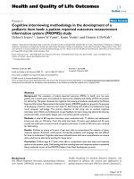
Control system architecture
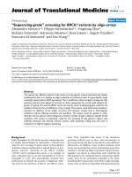
The conceptual scheme of the implemented control is
depicted in Fig. 1. It is a hierarchical structure, in which
the overall control task is shared between the user, a
hig h-level controller and a low-level embedded control-
ler. The u ser issues commands for hand opening and
closing via a simple EMG interface and also controls the
orientation of the hand during grasping and manipula-
tion. The high-level controller comprises: 1) the CVS
estimating object properties (size, shape) and automati-
cally selecting grasp type and aperture size appropriate
for grasping the object; and 2) a hand controller trans-
lating the selected grasp into a set of desired finger posi-
tions (for hand p reshaping) and forces (fo r hand
grasping) that are sent to a low-level controller. The
low-level contro ller embedded into the CyberHand pro-
totype implements closed-loop position and force con-
trol during hand preshaping and grasping, respectively.
The novel contri bution of this study is the development
of the high-level controller and the integration of t he
aforementioned elements into a unified control
framework.
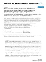
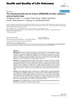
Experimental setup
The experimental setup consisted of the following com-
ponents (see Fig. 2): 1) the prosthetic hand mounted
onto an orthopaedic splint, 2) the CVS, 3) a two-chan-
nel EMG system, and 4) a standard PC (dual-core Pen-
tium 2 GHz) equipped with a DAQ card ( NI-DAQ
6062E, National Instruments, USA). The control was
run within an application developed in LabView 2009.
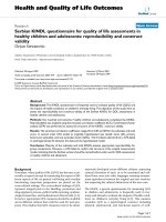
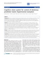
As can be seen from Figs. 2 and 3, the hand was rigidly
fixed for the orthopaedic splint (no wrist joint) and the
splint was attached to the subject's forearm by using
straps, in such a w ay that the artificial hand was just
below the subject's hand and oriented in the same man-
ner (i.e., the palm of the artificial hand was parallel to
the volar side of the subject's forearm). The subject
could rotate the artificial hand by using pronation/
supination.
Prosthetic hand
The stand-alone version of the CyberHand prototype
[44], already employed in many research scenarios
[25,45,46], was used to emulateaprosthetichand.It
consists of four under-actuated anthropomorphic fingers
and a thumb based on Hirose's soft finger mechanism
[47] and actuated by six DC motors. Five of them,
located re motely, control finger flexion/extension. One
motor, housed inside the palm, drives the thumb abduc-
tion/adduction. The hand is comparable in size to the
adult human hand, and the remote actuators are
assembled in an experimental platform that mimics the
shape of the human forearm. The remote actuators act
on their respective fingers using tendons and a Bowden
cable transmission. Active flexion is achieved as follows:
when a tendon is pulled, the phalanxes flex synchro-
nously, replicating the idle motion (i.e., free space
motion) of a human finger [48]. As a result of this
mechanism, the shape of the hand adapts to the shape
of an objec t automatically, providing multiple contact
points and a stable grasp. Therefore, the final geometri-
cal configuration of the hand is dictated by external
constraints imposed by the shape of the grasped object.
When a tendon is released, torsion springs located
within the joints extend the fingers, thereby providing
hand opening and releasing of the object.
The hand i nclu des encoders integrated in the mo tor
units (position sensors) and force sensors in series with
the tendons (for the assessment of the grasp force).
The controller embedded in the hand (low-level con-
troller i n Fig. 1) is an 8-bit, microcontroller-based archi-
tecture (Microchip Inc. microcontrollers); it is itself
organized in a hierarchical ma nner and consists of six
low-level motion controllers (LLMCs) and one high-level
Figure 1 Control system architecture. The Cognitive Vision
System (CVS) is integrated into a hierarchical control system for the
control of a dexterous prosthetic hand (emulated by the CyberHand
prototype). The user triggers the system and controls the
orientation of the hand. A high-level controller autonomously
selects the grasp type and size that are appropriate for the target
object. A low-level controller embedded into the hand provides a
stable interface for preshaping and grasping.
Došen et al. Journal of NeuroEngineering and Rehabilitation 2010, 7:42
/>Page 3 of 14
hand contr oller (HLHC). Each motor is di rectly actuated
and controlled by an LLMC that implements a propor-
tional-integral-derivative (PID) position control and force
control based on tendon tension. All LLMCs are directly
controlled by the HLHC , which regulates overall hand
operation and acts as an interface with the external
world. This interface comprises a set of commands that
canbesenttothehandfromahostPCviaastandard
RS232 serial link. It includes commands for reading t he
forces and positions, as well as for setting the finger posi-
tions in the range from 0 (fully open) to 100% (fully
flexed) and tendon forces in the range from 0 (no force)
to 100% (maximal force ~140 N).
Cognitive vision system (CVS)
The CVS is compo sed of a small-sized, low-cost web
camera (EXOO-M053, Science & Technology Develop-
ment Co. Ltd., China), an ultrasound distance sensor
(SRF04, Devantech Ltd., UK) and a laser pointer, housed
in a custom-made metal housing, mounted onto the
dorsal side of the hand using a pivot joint (see Fig. 3)
and communicating with a PC via a DAQ card and USB
port [43]. Two timer/counter modules on the DAQ card
were used to interface with the distance sensor: one to
generateatriggerpulsetostartthemeasurementand
the other to read the pulse-width-modulated (PWM)
sensor output. The web camera was connected directly
to a USB port of the PC, whereas the laser pointer was
simply powered by using the power lines of the USB
interface. The laser pointer was used to point at the
object that was the target for grasping, the web camera
provided the image of the object and the distance sensor
measured the distance to the target.
EMG system
Bipolar EMG was recorded from the finger flexor (flexor
digitorum superficialis and profundus) and extensor
muscles (extensor digitorum communis) by using stan-
dard, disposable, self-adhesive Ag/AgCl electrodes (size
3 × 2 cm, Neuroline 720, AMBU, SE). The outputs of
the EMG amplifi ers were connected t o the analog input
channels of the DAQ card. Single-channel isolated EMG
amplifiers (EM002-01, Center for Sensory-Motor Inter-
action, DK) were used. The input channel (CMRR >100
dB, input impedance >100 MΩ,gain≤10000) was
Figure 2 The implementation of the control system architecture. The ha rdware comprises: 1) the cognitive vision system (CVS), 2) a two-
channel EMG system, and 3) a PC with a data acquisition card. The PC runs a control application implementing a finite state machine that
triggers the following modules (gray boxes): the myoelectric control module, the CVS algorithm and the hand control module. The myoelectric
module acquires and processes the EMG, generating a two-bit code signalling the activity of the flexor and extensor muscles. This code is the
input for the state machine. The CVS algorithm estimates the size of the target object and uses a set of simple IF-THEN rules to select the grasp
type and aperture size appropriate to grasp the object. The hand control module implements the selected grasp parameters by sending the
commands to the embedded hand controller (HLHC) via an RS232 link.
Figure 3 Experimental platform. T he platform consi sts of: 1) the
CyberHand attached onto an orthopaedic splint, 2) the cognitive
vision system (CVS) mounted onto the dorsal side of the hand via a
pivot joint, and 3) the EMG electrodes for myoelectric control.
Došen et al. Journal of NeuroEngineering and Rehabilitation 2010, 7:42
/>Page 4 of 14
equipped with an analo gue secon d-order band-pass But-
terworth filter with the cut-off frequencies set at 5 and
500 Hz. The amplifiers were custom made at the Centre
for Sensory-Motor Interaction and used previously in a
number of motor control studies.
Control algorithm
The control algorithm integrates the following tasks: 1)
acquires input information: image and distance from the
CVS, and EMG signals from the amplifiers, 2) proces ses
the data, 3) generates hand control co mmands, and 4)
sends them to the hand. The control application imple-
ments a finite state machine in which transitions
between the main s tates (hand open and close) are trig-
gered by the user's EMG. The processing part, i.e., the
core of the application, comprises three distinct mod-
ules: the CVS algorithm, the myoelectric control and the
hand control modules (see Fig. 2).
The CVS algorithm processes the image and distance
information. In the first stage, computer vision methods
[43] are used to analyze the image in order to locate the
target object and to estimate its size, i.e., the lengths of
its short and long axes. The size is estimated using the
distance to the object (as measured by the distance sen-
sor), the length of the object axes in pixels, and the
focal length of the camera [43]. When the user triggers
the operation of the CVS (as explained later) , ten conse-
cutive measurements are performed. The final size esti-
mate is obtained as the median of these ten estimates.
The median is used in order to obtain more robust esti-
mation, since it is less affected by potential outliers
compared to the mean value.
The estimated object size is input for the cognitive
part of the algorithm that is implemented as a set of IF-
THEN rules. These rules compare the estimated size
against fixed thresholds (IF) and based on the results of
the comparisons, an appropriate grasp type and aperture
size is selected (THEN). The rules are constructed so
that four different grasp types can be chosen: palmar,
lateral, 3-digit and 2-digit (pinch) grasps. Furthermore,
palmar and lateral grasps are available in three different
aperture sizes (small, medium,andlarge) while the 3-
digit grasp has two available sizes (small and medium).
Therefore, there are nine possible grasp modalities in
total (see Table 1). The main principle in designing the
rules was to match the size of an object with a corre-
sponding functional grasp; large objects trigger the
selection of palmar or la teral grasps, whereas the 3-
digit and 2-digit grasps are used for small and very
small objects, respectively. If a large object is also wide
enough, a palmar grasp is chosen; otherwise, for thin
objects, a lateral grasp is used. The qualitative terms of
"small", "large", "wide" and "thin" are quantified using
numerical t hresholds, and the thresholds are expressed
in the percents of the hand size and the size of the max-
imal aperture when the artificial hand is preshaped
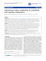
according to a given grasp type. As an example, Fig. 4
shows the rules used for the palmar grasp. Rules for the
other grasps are very similar (see t he additional file 1).
Importantly, different grasps are mutually exclusi ve, i.e.,
only one output can be generated by the CVS algorithm
for the given input.
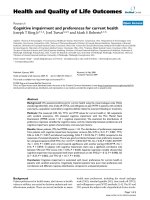
To demonstrate the operation of the CVS, we show in
Fig. 5 the representative outputs of t he CVS algorithm
obtained during the experiments describe d later in the
text. Pictures shown in Fig. 5(a)-(d) were generated
when the CVS aimed at different target objects used in
this study. Each image shows the detected object, the
measured distance (D), the estimated lengths of the
short (S) and long (L)objectaxes,andtheresulting
grasp type and size selected. For example, the object in
Table 1 Grasp types and sizes
Type of opposition Grasp type and aperture
size
Grasp
ID
Palm opposition
All palmar surfaces of the fingers and the palm are involved and the thumb is in opposition to other fingers
(as in grasping a bottle).
Palmar Large PL
Palmar Medium PM
Palmar Small PS
Side opposition
The thumb opposes the radial aspect of the index finger (as in grasping a key). Lateral Large LL
Lateral Medium LM
Lateral Small LS
Pad opposition
The opposition is formed between the fingertips of the thumb and the fingers (as in lifting a pin from a flat
surface).
3-digit Medium (index,
middle finger and thumb)
TM
3-digit Small TS
2-digit (index finger and
thumb)
B
Došen et al. Journal of NeuroEngineering and Rehabilitation 2010, 7:42
/>Page 5 of 14
Fig. 5(a) is long and thin, and the estimated grasp type
was therefore lateral. The CVS selected the same grasp
type for the object in Fig. 5(b), but since this time the
object was wider, the estimated aperture size was large.
Fig. 5(c) shows a small object for which the selected
grasp was 3-digit small and for the smallest object in
Fig. 5(d), the estimation was 2-digit grasp.
The prehension control commands generated by the
CVS algorithm are inputs for the hand control module.
ThetaskofthismoduleistosendtheproperHLHC
commands to the hand in order to preshape or close
the hand according to the output of the CVS. A lookup
table with the preshaping positions and tendon force
values (for stable grasps) that should be assumed by
each finger in each grasp was built. Values were chosen
based on Cutkosky's grasp taxonomy [39], i.e., the forces
were set according to the expected power demands in
different grasps (e.g., higher forces for palmar than for
2-digit grasp, higher forces for larger aperture sizes,
etc.).
The myoelectric control module simply thresholds the
EMG inputs in the following manner: raw EMG signals
are sampled at 2 kHz, and the mean absolute value
(MAV) is calculated over 100-ms overlapping time win-
dows. The MAVs of both channels are then thresholded
Figure 4 A decision t ree depicting the IF-THEN rules for the
selection of the grasp type and size. The inputs for the rules are
the estimated lengths of the object's short (S) and long (L) axes. The
lengths are compared against fixed thresholds (T) by following
decision nodes (diamond shapes) of the tree until one of the leaf
nodes (rounded rectangles) is reached. The thresholds are defined
relative to the hand size and the size of the maximal aperture when
the hand is preshaped according to a given grasp type. For
example, T
LARGE
= 90% PW, T
THIN
= 70% MLA, T
WIDE
= 50% MPA, and
T
VERYWIDE
= 65% MPA, where PW is the width of the palm (from
lateral to medial side), while MPA and MLA are the maximal aperture
sizes for the palmar and lateral grasps, respectively. For the full set
of rules see the additional file 1.
Figure 5 The representative outputs of the cognitive vision algorithm. The images depict the detected target object (see Table 2),
measured distance (D), estimated lengths of its short (S) and long (L) axes and estimated grasp type and aperture size. The actual object sizes
are given above the images. The estimated object axes are also shown graphically (superimposed gray lines). The bright spot is the reflection of
the laser beam. The figure demonstrates that the cognitive vision system estimates the grasp types and sizes that are appropriate for the size of
the target object. (Notations: Bidigit ~2-digit grasp, Tridigit ~3-digit grasp)
Došen et al. Journal of NeuroEngineering and Rehabilitation 2010, 7:42
/>Page 6 of 14
using individuall y adjustable levels, and a two-bit binary
code (first bit referring to flexor muscles and seco nd to
extensors) is generated. The binary code is input for the
application's state machine (see Fig. 6) implementing the
following steps:
1) The starting, idle state is where the robotic hand
is in a neutral posture (i.e., all fingers 60% flexed).
2) When the subject decides to grasp an object, he/
she needs to point with the laser beam toward the
object and activate his/her finger extensor muscles.
The recognized EMG activity that is larger than the
preset threshold starts the CVS algorithm for the
estimation of the pointed object size and selection of
the appropriate grasp type and aperture size.
3) Once the size and grasp type are selected, the
hand control module commands finger extension,
thereby providing preshaping.
4) The subject then grasps the object by positioning
the hand around the object and commanding its clo-
sure by activating his/her finger flexors. The artificial
hand grasps the object by using force control to flex
the involved fingers.
5) The obje ct is held until the subject contracts his/
herfingerextensormuscles,therebytriggeringthe
opening of the hand and releasing of the object.
6) The final phase is the retur n to the idle state
(after a three-second delay).
Experimental protocol: "reach, pick up and place" trials
The working principle of the system was tested in experi-
mental trials in which subjects operated the artificial
hand in the "reach, pick up and place" tasks. 13 able-
bodied subjects participated in the experiments (29 ±
4.5 years of age). All volunteer subjects signed the
informed consent approved by the local ethics committee.
Figure 6 Finite state machine for the control of the artificial hand. The control i s realized as an integration of the cognitive vision system
(CVS) with myoelectric control. The two channels of electromyography (EMG) recorded from finger extensors (Ext EMG) and flexors (Flex EMG)
drive the system through the states by providing a two-bit binary code (in brackets); the first bit signals the activity of the flexors and the
second is for the extensors, while X means "don't care." The user aims the system toward a target object and triggers the hand opening. The
CVS estimates the grasp type and size. The user reaches for the object, commands the hand to close, manipulates the object and finally
commands the hand to open and release the object. Notations: rounded rectangles - states; full black circle - entry state; arrows - state
transitions with events.
Došen et al. Journal of NeuroEngineering and Rehabilitation 2010, 7:42
/>Page 7 of 14
The subjects were comfortably seated on an adjustable
chair in front of a desk where a workspace was orga-
nized (see Fig. 7). The workspace comprised a plane
background wit h five positions marked: the initial
(rest) position for the hand (labelled IP), two positions
(A1 and A2) where the objects to be picked up were
placed, and two positions (B1 and B2) to which the
objects had to be transported; B1 and B2 were used as
the final positions if the object was initially at A1 or
A2, respectively. The positions A1 and A2 were 30 cm
and 50 cm away from the initial position, respectively.
18 objects listed in Table 2 were selected as targets;
the objects were chosen in order to have two samples
for each of the grasp types given in Table 1. The task
was to reach, grasp, transport and release the target
object by operating the artificial hand as explained in
the previous section. The subject was instructed to place
the hand on the initial position so that the ulnar side of
the hand rested on the table. Upon receiving an auditory
cue, he/she had to drive the system through all of the
states of the st ate machine by usin g myoelectric control,
as shown in Fig. 6. During aiming, the subject was told
to orient the hand so that the palm was facing down,
parallel to the surface of the table. This orientation was
selected to ensure that the CVS operated in identical
conditions during the experiment, and also because dur-
ing the preliminary tests, the subjects reported that this
orientation was the easiest for aiming. After the CVS
finished processing and the hand started preshaping, the
subjects were free to move the system in any way
desired. There were two blocks of 18 trials for each sub-
ject. In the first block, the target objects were placed at
the location A1 (i.e., the sequence was IP-A1-B1), while
in the second block, the location was A2 (i.e., the
sequence was therefore IP-A2-B2). In both blocks, the
targe t objects were selected in a random order. In order
to minimize muscle fatiguing due to the perceived
weight of the prosthesis (about 300 grams for the pros-
thesis and about 100 grams for the CVS on a longer
lever-arm, compared to the natural hand), there was a
five-minute resting period between the two blocks.
Two of the subjects participated in a longer experi-
ment comprising fo ur extra blocks (six in total, alternat-
ing between A1 and A2) of 18 trials separated by five-
minute breaks in order to better analyze improvements
in performance due to learning.
At the beginning of the experiment, the amplifier
gains and EMG thresholds were set to meet individual
abilities of each subject. T he subjects practiced the use
of the system for about ten minutes. Attention during
practicing was primarily paid to the proper pointing of
the laser beam towards the object and to generating the
appropriate muscle contractions of the finger extensors
and flexors above the preset thresholds.
The following outcome measures have been used to
evaluate the performance: 1) estimation accuracy: the
estimation was considered s uccessful if the grasp type
and size were estimated accordin g to the classification
given in Table 2; 2) task accomplishment: the task was
considered accomplished if the object was correctly
picked up, transported and placed at the target location
(as in [25] ); and 3) the tot al time sp ent to acc omplish
the task. In the analysis, we considered that the task
accomplishment and successful estimation are not
directly related. Namely, the task could be accomplished
even though a wrong grasp was used (e .g., lateral gr asp
to pick up a bottle); on the other hand, the subject
could fail to do the task despite the fact that the grasp
was successfully estimated (e.g., the object slipped).
Statistical differences among experimental results were
evaluated using the Wilcoxon signed rank test for com-
paring two groups with paired data (i.e., repeated mea-
surements) and the Friedman test for the simultaneous
comparison of more than two groups with paired data.
If the Friedman test suggested that there was a differ-
ence, group s were compared pairwise using the Bonfer-
roni adjustment. Non-parametric tests were used since
the collected data did not pass the tests for normality
(e.g., Lilliefors test). Due tothesamereason,median
and inter-quartile ranges were selected as the summary
statistics for the data. The groups for the statistical
Figure 7 Experimental workspace. The notations are: IP - initia l
position for the hand; A1, A2 - initial positions for the object to be
grasped; B1, B2 - target locations for the object placed at A1 and
A2, respectively. The task for the subject was to reach for an object,
grasp it, transport it to the target location and release it. Two
sequences were used depending on the initial position of the
object: IP-A1-B1 and IP-A2-B2.
Došen et al. Journal of NeuroEngineering and Rehabilitation 2010, 7:42
/>Page 8 of 14
analysis were formed based on t he blocks of trials. For
example, the results achieved in the first block (group 1)
were compared with the results obtained in the second
block (group 2). The data from two different groups
were paired based on the same target object and/or sub-
ject . For example, the time spent to gras p and transport
a small cup in the first block ( a result from group 1)
was paired with the time spent to grasp and transport
thesameobjectinthesecondblock(aresultfrom
group 2). A level of p < 0.05 was selected as the thresh-
old for the statistical significance. The statistical analysis
was performed using MatLab 2009b (The MathWorks,
Natick, MA, USA) scripts.
Results
13 subjects performed a total of 612 grasp trials; among
these, 11 subjects performed 2 blocks of 18 trials , and 2
subjects performed 6 blocks of 18 trials. Overall, the
CVS correctly estimated both grasp type and grasp size
in 84% of the cases. In a n additional 6% of the cases,
the estimation was wrong but the task was st ill success-
fully accomplished. Two different errors were observed
here. In half of the cases, the grasp type was correctly
estimated but the grasp size was actually larger than the
correct one. For example, the CVS estimated palmar
large foranobjectthatwassupposedtobeclassifiedas
a palmar medium grasp. Obviously, this type of error
could not jeopardize the task accomplishment. In the
other half of the cases, the e stimated grasp type was
actually wrong, but it was still similar enough to accom-
plish the task. For instan ce, instead of using the 2-digit
grasp for a very small object, the CVS estimated 3-digit
small. Therefore, from the functional point of view, the
estimation was successful in about 90% of the trials.
No statistical difference between the estimation
accuracies obtained for the two diff erent distances (i.e.,
IP-A1 and IP-A2) was found. Importantly, if the number
of choices in the rule-based classification was decreased,
the success rate improved. For example, if the output
was limited to just two sizes for the lateral and palmar
grasps and a single size for the 3-digit grasp (i.e., mer-
ging medium and small grasps), the classification was
successful in 89% of the cases. Finally, if considering the
grasp type only (regardless of the grasp size), the success
rate was 93%. The results achieved in this study are
summarized in Figs. 8 and 9.
From the point of view of successful task accomplish-
ment, 5 out of 13 subje cts showed an improvement
between the second and first blocks of trials. The sub-
ject that showed the best improvement failed five times
in the first block and just once in the second block of
trial s. Considering the whole group, the total number of
unsuccessful tasks decreased from 27 in the first block
to 20 in the second. Two subjects who performed six
blocks had no failures in the last block of trials. For the
above analysis, only the trials that were unsuccessful
despitethefactthatthegrasptypeandsizewere
Table 2 Target objects
Grasp
ID
Object Size of the back plane projection
S × L [cm]
Mass
[g]
PL Cylinder 10 × 18 650
PL Cylinder 11 × 17 600
PM Big cup 8 × 9 280
PM Big bottle 8 × 25 550
PS Spray Can 6 × 12 220
PS Small bottle 6 × 22 480
B Rubber 1 1 × 1.5 10
B Rubber 2 1.5 × 3 15
TS Lego
element
3 × 5.5 10
TS Very small
bottle
3×7 30
TM Tennis Ball 6 60
TM Light bulb
box
5×5 70
LS Felt-tip pen 1 1 × 11.5 20
LS Pen 1 × 13 25
LM Felt-tip pen 2 2.5 × 11.5 30
LM Pen box 1 2.5 × 16 40
LL Pen box 2 4 × 16 35
LL Plastic box 3.5 × 13 80
Notations: S, L - short and long axes, respectively.
Figure 8 Overall estimation accuracy for the grasp type and
size. Both grasp type and size were correctly estimated in 84% of
the cases. In 3% of the cases, the type was correct and the size was
larger than the correct one. We had the same number of cases (3%)
in which the grasp was wrong but still similar enough for the
subject to accomplish the task. Therefore, from the functional point
of view, the classification was successful in 90% of the cases (all
gray slices).
Došen et al. Journal of NeuroEngineering and Rehabilitation 2010, 7:42
/>Page 9 of 14
correctly estimated were taken into account (otherwise,
the responsibility for the failure was attributed to the
CVS).
The analysis on a subject by subject basis showed that
in10outof13subjects,themediantimespentto
accomplish the task decreased in the second block of
trials. Maximal registered improvement was 4.45
seconds. In eight of these ten subjects , the change was
statistically significant. When regression lines were fitted
through the data for each subject organized across the
trials, the line slope was negative in 11 subjects, suggest-
ing a trend for the decrease in time during the course of
the experiment. When the first and second blocks were
comp ared by considering the whole group (all subjects),
the median decreased from 17 to 14.9 seconds, and this
change was statistically significant.
Fig. 10 clearly shows the improvement in performance
throughout the experiment for one of the subjects that
took part in the longer evaluation (i.e., 6 blocks × 18
trials); results for the s econd subject were comparable
but for a better readability of the graph they are not
included. The plot in Fig. 10(a) presents the time spent
to accomplish the task versus the trial number. A cubic
polynomial was fitted to the data to show the trend:
time decreased and this d ecrease was slowing down. If
the times are compared between the consecutive blocks,
paired by the targe t object (Fig. 10[b]), then the median
time in the first block was 19.4 seconds and it dropped
to 10.3 seconds in the last block.
Discussion
The goal of this study is to present and assess a novel
concept for the control of grasping in transradial pros-
theses. The core of the presented architecture is the
cognitive v ision system (CVS) that uses artificial vision
and a rule-based decision making to analyze the target
object and to generate proper commands for the control
of prehension. The tests showed that the autonomous
artificial controller w as successfully integrated with the
biological control of able-bodied users. The CVS was
combinedwithasimpleEMGinterfaceresultingina
fully functional prototype of an artificial hand operated
by means of a shared (cooperative) control. The user
was responsib le for aiming, triggering, and orienting the
hand while the automatic control implemented the
selection of the grasp type and size, hand preshaping
(position control) and grasping (force control). The pro-
totype was successfully tested in healthy sub jects that
used it to grasp, transport and release a set of common
objects. The current results ( i.e., short training, suc cess
rates, and overall user impression) imply that the pro-
posed concept might be successfully translated to the
control of a dexterous prosthetic han d operated by
amputees.
The controller designed in this study is capable of
making high-level decisions autonomously. As a result,
the communication link between the user and the sys-
tem is very simple; the user issues just the basic com-
mands (e.g., trigg ering grasp and release), and the
controller implements the rest. Importantly, since the
CVS is a self-contained component that uses a novel
Figure 9 Classification accuracy for different number of
possible outputs. If the number of possible outputs (i.e., hand
preshape commands) that the IF-THEN rules can generate is
decreased, the success rate improves. Groups: 1 - all grasp types
and sizes, 2 - two grasp sizes for the lateral and palmar grasps and
one grasp size for the 3-digit and 2-digit grasps; 3 - only grasp
types (i.e., one grasp size for all grasp types).
Figure 10 Improvements in performance due to learning.The
figure shows the results (time spent to accomplish the task)
organized as a) individual trials and b) blocks of trails. The vertical
axis is the time needed to accomplish the task. In plot a), the trend
obtained by fitting a cubic polynomial through the experimental
results (black dots) is shown by a continuous line, and the
boundaries between the blocks of trials are depicted by the dashed
vertical lines. In plot b), the horizontal lines are the medians, boxes
show inter-quartile ranges and whiskers are minimal and maximal
values. Statistically significant difference is denoted by a star. The
time needed to successfully accomplish the task decreases steadily
during the experiment.
Došen et al. Journal of NeuroEngineering and Rehabilitation 2010, 7:42
/>Page 10 of 14
type of feedback (i.e., artificia l vision and ultr asound), it
can be combined/integrated with the other aforemen-
tioned control schemes described in the literature (e.g.,
[16,32,49,50]).
Theuseofthesystemisintuitive.Thesubjectacti-
vates hand pre shaping by contracting his/he r finger
extensors and then closes the hand by activating the fin-
ger flexors, which follows the healthy-like grasping mus-
cle activation. The automatic control eases the burden
from the user and, as a result, the user can concentrate
on what he/she does and not on how he/she should do
it. The other quality is that the intuitive control allowed
the operation with virtually no prior training. In the pre-
sent experiment, less than 15 minutes of practicing were
enough for the subjects to start using the system suc-
cessfully. During that time, the subjects learned to gen-
erate proper EMG signals, to aim at the target object
using a laser beam, and to orient the hand for grasping
and during manipulation. However, the cu rrent test was
conducted in healthy subjects. In transradial amputees,
who are the actual target population, setting up the
EMG interface and learning its use could take more
time depending on the state of the residual limb (i.e.,
severity of the damage). Nevertheless, it is still the sim-
plest form of the myoelectric control ( i.e., only two
channels, discrete control) that the subjects would have
to master. With respect to aiming, there should be no
significant difference betweentheabilityoftransradial
amputees with the healthy elbow and upper ar m, and
the healthy population.
The requirement to aim the laser at the target object
is a potentially counter intuitive step in the proposed
approach. As shown in Fig. 3, the CVS was mounted
above t he hand, which is not an ideal position because
the optical axes of the camera and the direction of the
ultrasound burst are not aligned with the axis of the
forearm. Therefore, the aiming with the laser had to be
used to ensure that, in the initial phase of the move-
ment, the user oriented the hand so that the target
object was actually picked up by the sensors. However,
the subjects in general had no d ifficulties in mastering
this step. The aiming lasted from 2 to 3 seconds in aver-
age, even for the small objects. Furthermore, as will be
explained later, the future goal is to miniaturize and
integrate the CVS into the hand itself. In that case, the
axes of the sensors would align with the axis of the fore-
arm and the aiming could become automatic (subcon-
scious), i.e., it could be an integral part of the approach
phase during which the hand aligns with the target
object in preparation for the grasp.
The outputs of the CVS are the estimated grasp type
and aperture size appropriate for grasping the detected
targ et object. Both outputs are essential for the success-
ful grasping using an anthropomorphic art ificial hand. If
the grasp type is not adequate, it could be difficult to
form a stable grip, as documented well in the studies on
robotic grasping [36,39]. As demonstrated for the
human [51] and robotic grasp planning [25,52], assum-
ing a proper aperture plays a key ro le, i.e., f orming an
aperture with the size that is adapted to that of the
object allows for a more accurate reaching and position-
ing of the hand and therefore leads to a better prepara-
tion for the following enclosing phase. This reasonably
increases the chances of forming a stable grip.
The CVS was cap able of generati ng nine different
commands (i.e., combinations of grasp types and sizes)
with a success rate of 84%. If the number of possible
commands from the CVS was reduced, the success rate
increased (up to 93%); thus, th is control principle allows
selection of the suitable trade-off between desired
sophistication and robustness. In general, it is hard to
define precisely and objectively what would be the
acceptable performance for the eventual practical appli-
cation (e.g., see the discussion of the "hot coffee pro-
blem" in [21]). Nevertheless, to reach a higher level of
robustness , the current objective for the CVS classifica-
tion is to improve the performance even further so that
the error rates are reduced to below 5%. This can be
done by improving the image processing and/or distance
estimation as described later in the text.
The cognitive vision algorithm tested in this study was
operating on the PC in the LabView environment. The
processing of an image and the size estimation lasted an
average of 0.3 se conds. As explained before, ten of these
snapshots were taken and processed before the com-
mand could be sent to the hand. Overall, the period
between the moment when the user issued a command
(i.e., contracted his muscles) and the start of hand pre-
shaping was too long: about 4 seconds (on average).
Farrell and Weir [53] defined the notion of optimal con-
troller-induced delay as the maximum amount of time
that can be used by the controller for data collection
and analysis without affecting prosthesis user perfor-
mance. They also noted that there is no general agree-
ment in the existing literature about the acceptable
delays; the estimates in different studies range from as
low as 50 to up to 400 milliseconds. One reason for this
disagreement could be the fa ct that the acceptable delay
likely depends on the specific control method used (e.g.,
proportional, discrete control) as well as on the mechan-
ical characteristics of the prosthesis (e.g., speed of open-
ing and closing). For the controller presented in this
manuscript, the current goal is to decrease the delay so
that it falls somewhere within the range of acceptable
delaysgivenintheliterature (~few hundred millise-
conds). This can be done by im plementing the control-
ler within an embedded platform and by optimizing the
processing.
Došen et al. Journal of NeuroEngineering and Rehabilitation 2010, 7:42
/>Page 11 of 14
In the present study, unsuccessful grasps were caused
by the three main reasons: 1) subjects made mistakes
and failed t rials while learning how to operate the sys-
tem (in the initial trials, subjects wrongl y positioned the
hand around small objects; hence, the fingers missed the
object while closing); 2) the CVS generated wrong com-
mands due to wrong estimation of the object size; and
3) EMG triggering failed, especially in the initial trials
while the subjects were still learning how to generate
the commands. The wrong estimation of the object size
was caused by the following: a) image segmentati on and
b) distance errors. We discuss these reasons below:
a) The segmentation is, in computer vision, the task of
separating the object from the background; it is a crucial
step in the algorith m since it allows the ident ification of
the target object. During the experiments, the segmenta-
tion in some cases failed, "mistaking" a part of the back-
ground as a part of the object or vice versa. This led to
a wrong estimation of the object axis lengths, that is,
incorrect grasp type and/or size selection. Imperfect seg-
mentation is a common problem in computer vision
[54,55], and this limitation has already been identified in
our earlier study [43]. As a result, in the present study,
we improved the recognition by implementing an edge-
based segmentation in the RGB colour space [56].
b) The wrong estima tions were also caused by a false
reading from the distance sensor: it sometimes regis-
tered a reflection from an object that was not the target
(e.g., an edge of the table) or it missed the target object
completely. The latter was the case when the target
object was small. This error could be minimized by test-
ing sensors equipped with different models of ultra-
sound transceivers [57] in order to find an optimal
diameter of the cone of the emitted ultrasound burst (i.
e., having a more or less focused beam).
Although the main goal of this study was to evaluate
the performance of the control algorithm, we were also
interested in assessing how easy it was to operate the
system and if the subjects would improve their perfor-
mancebylearninghowtouseit.Resultsareencoura-
ging, showing that the s ubjects were able to op erate the
system well just after a sh ort period o f practice (less
than 15 minutes): all subjects failed less than five times
(out of 18) in the first block of trials. Furthermore, in
the second block, the subjects decreased the time
needed to accomplish the task without actually sacrifi-
cing their performance. For example, the subjects
learned that they could start reaching for the target
object before the hand was fully preshaped into the
selected grasp. Importantly, this is how the normal
human grasp naturally develops; the transport and pre-
shape components evolve in parallel.
It is important to emphasize that the goal of this work
was to test the feasibility of the overall approach and not
to test, fine tune and perfect all of its component parts.
For example, the surface of the table and the wall behind
the objects were in the plane colours during the experi-
ments. Since the segmentation is based on edge detec-
tion, identifying an object in an image with a strongly
textured background would be a much more challenging
task. Due to similar re asons, the current algorithm would
not perform well in cluttered environments, i.e., when
there are many obje cts close and behind each other.
Importantly, these issues are the focus of research in the
computer vision community, and it is therefo re to be
expected that new solutions will soon emerge. Since the
system proposed here is modular, the novel algorithms
can be incorporated easily as soon as they appear.
In terms of aesthetics, again, the system shown in Fig. 3
should be regarded only as a first prototype. The CVS is
presently mounted on the hand as a separate component;
the sensor elements (e.g., lenses and image sensor, ultra-
sound transmitter and receiver) and their supporting
electronics are housed in two metal boxes (see Fig. 3).
However, the future goal is to integrate the CVS into a
prosthetic hand. The sensor electronics will be merged
with the electroni cs of the hand, and both will reside
within the palm. The best positions for mounting the
lenses and ultrasound transceivers (miniaturized ver-
sions) will be identified by testing. One possibility would
be to place the compone nts in the palm between the
metacarpophalangeal joints. In the neutral hand posture,
the fingers are somewhat flexed, and this would ensure a
free line of sight. The cosmetic covering should have
smal l openings for the sens ors and the camera. Since the
CVS implements a robust estimation rather than a fine
and sensitive analysis, the new components will add a
marginal load to the standard procedures for the hand
maintenance (i.e., the lenses will have to be kept relatively
clean). For one example of a camera that is actually a part
of the robotic hand, see [58].
Future work will be focused mainly on developing a
more robust computer vision part of the algorithm. For
example, vector-based approaches for edge detection
[56] or region growing methods [54] for object segmen-
tation are possible directions for future research. How-
ever, these methods are significantly more demanding in
terms of processin g, and fast algorithms convenient for
real-time implementation have yet to be developed.
Regarding the hardware, the next step is to realize it as
an embedded computer platform, such as the one pre-
sented in [59], and integrate it into a func tional transra-
dial prosthesis [3] in order to assess the usability of t he
approach in amputees.
Conclusions
The original contribution of this research is a novel con-
troller that uses vision and reasoning borrowed from
Došen et al. Journal of NeuroEngineering and Rehabilitation 2010, 7:42
/>Page 12 of 14
biological control to implement high-level analysis (i.e.,
determining object properties) and autonomous deci-
sion-making (i.e., selecting appropriate grasp type and
size). Importantly, the controller is designed to be con-
venient for real-time application: the image processing
pipeline is minimal and the rea soning module comprises
a set of simple IF-THEN rules. The automatic control
eases the burden from the user; he/she is responsible for
issuing just the basic commands of "open" and "close"
via a simple two-channel EMG interface. As a result, the
user can concentrate on what he/she does, not on how
he/she should do it. The tests showed that the perfor-
man ce of the s yste m was satisfactory and that the users
could successfully operate the system with minimal
prior training. Having an intelligent controller that oper-
ates autonomously while being integrated within the
volitional control of the user, and thereby complement-
ing the user in controlling the system, is essential for
the implementation of complex control scenarios
exploiting the full flexibility of the modern dexterous
prosthetic hands.
Additional material
Additional file 1: IF-THEN rules. The complete set of rules for selecting
the grasp type and aperture size.
Acknowledgements
This work is part of the research funded through the EC FP6 project "The
Smart Bio-adaptive Hand Prosthesis (SmartHand)", Contract No: NMP4-CT-
2006-0033423.
The activities were partly supported by the Ministry of Science and
Technology of Serbia, Belgrade. We would like to thank our volunteer
subjects for participation in the project.
Author details
1
Center for Sensory-Motor Interaction, Department for Health Science and
Technology, Aalborg University, 9220, Aalborg, Denmark.
2
Advanced
Robotics Technology and Systems Laboratory, Scuola Superiore Sant'Anna,
56025, Pontedera, Italy.
3
Faculty of Electrical Engineering, University of
Belgrade, 11000, Belgrade, Serbia.
Authors' contributions
SD and CC contributed to all the stages of this research (i.e., planning,
implementing, conducting experiments and writing). DBP conceived the
concept of the novel control method, and participated in designing the
control system, in planning the experiments, as well as in writing. MK
contributed in the development of the image processing part of the control
algorithm. MC and MCC developed the hand and took part in writing. All
authors read and approved the final manuscript.
Competing interests
CC and MC hold Prensilia Srl, the company that manufactures robotic hands
as the one used in this work, under the license to Scuola Superiore
Sant'Anna.
Received: 11 February 2010 Accepted: 23 August 2010
Published: 23 August 2010
References
1. Motion control hand. [ />2. Upper extremity prosthetics. [ />ob_us_en/hs.xsl/5057.html].
3. Cipriani C, Controzzi M, Carrozza MC: Objectives, criteria and methods for
the design of the SmartHand transradial prosthesis. Robotica 2009.
4. Cipriani C, Controzzi M, Carrozza MC: Progress towards the development
of the SmartHand transradial prosthesis. Proc Int Conf Rehabil Robot,
ICORR, Jun 23-26, 2009; Kyoto, Japan 2009, 682-687.
5. Huang H, Jiang L, Liu Y, Hou L, Cai H, Liu H: The Mechanical Design and
Experiments of HIT/DLR Prosthetic Hand. Proc IEEE Int Conf Robot Biomim,
ROBIO 2006, 896-901.
6. Gaiser IN, Pylatiuk C, Schulz S, Kargov A, Oberle R, Werner T: The
FLUIDHAND III: A Multifunctional Prosthetic Hand. JPO J of Prosthet Orthot
2009, 21:91-96.
7. The i-LIMB hand. [ />8. RSL Steeper Bebionic. [ />9. Otto Bock R&D. [ />10. Cotton DPJ, Cranny A, Chappell PH, White NM, Beeby SP: Control
strategies for a multiple degree of freedom prosthetic hand. Meas
Control 2007, 40:24-27.
11. Craelius W: The Bionic Man: Restoring Mobility. Science 2002,
295:1018-1021.
12. Zecca M, Micera S, Carrozza MC, Dario P: Control of multifunctional
prosthetic hands by processing the electromyographic signal. Crit Rev
Biomed Eng 2002, 30:459-485.
13. Mainardi E, Davalli A: Controlling a prosthetic arm with a throat
microphone. Proc 29th Annu Int Conf EMBS 2007, 3035-3039.
14. Carrozza MC, Persichetti A, Laschi C, Vecchi F, Lazzarini R, Vacalebri P,
Dario P: A Wearable Biomechatronic Interface for Controlling Robots
with Voluntary Foot Movements. IEEE-ASME Trans Mechatron 2007, 12:1-11.
15. Curcie DJ, Flint JA, Craelius W: Biomimetic finger control by filtering of
distributed forelimb pressures. IEEE Trans Neural Syst Rehabil Eng 2001,
9:69-75.
16. Parker P, Englehart K, Hudgins B: Myoelectric signal processing for control
of powered limb prostheses. J Electromyog Kines 2006, 16:541-548.
17. Guanglin L, Schultz AE, Kuiken TA: Quantifying Pattern Recognition-Based
Myoelectric Control of Multifunctional Transradial Prostheses. IEEE Trans
Neural Syst Rehabil Eng 2010, 18:185-192.
18. Chan ADC, Englehart KB: Continuous myoelectric control for powered
prostheses using hidden Markov models. IEEE Trans Biomed Eng
2005,
52:121-124.
19. Huang Y, Englehart KB, Hudgins B, Chan ADC: A Gaussian mixture model
based classification scheme for myoelectric control of powered upper
limb prostheses. IEEE Trans Biomed Eng 2005, 52:1801-1811.
20. Almstrom C, Herberts P, Korner L: Experience with Swedish
multifunctional prosthetic hands controlled by pattern recognition of
multiple myoelectric signals. Int Orthop 1981, 5:15-21.
21. Ajiboye AB, Weir RF: A heuristic fuzzy logic approach to EMG pattern
recognition for multifunctional prosthesis control. IEEE Neural Syst Rehabil
Eng 2005, 13:280-291.
22. Nishikawa D, Yu W, Yokoi H, Kakazu Y: On-line learning method for EMG
prosthetic hand control. Electron Commun Jpn Part III Fundam Electron Sci
2001, 84:35-46.
23. Castellini C, Van Der Smagt P: Surface EMG in advanced hand prosthetics.
Biol Cybern 2009, 100:35-47.
24. Naidu DS, Chen CH, Perez A, Schoen MP: Control strategies for smart
prosthetic hand technology: An overview. Proc 30th Annu Int Conf EMBS,
Vancouver 2008, 4314-4317.
25. Cipriani C, Zaccone F, Micera S, Carrozza MC: On the shared control of an
EMG-controlled prosthetic hand: Analysis of user-prosthesis interaction.
IEEE Trans Robot 2008, 24:170-184.
26. Lake C, Miguelez JM: Comparative Analysis of Microprocessors in Upper
Limb Prosthetics. J Prosthet Orthot 2003, 15:48-63.
27. Otto Bock Catalogs - Myobock system. [ />rde/xchg/ob_us_en/hs.xsl/19733.html].
28. Kuiken TA, Li G, Lock BA, Lipschutz RD, Miller LA, Stubblefield KA,
Englehart KB: Targeted muscle reinnervation for real-time myoelectric
control of multifunction artificial arms. J Am Med Assoc 2009, 301:619-628.
Došen et al. Journal of NeuroEngineering and Rehabilitation 2010, 7:42
/>Page 13 of 14
29. Miller LA, Stubblefield KA, Lipschutz RD, Lock BA, Kuiken TA: Improved
myoelectric prosthesis control using targeted reinnervation surgery: A
case series. IEEE Trans Neural Syst Rehabil Eng 2008, 16:46-50.
30. Tomović R, Boni G: An adaptive artificial hand. IRE Trans Autom Contr
1962, AC-7:3-10.
31. Rakić M: An automatic hand prosthesis. Med Electron Biol Eng 1964,
2:47-55.
32. Nightingale JM: Microprocessor control of an artificial arm. J Microcomput
Appl 1985, 8:167-173.
33. Chappell PH, Nightingale JM, Kyberd PJ, Barkhordar M: Control of a single
degree of freedom artificial hand. J Biomed Eng 1987, 9:273-277.
34. Kyberd PJ, Evans M, Te Winkel S: An intelligent anthropomorphic hand,
with automatic grasp. Robotica 1998, 16:531-536.
35. Kyberd PJ, Chappell PH, Nightingale JM: Sensory control of a
multifunction hand prosthesis. Biosensors 1987, 3:347-357.
36. MacKenzie CL, Iberall T: The Grasping Hand Amsterdam: Elsevier B.V 2010.
37. Jeannerod M: Visuomotor channels: Their integration in goal-directed
prehension. Hum Mov Sci 1999, 18:201-218.
38. Jeannerod M, Arbib MA, Rizzolatti G, Sakata H: Grasping objects: the
cortical mechanisms of visuomotor transformation. Trends Neurosci 1995,
18:314-320.
39. Cutkosky MR: On grasp choice, grasp models, and the design of hands
for manufacturing tasks. IEEE Trans Rob Autom 1989, 5:269-279.
40. Iberall T: A Neural Network for Planning Hand Shapes in Human
Prehension. Amer Contr Conf 1988, 2288-2293.
41. Tomović R, Bekey G, Karplus W: A strategy for grasp synthesis with
multifingered robot hands. Proc IEEE Int Conf Robot Autom 1987, 83-89.
42. Iberall T, Beattie DJ, Sukhatme G, Bekey G: Control Philosophy for a
simulated prosthetic hand. Proc RESNA, Las Vegas 1993, 12-17.
43. Došen S, Popović DB: Transradial prosthesis: artificial vision for control of
prehension. Artif Organs 2010.
44. Carrozza MC, Cappiello G, Micera S, Edin BB, Beccai L, Cipriani C: Design of
a cybernetic hand for perception and action. Biol Cybern 2006,
95:629-644.
45. Panarese A, Edin BB, Vecchi F, Carrozza MC, Johansson RS: Humans can
integrate force feedback to toes in their sensorimotor control of a
robotic hand. IEEE Trans Neural Syst Rehabil Eng 2009, 17:560-567.
46. Cipriani C, Antfolk C, Balkenius C, Rosen B, Lundborg G, Carrozza MC,
Sebelius F: A novel concept for a prosthetic hand with a bidirectional
interface: a feasibility study. IEEE Trans Biomed Eng 2009, 56:2739-2743.
47. Hirose S: Connected differential mechanism and its applications. Proc Int
Conf Adv Robot, Tokyo, Japan 1985, 319-326.
48. Zollo L, Roccella S, Guglielmelli E, Carrozza MC, Dario P: Biomechatronic
design and control of an anthropomorphic artificial hand for prosthetic
and robotic applications. IEEE/ASME Trans Mechatron 2007, 12:418-429.
49. Light CM, Chappell PH, Hudgins B, Engelhart K: Intelligent multifunction
myoelectric control of hand prostheses. J Med Eng Technol 2002,
26:139-146.
50. Ahmad SA, Chappell PH: Artificial prehension and the detection of object
slip. Proc World Congr Med Phys Biomed Eng: Neuroeng, Neural Syst, Rehabil
Prosthet; Munich 2009, 231-234.
51. Santello M, Soechting JF: Gradual molding of the hand to object
contours. J Neurophysiol 1998, 79:1307-1320.
52. Ciocarlie MT, Allen PK: Hand posture subspaces for dexterous robotic
grasping. Int J Robot Res 2009, 28:851-867.
53. Farrell TR, Weir RF: The Optimal Controller Delay for Myoelectric
Prostheses. IEEE Neural Syst Rehabil Eng 2007, 15:111-118.
54. Palus H: Color image segmentation: selected techniques. In Color image
processing: methods and applications. Edited by: Lukac R, Plataniotis KN. CRC;
2007:103-128.
55. Russ JC: Segmentation and Thresholding. Image Processing Handbook
Boca Raton: CRC Press, 5 2007, 397-439.
56. Smolka B, Venetsanopoulos AN: Noise reduction and edge detection in
color images. In Color image processing: methods and applications. Edited
by: Lukac R, Plataniotis KN. CRC; 2007:75-100.
57. Robot sensors. [ />58. Milighetti G, Ritter M, Kuntze HB: Vision Controlled Grasping by Means of
an Intelligent Robot Hand. In Advances in Robotics Research: Theory,
Implementation, Application. Edited by: Kröger T, Wahl FM. Springer Berlin
Heidelberg; 2009:215-226.
59. CMUcam3 Open Source Programmable Embedded Color Vision
Platform.
[ />doi:10.1186/1743-0003-7-42
Cite this article as: Došen et al.: Cognitive vision system for control of
dexterous prosthetic hands: Experimental evaluation. Journal of
NeuroEngineering and Rehabilitation 2010 7:42.
Submit your next manuscript to BioMed Central
and take full advantage of:
• Convenient online submission
• Thorough peer review
• No space constraints or color figure charges
• Immediate publication on acceptance
• Inclusion in PubMed, CAS, Scopus and Google Scholar
• Research which is freely available for redistribution
Submit your manuscript at
www.biomedcentral.com/submit
Došen et al. Journal of NeuroEngineering and Rehabilitation 2010, 7:42
/>Page 14 of 14