Báo cáo hóa học: " Patient specific ankle-foot orthoses using rapid prototyping" pptx
Bạn đang xem bản rút gọn của tài liệu. Xem và tải ngay bản đầy đủ của tài liệu tại đây (986.58 KB, 11 trang )
RESEARCH Open Access
Patient specific ankle-foot orthoses using rapid
prototyping
Constantinos Mavroidis
1*
, Richard G Ranky
1
, Mark L Sivak
1
, Benjamin L Patritti
2
, Joseph DiPisa
1
, Alyssa Caddle
1
,
Kara Gilhooly
1
, Lauren Govoni
1
, Seth Sivak
1
, Michael Lancia
3
, Robert Drillio
4
, Paolo Bonato
2,5*
Abstract
Background: Prefabricated orthotic devices are currently designed to fit a range of patients and therefore they do
not provide individualized comfort and function. Custom-fit orthoses are superior to prefabricated orthotic devices
from both of the above-mentioned standpoints. However, creating a custom-fit orthos is is a laborious and time-
intensive manual process performed by skilled orthotists. Besides, adjustments made to both prefabricated and
custom-fit orthoses are carried out in a qualitative manner. So both comfort and function can potentially suffer
considerably. A computerized technique for fabricating patient-specific orthotic devices has the potential to
provide excellent comfort and allow for changes in the standard design to meet the specific needs of each
patient.
Methods: In this paper, 3D laser scanning is combined with rapid prototyping to create patient-specific orthoses.
A novel process was engineered to utilize patient-specific surface data of the patient anatomy as a digital input,
manipulate the surface data to an optimal form using Computer Aided Design (CAD) software, and then download
the digital output from the CAD software to a rapid prototyping machine for fabrication.
Results: Two AFOs were rapidly prototyped to demonstrate the proposed process. Gait analysis data of a subject
wearing the AFOs indicated that the rapid prototyped AFOs performed comparably to the prefabricated
polypropylene design.
Conclusions: The rapidly prototype d orthoses fabricated in this study provided good fit of the subject’s anatomy
compared to a prefabricated AFO while delivering comparable function (i.e. mechanical effect on the biomechanics
of gait). The rapid fabrication capability is of interest because it has potential for decreasing fabrication time and
cost especially when a replacement of the orthosis is required.
Background
The unique adva ntages of rapid prototyping (RP) (also
called layered manufacturing) for medical application
are becoming increasingly apparent. Furthermore,
developments in 3D scanning h ave made it possible to
acquire digital models of freeform surfaces like the
surface anatomy of the human body. The combination
of these two technologies can provide patient-specific
data input corresponding to anatomical features (via
3D scanning), as well as a means of producing a patient-
specific form output (via RP). Both technologies appear
to be ideally suited for the development of patient-
specific medical appliances and devices such as orthoses.
This paper details a novel process that combines 3D
laser scanning with RP to create patient-specific
orthoses. The process was engineered to utilize surface
data of the patient anatomy as a digital i nput, manipu-
late the surface data to an optimal form using Computer
Aided Design (CAD) software, and then download the
digital output from the CAD software to a RP machine
for fabrication. The methods herein presented have the
potential to ultimately provide increased freedom with
geometr ic features, cost efficienci es and improved prac-
tice service capacity while maintaining high quality-of-
service standards.
* Correspondence: ;
1
Department of Mechanical & Industrial Engineering, Northeastern University,
360 Huntington Avenue, Boston, MA, 02115, USA
2
Department of Physical Medicine and Rehabilitation, Harvard Medical
School, Spaulding Rehabilitation Hospital, 125 Nashua Street, Boston, MA,
02114, USA
Full list of author information is available at the end of the article
Mavroidis et al. Journal of NeuroEngineering and Rehabilitation 2011, 8:1
/>JNER
JOURNAL OF NEUROENGINEERING
AND REHABILITATION
© 2011 Mavroidis et al; licensee BioMe d Central Ltd. This is an Open Access article distributed under the terms of the Creative
Commons Attribution License ( which permits unrestricted use, distribution, and
reproduction in any medium, provided the original work is properly cited.
3D Scanning Technologies for Medical Modeling
Medical modeling is a process by which a particular part
of the human body is re-created in the form of an ana-
tomically correct digital model first and then as a physi-
cal prototype/model. Such models have had successful
implementation in preoperative planning, implant
design/fabrication, facial prosthetics post-surgery and
teaching/concept communication to patients or medical
students [1-3].
There are several 3D scanning technologies used to
input the data necessary for medical mo deling. Laser
scanning is one method of capturing the anatomical
data needed to create these models as exact replicas of
the human body. 3D laser scanners use a laser beam
normal to the surface to be scanned. The light reflected
bac k from the surface is captured as a 2D proje ction by
a CCD (charged-couple device) camera and a point
cloud is created using a triangulation technique.
A second type of 3D scanner is based upon stereo-
scopic photogrammetry. 3D photogrammetric scanners
use images captured from different points of view.
Given the camera locations and orientations, lines are
mathematically triangulated to produce 3D coordinates
of each unobscured point in both pictures n ecessary to
reproduce an adequate point cloud for shape and size
reproduction.
Software packages that are used to create medical
models for RP are unique in that they must take infor-
mation from a 2D scan of the body and use that infor-
mation to create a 3D model. They also have CAD
functionalities to provide the possibility of optimizing
the design of the model based on the application needs.
The o utput file from the data analysis and design soft-
ware is written in the standard tessellation language
(STL) format, which is the most common file type used
with RP machines. Once the human anatomy has been
rec orded and a digital model has been created, the pro-
duced STL file i nstructs the RP machine about how to
manufacture the intended medical model [4,5].
Rapid Prototyping for Medical Modeling and
Rehabilitation
RP has been extensively used in medicine [6]. Depend-
ing on the anatomy that is being modeled and the appli-
cation of interest, different types of RP machines may be
most appropriate.
The most broadly used RP technique for surgical plan-
ning and training is stereolithography (SLA) [7]. An SLA
machine uses a laser beam to sequentially trace the
cross sectional slices of an object i n a liquid photopoly-
mer resin. The area of photopolymer that is hit by the
laser partially cures into a thin sheet. The platform
upon which this sheet sits is then lowered by one layer’s
thickness (resolution o n the order of 0.05 mm) and the
laser traces a new cross section on top of the first layer.
These sheets continue to be built one on top of another
to create the final three-dimensional shape. Some of the
advantages of SLA are its high accuracy, the ability to
build clear models for examination, and - with some
materials - sterilization for biocompatibility.
Another RP technique known to the medical field is
select ive laser sintering (SLS) [e.g. 8]. This technology is
similar to SLA since it relies upon a laser to sketch out
theregiontobebuiltonasubstrate.Inthisprocess,
however, the laser binds a powder substr ate rather than
curing a liquid. This powder is typically rolled over the
layer built before it by precision rollers, and each layer
is dropped down exposing an area for a second layer to
be applied. This technology can utilize stainless-steel,
titanium, or nylon powders as fabrication materials.
In rehabilitation, RP has been used for the fabrication
of prosthetic sockets [9,10]. It has been also proposed as
a way to optimize the design of c ustomized rehabilita-
tion tools [11]. Research on the development of custom-
fit orthoses using RP has been very limited. A 3D
scanner in conjunction with SLS was used by Mil usheva
et al. [12,13] to develop 3D models of customized
AFO’s. However, the SLS prototype of the customiz ed
AFO w as used only for design evaluation purposes and
not as the functional prototype. Another customized
AFO manufactu red using SLS was presented by Faustini
et al. [14]. The geometry of these AFOs was captured by
Computed-Tomography (CT) scanning of an AFO built
using a conventional technique rather than generating
the surface model directly from the subject’s anatomy.
It is clear that although some important pioneering
research has already been perf ormed in the area of RP
patient-specific orthoses, several aspects of the imple-
men tation of the technique to manufacture AFOs using
RP need to be addressed including: a) demonstrating the
full de sign/manufacturing cycle starting from obtaining
scans of the human anatomy to fabricating the custo-
mized orthosis; and b) performing gait analysis experi-
ments to evaluate the mechanical effect of orthoses
man ufactured using RP and compare their performance
with that achieved using orthoses fabricated by means
of conventional techniques.
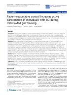
Current Methodology to Develop Custom-Fit AFOs
Creating a custom-fit AFO is a laborious and time-
intensive manual process performed by skilled orthotists.
This process is depicted in Figure 1 and can take up to
4 hours of fabrication time per unit for an experienced
technician. Once the orthotist has determined the con-
figuration and orientation of the subject’ s anatomy for
corrective measures, the form is captured by wrapping a
sock and casting the leg (Figure 1a). Markings are
drawn at key locations onto the sock surface which
Mavroidis et al. Journal of NeuroEngineering and Rehabilitation 2011, 8:1
/>Page 2 of 11
instruct technicians later on about where to perform
corrective modifications. Once the cast has set
(Figure 1b), it is cut away along the anterior contour, in
line with the tibia (Figure 1c). The open edge of the cast
is filled and plaster is poured into the leg cavity. Starting
at the heel, key surfaces are built outwards with plaster
by embedding staples corresponding to surface markers
(Figure 1d). Once the leg bust has been modified, pre-
heated thermoplastic is vacuum formed around the plas-
ter (Figure 1e). Once cool, the unwanted plastic is cut
away, leaving an uneven 1/4” deep gash in the modified
leg bust, and requiring edges on the AFO to be ground
down & smoothed (Figure 1f). T he back vertical surface
of the removed AFO is loaded and bent forward by the
technician to check for even s play during weight bear-
ing. Should the need arise to re-fabricate a patient ’s
AFO, the gash in the bust must be repaired before ther-
moforming can take place. Due to warehousing consid-
erations, most leg busts in clinics are not kept f or more
than typically 2 months, so for each patient refitting
(typically occurring every other year), the whole process
must start from the beginning.
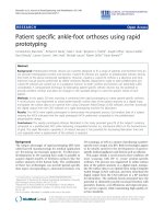
Methods
The main steps of the proposed method are: a) position-
ing the patient in a way that is suitable for scanning and
taking the scan using a 3D scanner that is capable of
creating a full 3D point cloud of the ankle-foot complex
(or any other joint of interest); b) processing and manip-
ulating the data from the scan to create the computer
model of the desired orthosis including performing
design modifications to optimize the shape of the ortho-
sis according to the clinical needs; c) fabricating the
custom-fit orthosis using a RP machine. Figu re 2 illus-
trates the process.
To show that the proposed technique can lead to
manufacturing an AFO comparable to a prefabricated
one, we chose a posterior leaf spring AFO (Type C-90
Superior Posterior Leaf Spring, AliMed, Inc., Dedham,
MA) as an exemplary orthotic device to be matched by
using the proposed RP-based technique [15]. The RP
implementation of the posterior leaf spring AFO used a
3D FaceCam 500 from Technest Inc. [16] f or acquiring
the data of the human’ s anatomy and a Viper Si2
SLA machine from 3D Systems Inc. for layered manu-
facturing [17].
3D Scanning
The 3D FaceCam 500 scanner from Technest Inc cap-
tures three images (two for surface shape, one for color)
with a resolution of 640 × 480 pixels. During a scan, a
pattern of colored light is projected onto the target sur-
face. The reflected light from this pattern is captured by
camera lenses at two different locations, which will later
be used to reconstruct the shape digitally. In order to
get the most accurate data possible from the 3D scans, a
procedure was developed for sc anning a subject’sankle
and foot. The design required data from below the knee
and to the posterior of the leg and also the ventral side
of the foot. The camera locations for scans are dictated
by its range and field of vie w, which directly impact the
quality of the data. The scanning operation was broken
down into 3 vertical images of the ankle region and
3 images of the bottom of the foot whilst the subject
was not load bearing. A white background was placed
around the leg to differentiate the subject’slegfrom
A
B
C
D
E
F
Figure 1 Traditional fabrication process of an ankle foot orthosis for a patient.
Mavroidis et al. Journal of NeuroEngineering and Rehabilitation 2011, 8:1
/>Page 3 of 11
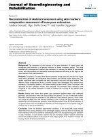
extraneous data. Figure 3 shows the position of the cam-
era for each of the scans of the ankle-foot complex
while load bearing and one view of the subject’s foot
and ankle as seen by the 3D scanner. The non-load
bea ring scans were taken with the knee at about 90 deg
and the shank in a vertical position.
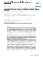
Software
The acquired scans were post-processed using the soft-
ware Rapidform [18]. This software was used to clean
and convert the scans by removal of unwanted points
and meshing of the point cloud into a single shell. Fig-
ure 4 illustrates this process.
The process began with removing redundant data
points (Figure 4). This includes data from the parts of
the leg that were not needed as well as mismatching
surfaces and data from the floor or background for each
captured view. The points within each cloud were then
connected to each other with three-sided polygons to
create a surface mesh. The individual surface meshes
A
B
C
D
F
Figure 2 Process used to fabricate the proof of concept AFOs.
A
B
Figure 3 Positioning of the foot during laser scan ning. (A) Schematic of the setup and procedure used to scan the ankle of the subject.
Note the relative positions of the cameras. (B) Lateral aspect of the foot and ankle as seen from the perspective of the right camera of the
scanner.
Mavroidis et al. Journal of NeuroEngineering and Rehabilitation 2011, 8:1
/>Page 4 of 11
were aligned and merged to create one complete surface
model of the ankle-foot complex. The polygon surface
curvature was smoothened and edges then trimmed
with a boundary curve. This surface was then offset to
prevent the fa bricated AFO from over-compressing the
subject’s l eg. The offset surface was extruded to a thick-
ness of 3 mm as typically done for fitting of standard
AFOs [15]. Once completed, the model was exported
from Rapidform as a STL file.
Rapid Prototyping
The model was manufactured using the 3D Systems
Viper Si2 SLA machine [17]. This system uses a solid
state Nd YVO
4
laser to cure a liquid resin. STL files
were prepared with 3D Lightyear for part an d platform
settings, and Buildstation to optimize the machine’ s
configuration.
The effectiveness of using RP for the a pplication at
hand is largely dependent on material properties. The
prefabricated AFO selected for the study (i.e. the one we
attempted to match using the proposed methodology
based on RP) was the Type C-90 Superior Posterior
Leaf Spring from AliMed [15]. This AFO comes in a
pre-determined range of sizes of injection molded
polypropylene.
Two different AFOs, each fabricated with a different
material, were built using the Viper SLA machine. The
first material was the Accura 40 resin that produced a
rigid AFO while the second AFO was more flexible as it
was manufactured using the DSM Somos 9120 Epoxy
Photopolymer. This resin is biocompatible for superficial
exposure and offers good fatigue properties relative to
the polypropylene [19]. Material properties are com-
pared in Table 1.
Gait Analysis
Gait studies were conducted at Spaulding Rehabilitation
Hospital, Boston, MA using a motion capture system.
We collected data from a healthy subject (the one for
which scans were taken in order to manufacture the
AFO) walking without an AFO, walking with the above-
mentioned standard, prefabricated AFO, and walking
with each of the AFOs manufactured using the
Figure 4 Flow diagram of the post-scanning software procedures.
Table 1 AFO material properties
Description Unfilled
Polypropylene
Accura SI 40 Somos
®
9120 UV
Tensile Strength
(MPa)
31 - 37.2 57.2 - 58.7 30 -32
Elongation (%) 7 - 13 4.8 - 5.1 15 - 25%
Young’s Modulus
(GPa)
1.1 - 1.5 2.6 - 3.3 1.2 - 1.4
Flexural Strength
(MPa)
41 - 55 93.4 - 96.1 41 - 46
Flexural Modulus
(MPa)
1172 - 1724 2836 - 3044 1310 - 1455
a) polypropylene used with the standard, prefabricated AFO); b) Accura SI 40
used with the rigid RP AFO and c) the epoxy photopolymer Somos 9120 used
with the flexible RP AFO.
Mavroidis et al. Journal of NeuroEngineering and Rehabilitation 2011, 8:1
/>Page 5 of 11
proposed RP-based technique. The subject wore the
AFOs on t he right side. Four different conditions were
therefore tested: 1) with sneakers and no AFO (No
AFO) ; 2) with the standard, prefabricated polypropylene
AFO (Standard AFO); 3) with the rigi d AFO made w ith
the Accura 40 resin (Rigid RP AFO), and 4) with the
flexible AFO made from the Somos 9120 resin (Flexi ble
RP AFO).
Reflective markers were placed on the f ollow ing ana-
tomical landmarks: bilateral anterior superior iliac
spines, posterior superior iliac spines, lateral femoral
condyles, lateral malleoli, second metatarsa l heads, and
the calcanei (Figure 5). Additional markers were also
rigidly attached to wands and placed over the mid-
femur and mid-shank. The subject was instructed to
ambulate along a walkway at a comfort able speed for all
of the walking trials. An 8-camera motion capture sys-
tem (Vicon 512, Vicon Peak, Oxford, UK) recorded the
three-dimensional trajectories of the reflective markers
during the walking trials. Two force platfor ms (AMTI
OR6-7, AMTI, Watertown, MA) em bedded in the walk-
way recorded the ground reaction forces and moments.
Data was gathered at 120 Hz. Ten walking trials with
foot contacts of each foot onto the force platforms were
collected for each testing condition.
Gait parameters derived from the walking trials included
spatio-temporal parameters and kinematics and kinetics of
the hip, knee and ankle of each leg in the sagittal plane.
Kinematics (joint angles) and kinetics (joint moments and
powers) were e stimated using a standard model (Vicon
Plug-in-Gait, Vicon Peak, Oxford, UK).
Results
AFO Fabrication
The prototype built using the Acura 40 resin is shown
in Figure 6. The model had to be built in an incline d
orientation since it did not fit sideways (Figure 6A). The
build cycle consisted of 2,269 layers of resin and was
built in the total time of 16.7 hours due to the large
z-build dimension. Fitting of the rigid RP AFO proto-
type was excellent.
A second prototype was built from the same STL
model file but using a more flexible SOMOS 9120 resin.
The dimensions of the final prototype AFO and the pre-
fabricated AFO were very closely matched. The weight
of the flexible RP AFO was lower by 21%. Figure 7A
shows the flexible RP AFO. Figure 7B shows the flexible
RP AFO being worn by the subject recruited for the
scanning. The optimal fit of the AFO geometry t o the
human subject anatomy was evident from vis ual inspec-
tion and the subject expressed great comfort whilst
wearing it.
Testing and Validation
Analysis of the spatio-temporal gait parameters showed
that the subject walked very consistently across the four
testing conditions. Differences between the conditions
based on the range (minimum and maximum values) of
each parameter for the left and right leg were less than
10%. When comparing only the right side, on which the
AFOs were worn, the differences between conditions for
each of the parameters reduced to 5% or less (Table 2).
This indicates that observed changes in the kinematics
and kinetics of gait are likely due to differences in the
properties and behavior of the AFOs rather than to fluc-
tuations in speed or step length of the subject during
the walking trials for each condition.
The ankle kinematics showed the effect of the three
tested AFOs. Figur e 8A shows the mean plantarflexion-
dorsiflexion trajectory of the right ankle for one gait
cycle collected during the walking trials performed with-
out AFO. This pattern is typical of individuals without
gait abnormalities. For the sake of analyzing the ankle
biomechanics, we divided the gait cycle into four sub-
phases (see Figure 8A): controlled plantarflexion (CP)
after initial contact, controlled dorsiflexion (CD) as the
lower leg progresses forward over the foot, power plan-
tarflexion during push-off (PP), and dorsiflexion during
swing ( SD) to assist foot c learance. The use of an AFO
affected the ankle trajectory during these phases (see
Figure 8B). Using the above-defined sub-phases, we
compared the movement of the right ankle for the
four testing conditions (see Figure 8B) to assess the
Figure 5 Position of t he reflective mark ers used during the
gait analyses.
Mavroidis et al. Journal of NeuroEngineering and Rehabilitation 2011, 8:1
/>Page 6 of 11
performance of the three AFOs (prefabricated AFO,
Flexible RP AFO, and Rigid RP AFO) and compare the
observed kinematic trajectories with the data gathered
without using an AFO.
Figure 8B shows that the ankle is slightly more plan-
tarflexed at initial contact when wearing no AFO com-
pared to wearing an AFO, and that for each of the AFO
conditions initial contact was made with t he ankle-foot
complex in a more neutral position. This is likely due to
the AFOs being made from castings and scans, respec-
tively, of the subject’s foot set in a neutral position. Dur-
ing controlled plantarflexion (CD) the ankle showed a
similar range of motion (RoM) for each of the AFOs
with the standard, prefabricated AFO allowing slightly
more plantarflexion compared to the RP AFOs (Figure
8C). This may be due to greater compliance of the
polypropylene material from which the standard AFO
was made.
During the phase of controlleddorsiflexion(CD),the
standard AFO allowed more RoM compared to the two
RP AFOs, which performed similarly (Figure 8D). This
greater RoM was due to a combination of greater plan-
tarflexion during the CP phase and also greater dorsi-
flexion during the CD phase.
The ankle showed the greatest RoM during the power
plantarflexion (PP) phase at push-off when the subject
was wearing no brace since the movement of the ankle
was not restricted by an AFO. When weari ng the AFOs,
the amount of plantarflexion was substantially decreased
(Figure8B)whiletheRoMduringthePPphasewas
slightly greater for the standard AFO compared to the
two RP AFOs (Figure 8E).
B
A
Figure 6 Rigid RP AFO. (A) Example of the build platform. (B) Completed rigid RP AFO prototype.
B
A
Figure 7 Flexible RP AFO. A) The flexible RP AFO. (B) The positioning and fitting of the flexible RP AFO to the leg of the subject.
Mavroidis et al. Journal of NeuroEngineering and Rehabilitation 2011, 8:1
/>Page 7 of 11
In the final phase of dorsiflexion during swing (SD),
the ankle showed the greatest RoM when it was not
restricted by an AFO, while the three AFO testing con-
diti ons showed lower but similar ranges of motion (Fig-
ure 8F). This was partly due to the reduced amount of
plantarflexion achieved during the PP phase. Impor-
tantly the two RP AFOs enabled a similar amount of
ankle dorsiflexion at the end of swing as that allowed by
the standard AFO (Figure 8B).
The kinetics of the ankle (joint moments and powers)
also revealed that the two RP AF Os perfor med similarly
to the standard AFO. Figure 9A shows the mean right
ankle flexion/extension moment during the walking
trials for each testing condition. It is evident that t he
ankle moment profile for the three AFOs was similar.
The peak flexor moment for each AFO testing condition
was slightly smaller than that f or the no-AFO testing
condition ( Figure 9B). When comparing the profiles of
ankle power, we observed similarities across the thre e
AFO testing conditions (Figure 10) with a general
reduction in peak power generation compared to the
no-AFO condition. This attenuated peak power is likely
due to t he restricted plantarflexion of the ankle during
push off imposed by the AFOs.
Overall, when comparing the three AFOs, it was clear
that they performed similarly in terms of controlling
ankle kinematics and kinetics during the gait cycle.
The f lexible RP AFO performed almost identically to
the standard AFO. Both required l ess ankle power than
normal ( i.e. with no A FO). The rigid AFO results
Table 2 Mean (± SD) spatiotemporal gait parameters of the right side for the 4 testing conditions
Parameter No AFO Standard AFO Flexible RP AFO Rigid RP AFO
Walking speed (m/s) 1.49 ± 0.05 1.46 ± 0.02 1.44 ± 0.05 1.50 ± 0.06
Step length (m) 0.79 ± 0.02 0.79 ± 0.01 0.79 ± 0.03 0.82 ± 0.03
Double support time (s) 0.22 ± 0.02 0.24 ± 0.01 0.24 ± 0.01 0.23 ± 0.01
20
CP CD PP SD
AB
g
)
0
10
20
No AFO
Standard AFO
Flexible RP AFO
Rigid RP AFO
n
gle (de
g
-20
-10
A
nkle A
n
0 20406080100020406080100
Gait Cycle (%) Gait Cycle (%)
A
C
D
E
F
g
)
0
10
20
C
D
E
F
R
OM (de
g
-20
-10
Ankle
R
Control Plantarflexion Control Dorsiflexion Power Plantarflexion Swing Dorsiflexion
No AFO Standard AFO
Flexible RP AFO
Rigid RP AFO
Figure 8 Ankle kinematics during the 4 testing conditions. (A) Average profile of ankle plantarflexion-dorsiflexion for five gait cycles of the
No AFO condition (i.e. shoes only). The larger dashed vertical line represents the instance of toe-off and the lighter dashed vertical lines
separate four different sub-phases of ankle function during the gait cycle (see text for details). (B) Average profiles of ankle plantarflexion-
dorsiflexion for five gait cycles of the four testing conditions. Panels C - F show the mean (± SD) range of motion (RoM) in ankle plantarflexion-
dorsiflexion for the four sub-phases illustrated in panel A for each of the four AFO conditions.
Mavroidis et al. Journal of NeuroEngineering and Rehabilitation 2011, 8:1
/>Page 8 of 11
showed that this testing condition was associated with
high ankle power; most likely b ecause the rigid AFO
provided resistance to bending that the subject had to
overcome. Despite differen ces among AFO’ s, it was
noted that the ch ange in ankle power was still relatively
small, and that increased material flexib ility would have
been likely to help improving performance.
Conclusions
In this paper, we presented a process to combine state
of the art 3D scanning hardwar e and software technolo-
gies for human surface anatomy with advanced RP tech-
niques so that novel custom made orthoses and
rehabilitation devices can be rapidly produced. Two cus-
tom-fit AFOs were rapidly prototyped to demonstrate
1.5
2
.
0
m
ent
No AFO
Standard AFO
Flexible RP AFO
Rigid RP AFO
A
0
0.5
1.0
n
kle Mo
m
(Nm)
-0.5
0
02040608010
0
Gait Cycle (%)
A
n
1.5
2.0
kle
(
Nm)
B
0
0.5
1.0
Peak An
M
oment
(
-0.5
0
M
Peak Flexor
Moment
Peak Extensor
Moment
No AFO
Standard AFO
Flexible RP AFO
Rigid RP AFO
Figure 9 Ankle kinetics during the 4 testing conditions. (A) Average profiles of ankle flexor-extensor moments for five gait cycles of the four
testing conditions. (B) Mean (± SD) peak ankle extensor and flexor moments for the four testing conditions.
Mavroidis et al. Journal of NeuroEngineering and Rehabilitation 2011, 8:1
/>Page 9 of 11
the proposed process. Preliminary biomechanical data
from gait analyses of one subject wearing the AFOs
indicated that the RP AFOs can match the performance
of the standard, prefabricated, polypropylene design.
This new platform technology for developing custom-fit
RP orthoses has the potential to provide increased free-
dom with geometric features, cost efficiencies and
improved practice service capacities while maintaining
very high quality-of-service standards. In the long run,
this technology aims at bringing the manufacturing of
orthoses from the current manual labor/expert crafts-
man’s skills to a 21
st
century computerized design pro-
cess. The proposed technology has the potential for
increasing the numbers of patients ser viced per year per
4
No AFO
Standard AFO
Flexible RP AFO
Rigid RP AFO
w
er
A
0
2
A
nkle Po
w
(W)
-2
02040608010
0
Gait Cycle (%)
A
4
kle
W
)
B
0
2
Peak An
Power (
W
-2
Peak Power
Absorption
Peak Power
Generation
No AFO
Standard AFO
Flexible RP AFO
Rigid RP AFO
Figure 10 Ankl e power during the 4 testin g conditions. (A) Average profiles of ankle powers for five gait cycles of the four testing
conditions. (B) Mean (± SD) peak power absorption and power generation at the ankle for the four testing conditions.
Mavroidis et al. Journal of NeuroEngineering and Rehabilitation 2011, 8:1
/>Page 10 of 11
orthotist while reducing overall t he orthosis fabrication
cost and time.
Author details
1
Department of Mechanical & Industrial Engineering, Northeastern University,
360 Huntington Avenue, Boston, MA, 02115, USA.
2
Department of Physical
Medicine and Rehabilitation, Harvard Medical School, Spaulding
Rehabilitation Hospital, 125 Nashua Street, Boston, MA, 02114, USA.
3
Polymesh LLC, 163 Waterman Street Providence, RI 02906-3109.
4
IAM
Orthotics & Prosthetics, Inc., 400 West Cummings Park, Suite 4950, Woburn,
MA, 01801, USA.
5
Harvard-MIT Division of Health Sciences and Technology,
77 Massachusetts Ave., Cambridge, MA, 02139, USA.
Authors’ contributions
CM, PB, ML: conceived the study and participated in the design and data
analysis.
RGR, MLS, AC, KG, LG, SS: carried out the design, fabrication, testing of the
RP AFOs.
BLP: participated in the testing of the RP AFOs and performed the data
analysis.
JD, RD: participated in the design and data analysis.
All authors read and approved the final manuscript.
Competing interests
The authors declare that they have no competing interests.
Received: 1 April 2010 Accepted: 12 January 2011
Published: 12 January 2011
References
1. Chelule K, Coole T, Chesire D: Fabrication of medical models from scan
data via rapid prototyping techniques. Proceedings of the 2000 Conference
on Time Compression Technologies Cardiff International Arena, UK; 2000.
2. CC Kai, Meng CS, Ching LS, Teik LS, Aung SC: Facial prosthetic model
fabrication using rapid prototyping tools. Integrated Manufacturing
Systems 2000, 11(1):42-53.
3. Hieu LC, Zlatov N, Sloten JV, Bohez E, Khanh L, Binh PH, Oris P, Toshev Y:
Medical rapid prototyping: applications and methods. Assembly
Automation 2005, 25(4):284-292.
4. Zollikofer CPE, Ponce de Leon MS: Tools for rapid prototyping in the
biosciences. IEEE Computer Graphics and Applications 1995, 15(6):48-55.
5. Noorani R: Rapid Prototyping: Principles and Applications John Wiley & Sons
Inc. Hoboken;; 2006.
6. Webb PA: A review of rapid prototyping (RP) techniques in the medical
and biomedical sector. Journal of Medical Engineering & Technology 2000,
24(4):149-153.
7. Sinn DP, Cillo JE, Miles BA: Stereolithography for craniofacial surgery. The
Journal of Craniofacial Surgery 2006, 17(5):869-875.
8. Chua CK, Leong KF, KH Tan, Wiria FE, Cheah CM: Development of tissue
scaffolds using selective laser sintering of polyvinyl alcohol/
hydroxyapatite biocomposite for craniofacial and joint defects. Journal of
Material Science: Materials in Medicine 2004, 15:1113-1121.
9. Herbert N, Simpson D, Spence WD, W Ion: A preliminary investigation into
the development of 3-D printing of prosthetic sockets. Journal of
Rehabilitation Research & Development 2005, 42:141-146.
10. Rogers B, Bosker GW, Faustini MF, Walden G, Neptune RR, Crawford RH:
Variably Compliant Transtibial Prosthetic Socket Fabricated Using Solid
Freeform ‘a case study’. Journal of Prosthetics and Orthotics 2008, 20(1):1-7.
11. Kumar V, Bajcsy R, Harwin W, Harker P: Rapid design and prototyping of
customized rehabilitation aids. Communications of the ACM 1996,
39(2):55-61.
12. Milusheva S, Tochev D, Stefanova Y, Y Toshev Y: Virtual models and
prototype of individual ankle foot orthosis. Proceedings of ISB XXth
Congress - ASB 29th Annual Meeting Cleveland, Ohio; 2005, 227.
13. Milusheva S, Tosheva E, Tochev D, Toshev Y: Personalized ankle foot
orthosis with exchangeable elastic elements. Journal of Biomechanics
2007, 40(S2):S592.
14. Faustini MC, Neptune RR, Crawford RH, Stanhope SJ: Manufacture of
passive dynamic ankle-foot orthoses using selective laser-sintering. IEEE
Transactions of Biomedical Engineering 2008, 55(2):784-790.
15. Alimed Inc.:
Type C-90 Superior Posterior Leaf Spring 2009 [http://www.
alimed.com].
16. Technest Holdings, Inc.: 3D Imaging Products [ />pdfs/3DImaging/Genex_3DSolutions_web.pdf].
17. 3D Systems Inc.: Products - SLA Systems - Viper Si2 2009 [http://
www.3dsystems.com/products/sla/viper/datasheet.asp].
18. Rapidform Inc.: The Standard Software for 3D Scanning 2009 [http://www.
rapidform.com/].
19. 3D Systems Inc.: Products - Accura 40 SLA Resin 2009 [http://
www.3dsystems.com/products/datafiles/accura/datasheets/DS-
Accura_25_SL_material.pdf].
doi:10.1186/1743-0003-8-1
Cite this article as: Mavroidis et al.: Patient specific ankle-foot orthoses
using rapid prototyping. Journal of NeuroEngineering and Rehabilitation
2011 8:1.
Submit your next manuscript to BioMed Central
and take full advantage of:
• Convenient online submission
• Thorough peer review
• No space constraints or color figure charges
• Immediate publication on acceptance
• Inclusion in PubMed, CAS, Scopus and Google Scholar
• Research which is freely available for redistribution
Submit your manuscript at
www.biomedcentral.com/submit
Mavroidis et al. Journal of NeuroEngineering and Rehabilitation 2011, 8:1
/>Page 11 of 11