Báo cáo hóa học: " Prosthetic finger phalanges with lifelike skin compliance for low-force social touching interactions" doc
Bạn đang xem bản rút gọn của tài liệu. Xem và tải ngay bản đầy đủ của tài liệu tại đây (2.01 MB, 11 trang )
JNER
JOURNAL OF NEUROENGINEERING
AND REHABILITATION
Prosthetic finger phalanges with lifelike skin
compliance for low-force social touching
interactions
Cabibihan et al.
Cabibihan et al. Journal of NeuroEngineering and Rehabilitation 2011, 8:16
(30 March 2011)
RESEARCH Open Access
Prosthetic finger phalanges with lifelike skin
compliance for low-force social touching
interactions
John-John Cabibihan
*
, Raditya Pradipta and Shuzhi Sam Ge
Abstract
Background: Prosthetic arms and hands that can be controlled by the user’s electromyog raphy (EMG) signals are
emerging. Eventually, these advanced prosthetic devices will be expected to touch and be touched by other
people. As realistic as they may look, the currently available prosthetic hands have physical properties that are still
far from the characteristics of human skins because they are much stiffer. In this paper, different configurations of
synthetic finger phalanges have been investigated for their skin compliance behaviour and have been compared
with the phalanges of the human fingers and a phalanx from a commercially available prosthetic hand.
Methods: Handshake tests were performed to identif y which areas on the human hand experience high contact
forces. After these areas were determined, experiments were don e on selected areas using an indenting probe to
obtain the force-displacement curves. Finite element simulations were used to compare the force-displacement
results of the synthetic finger phalanx designs with that of the expe rimental results from the human and prosthetic
finger phalanges. The simulation models were used to investigate the effects of (a) varying the internal topology of
the finger phalanx and (b) varying different materials for the internal and external layers.
Results and Conclusions: During handshake, the high magnitudes of contact forces were observed at the areas
where the full grasping enclosure of the other person’s hand can be achieved. From these areas, the midd le
phalanges of the (a) little, (b) ring, and (c) middle fingers were selected. The indentation experiments on these
areas showed that a 2 N force corresponds to skin tissue displacements of more than 2 mm. The results from the
simulation model show that introducing an open pocket with 2 mm height on the internal structure of synthetic
finger phalanges increased the skin compliance of the silicone material to 235% and the polyurethane material to
436%, as compared to a configuration with a solid internal geometry. In addition, the study shows that an
indentation of 2 N force on the synthetic skin with an open pocket can also achieve a displacement of more than
2 mm, while the finger phalanx from a commercially available prosthetic hand can only achieve 0.2 mm.
Background
It is not very often that our days pass by without any of
the following touch-related experience: a handshake
from a colleague, a caress from a spouse, a hug, a pat
on the back or high fives with pals. As social beings, the
need to touch and be touched is inherent among us.
Indeed, it is through touch that distinct emotions such
as anger, fear, disgust, love, gratitud e and sympathy can
be communicated [1]. Howe ver, these typical exchanges
of social touching may be limited for those who have
lost their hands due to an accident, disease or war.
Prosthetic arms and hands that can be controlled by
the electromyography (EMG) signals are emerging [2,3].
Kuiken et al [4] demonstrated a surgical technique called
targe ted muscle reinnervation th at transfers resi dual arm
nervestoalternativemusclesites.Theyhavedemon-
strated that this technique enables the subjects to per-
form real-time control of motorized shoulders, elbows,
wrists and hands for grasping soft and bri ttle objects, like
grapes or eggs, with enough force to hold them without
crushing them. On the commercial front, Touch Bionics’
lightweight and fully articulated prosthetic hand, the
* Correspondence:
The Social Robotics Laboratory, Interactive and Digital Media Institute and
Department of Electrical and Computer Engineering, The National University
of Singapore, Singapore
Cabibihan et al. Journal of NeuroEngineering and Rehabilitation 2011, 8:16
/>JNER
JOURNAL OF NEUROENGINEERING
AND REHABILITATION
© 2011 Cabibihan et al; licensee BioMed Central Ltd. Th is is an Open Access article distributed under the terms of the Creative
Commons Attribution License (http://creativeco mmons.org/lic enses/by/2.0) , which permits unrestricted use, distribution, and
reproduction in any medium, provided the original work is properly cited.
i-LIMB Hand [5], can now enable the amputees to per-
form gestures and various gripping movements (e.g.
power, precision, index point, etc).
Eventually, these advanced prosthetic devices will be
expected to perform affective touches on other people.
This paper focuses on replicating the softness of the
skin tissue on the human hand during social touching
interactions. Particularly, different configuration s of syn-
thetic finger phalanges were investigated with the goal
to replicate the softness of the human finger phalanges
that is felt during handshakes and light touches. Here,
softness is defined as the perceptual corre late of skin
compliance or the amount of deformation caus ed by an
applied force [6].
Aside from the functional limitations, the loss of
hands implies negative psychological and emotional con-
sequences on the person and to those around him or
her. Using focus group methodology on 14 participants
who have lost a limb, Gallagher and MacLachlan [7]
found that self-image, social, physical and practical con-
cerns are some of the key factors that are important in
the adjustment process. They revealed that a common
response in seeing the prosthesis for the first time was
“extreme shock and disappointment”. On the question
of “What do you find most difficult to deal with having
an artificial limb?” some participants expressed concern
about the impression they made on others. O ne woman
describedthateveninherownhomeshefoundit
impossible for her to relax without her artificial limb on,
anticipating that an unexpected visitor may arrive. Gal-
lagher and MacLachlan noted that the common senti-
ment of the participants is to appear a nd be ‘ normal’
again. With regard to social interactions, many of the
participants encountered uncomfortable situations,
wherein they stated that other people’s reactions varied
from patronization to complete shock.
Under similar circumstances and with limited alter-
natives for replacement limbs, it is understandable that
depression can be one of the conditions associated
with limb loss. Gallag her and MacLachlan [8] found
that the rates of clinical depression range from 21 to
35 percent. Rybarczyk et a l [9] highlighted five key
issues that clinicians sho uld attend to: 1) amputation is
a diverse disability; 2) discrimination by others; 3) self-
stigma; 4) feeling vulnerable to victimization; and
5)theroleofvalues,meaningandperspectiveinposi-
tive adjustment. Using semi-structured email and face-
to-face interviews on 35 prosthesis users, Murray [10]
concludedthatprosthesisuse plays a social role in the
lives of people with l imb loss or a bsence. He found
that the ability to conceal such use enabled partici-
pants t o ward off social stigmatisation that could result
into better integration into the society and the reduc-
tion o f emotional problems.
Given the many issues surrounding limb loss or
absence, many researchers have been addressing the
technical issues in sensing, contr ol and functi onality of
prosthetic arms and hands with some success (e.g.
[11-16]). In terms of appearance, the current upper limb
prosthetics can now be created to be indistinguishable
from the natural ones with the accurate mimicry of the
skin tone, hairs and pores (e.g. [17,18]). H owever, these
are sti ll stiff when touched. The availability of artificial
hands with lifelike appearance but not lifelike softness
poses a perception problem t o the person that these
hands will touch. As such, finding synthetic materials
that have similar properties to that of the human skin
becomes important [19-21].
Among the social touches mentioned, the handshake
remains one of the more acceptable gestures in many cul-
tures . We conducted experiments to determine the areas
of frequent contact during handshakes and the corre-
sponding forces. After determining these areas, another
set of experiments were done to indent a probe on th e
hands to obtain the amount of displacement that results
from the application of forces during hand shake contact.
We then used Finite Element (FE) simulations to find syn-
thetic skin designs that have similar force-displacement
(i.e. skin compliance) characteristics to the human hand.
The model was used to investigate the effects of (i) varying
the internal topology of the finger phalanx and (ii) varying
different materials for the intern al and exte rnal layers.
Comparisons were done on the skin compliance beha-
viours of the finger phalanges of the human hand, the pha-
lanx of a commercially available prosthetic hand and the
synthetic skin design with open pockets.
Materials and methods
Handshake experiments
Handshake experiments were performed to investigate
the typical range of contact forces and to find out which
areas on the human hand have high contact forces dur-
ing handshake. The experiments were limited to male-
to-male handshake in light of the earlier findings in [22]
that handshakes are more frequent in male-to-male
pairs than in female-to-female or male-to-female pairs.
Tactile force sensors were attached to the right hand of
themaleexperimenterbeforeheperformedaseriesof
handshakes with the test subje cts. The force sen sors
(FingerTPS, Pressure Pr ofile Systems, USA) are made of
tactile pads that detect changes in capacitance when the
upper and lower tactile pads come into contact.
Upon shakin g hand with the test subjects, the forces
exerted on the experimenter’ shandmakethesepads
touch each other, resulting into changes in the sensors’
capacitance values. It would then be possible to measure
the magnitude of the exerted forces. The se nsors were
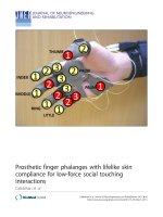
placed on eighteen areas on the experimenter’shand.
Cabibihan et al. Journal of NeuroEngineering and Rehabilitation 2011, 8:16
/>Page 3 of 11
These included all the phalanges of the fingers, the two
areas on the palm and the two areas on the b ack of the
palm. As confirmed by pre-tests, these were the areas
where contact can occur during handshake. The loca-
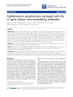
tions o f the sensors and their naming conventions are
shown in Figure 1.
There w ere 30 male test subjects who participated in
this handshake experiment. All of them were students
or researchers at the National University of Singapore
(NUS). Each of the test subjects were asked to perform
a casual handshake with the experimenter. Prior to
experiment, the experimenter was trained to give a neu-
tral handshake, in which he kept his grasping force at a
minimum and waited for the handshake partner to initi-
ate the contact. A similar protocol of having a neutral
handshake early in the sequence was carried out by
Chaplin et al [23] to establish the relationship between
handshakes and personality. The data on the experimen-
ter and the experimental subjects are s hown in Table 1.
The test subjects were reimbursed for their partici pa-
tion. Approval for the h andshake experimental protocol
was granted by the NUS Institutional Review Board.
Indentation experiments on the human and prosthetic
hands
In order to obtain the data to compare our simulation
results with, indentation experiments were done on the
phalanges where high contact forces occurred as
revealed by the handshake experiments. The middle
phalanges of the little, ring and middle fingers were cho-
sen as the target sites. The choice was made for two
reasons. First, these phalanges have similar functional
roles in the context of the handshake; they support the
lower part of the other person’s hand during the grasp.
Second, these phalanges have geometrical similarities
and modelling them can be done with relative ease. We
were also interested in seeing whether there are signifi-
cant differences on the force-displacement data when
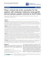
the hand lies in a flat position (Figure 2a) and when the
fingers are in a curled position (Figure 2b). A hand in a
flat position can represent l ight touches to another
person while fingers in a curled position can represent
the hand orientation during handshake. Additionally, we
wanted to know how the force-displacement data from
the phalanx of a commercially available prosthetic hand
compare with the human skin and the synthetic skin
that we are investigating. We obtained a product sample
of a prosthetic hand (Silicone Cosmetic Hand Model
102L, Regal Prosthesis Ltd, Hon g Kong) being sold at a
local prosthetics shop. We indented this prosthetic hand
at the same locations of interest (Figure 2c).
There w ere 10 male test subjects who participated in
the hand indentation experiment. The data of these sub-
jects are shown in Ta ble 2. A testing mac hine (Micro-
Tester™, Instron, UK), with a load cell limit of 5 N, was
employed to make indentations on the finger phalanges.
A specia lly fabricated brass indenter, with an indenting
area of 20 mm × 10 mm, was slotted into the load cell.
For the flat-hand position, the hand was positioned
above a mould with the palm facing upwards. For the
curled-fingers position, the hand was placed on a mould
that can constrain the hand in a typical han dshake posi-
tion (Figure 2b Inset). The mould was prepared with
crystalline-silica free alginate (Alja-Safe
®
,Smooth-On
Inc., USA). The surface of the finger phalanx of interest
was placed in a normal position under the indenter. The
indenter was then lowered until the force read-out from
the testing machine reached approximately 0.05 N. This
is negligibly small but is sufficient enough to verify that
the indenter had contacted the finger phala nx. For each
subject, all the test areas were indented with a ramp
speed of 0.5 mm/s u nder a force of up to 2 N for the
middle phalanges of the little, ring and m iddle fingers.
Figure 1 Location and naming convention of the force sensors
on the hand (a) On the surface of the palm and (b) Back of
the hand.
Table 1 Data for the Experimenter and Subjects (n = 30)
Experimenter Subjects (Mean ± Std Dev)
Age 22 26.35 ± 3.36
Height (cm) 175 173.42 ± 4.37
Weight (kg) 70 65.65 ± 8.57
Hand Length (mm) 190 187.50 ± 11.37
Hand Width (mm) 88 89.53 ± 6.80
Figure 2 Setup for the indentation experiment s (a) Flat-hand
position, (b) Curled-fingers position, and (c) Prosthetic hand
indentation. The Inset in (b) shows how the mould was prepared
to restrict the hand in a typical handshake posture.
Cabibihan et al. Journal of NeuroEngineering and Rehabilitation 2011, 8:16
/>Page 4 of 11
Approval for the indent ation experiment al protocol was
similarly granted by the NUS Institutional Review Board.
Finite element modelling
This section is composed of three sub-sections that
describe the synth etic skin samples, the constit utive
equations and the numerical simulations.
Synthetic skin samples
The skin materials for prosthetic and robotic fingers in
[11,24] were selected for this paper. Samples of silicone
(GLS 40, Prochima, s.n.c., Italy) and polyurethane (Poly
74-45, Polytek Devt Corp, USA) were previously charac-
terized in [19] for their viscoelastic and hyperelastic
behaviours. The silicone sample has a Shore A value of
11whilethepolyurethanesamplehasavalueof45.
A lower value indicates a low resistance to an indenter
in a standard durometer test. From the durometer
values above, the selected silicone material is softer as
compared to the polyurethane material.
Constitutive equations
The synthetic skins were assumed to behave with hyper-
elastic and viscoelastic properties. As such, the total
stress was made equivalent to the sum of the hyperelas-
tic (HE) stress and the viscoelastic (VE) stress such that:
σ
(
t
)
= σ
HE
(
t
)
+ σ
VE
(
t
)
(1)
where t is the time. A strain energy function, U,
defined in Storakers [25] for highly compressible elasto-
mers was used to describe the hyperelast ic behaviour of
the synthetic materials. This ha s been found to achieve
good fits on the experimental data of synthetic materials
[19] and it was likewise implemented in a human finger-
tip model in [26]. The function is given as:
U =
N
i
=1
2μ
i
α
2
i
λ
α
i
1
+ λ
α
i
2
+ λ
α
i
3
− 3+
1
β
(J
−α
i
β
− 1)
(2)
where μ
i
denote the shear moduli, a
i
are dimension-
less material parameters, l
i
are the principal stretch
ratios, J = l
1
l
2
l
3
isthevolumeratioandN is the
number of terms used in the strain energy function. The
coefficient b determines the degrees of compressibility
in the energy function. The relationship of b to t he
Poisson’s ratio, υ,isb = υ/(1-2υ).
The hyperelastic stress is related to the strain energy
function (2) by:
σ
HB
=
2
J
F
∂U
∂C
F
T
(3)
where F is the deformation gradient and C is the right
Cauchy-Green deformation tensors.
The viscoelastic behaviour is defined below, with a
relaxation function g(t) applied to the hyperelastic stress:
σ
VE
=
t
0
˙
g(τ )σ
HE
(t − τ )d
τ
(4)
The viscoelastic m aterial is defined by a Prony series
expansion of the relaxation function [27]:
g
(t )=
1 −
N
G
i=1
g
i
(1 − e
−t/τ
i
)
(5)
where g
i
is the shear relaxation modulus ratio, τ
i
is the
relaxation time, and N
G
denotes the number of terms used
in the relaxation function. The detailed information on
how the governing equations are numerically solved have
been described in the Abaqus/CAE Theory Manual [28].
Table 3 shows the material parameters for silicone and
polyurethane. These material parameters were validated
in [19]. The validation procedures in that paper con-
sisted of having the indentation results in the finite ele-
ment models matched against the resu lts of the physical
samples of synthetic fingers that were made of silicone
and polyurethane ma terials. The resul ts from simulation
and validation experiments were in good agreement.
The FE Model and Numerical Simulations
Simulations were conducted to determine the effects of
varying (i) the internal topology and (ii) varying the mate-
rial combinations of the layers in the skin compliance
result of the synthetic finger phalanges. The three-
Table 3 Coefficients for the Synthetic Materials
i 123
Silicone (υ = 0.49)
g
i
0.015 0.044 0.029
τ
i
(sec) 0.025 0.150 0.300
μ
i
(MPa) 0.080 0.010 -
a
i
0.001 15.500 -
Polyurethane (υ = 0.47)
g
i
0.167 0.158 0.113
τ
i
(sec) 0.100 1.380 25.472
μ
i
(MPa) 0.100 0.063 -
a
i
5.500 8.250 -
Table 2 Subjects’ Data for the Indentation Experiment
(n = 10)
Subjects (Mean ±Std Dev)
Age 26.11 ± 3.28
Height (cm) 173.40 ± 4.93
Weight (kg) 68.20 ± 18.23
Hand Length (mm) 188.10 ± 6.87
Hand Width (mm) 85.01 ± 8.49
Cabibihan et al. Journal of NeuroEngineering and Rehabilitation 2011, 8:16
/>Page 5 of 11
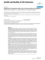
dimensional geometries of the finger phalanx designs are
shown in Figure 3. These were modelled using the com-
mercial finite element analysis software Abaqus™/St an-
dard 6.8-EF (Dassault Systemes Simulia Corp., Providence,
RI, USA). The simulations were run at the Supercomput-
ing and Visualisation Unit of the Computer Centre at the
National University of Singapore. The finger phalanx
width is 16 mm, the height is 9 mm and the thickness is
10 mm. The internal layer was made to have three topolo-
gies: a solid internal geometry (Figure 3a) and arc-shaped
pockets with 1 mm (Figure 3b) and 2 mm heights (Figure
3c). Figure 3 d shows the de tailed geometry consisting of
two layers. The external layer has a 0.8 mm thickness,
which was approximated to be the combined thickness of
the epidermis and dermis skin layers of the human finger.
The effects of the different internal topologies are to be
investigated with the use of the geometries given in
Figure 3. To in vestigate the effects of the different mate-
rial combinations, the material coefficien ts (i.e. data in
Table 3) of the external and internal layers were set in
the Abaqus™ software. For example, to have a homoge-
neous solid material of silicone, the inner and outer
layers were given the same set of mater ial coefficients; to
have silicone as the inner layer and polyurethane as the
outer layer, the material coefficients were set accordingly.
Three sets of contact interactions were specified in the
model. First, a ‘normal’ contact behaviour was applied
on the su rface of the indenting plate and the external
surface of the finger phalanx model. Next, a tie-connec-
tion was assumed for the 0.8 mm external layer and the
rest of the finger phalanx model. Lastly, a ‘normal’ con-
tact behaviour was similarly applied on the upper and
lower surfaces of the 1 mm and 2 mm pocket designs as
they come into contact due to the indenting plate.
The Abaqus™ 6.8-EF tetrahedral elements were used
in conjunction with its automatic seed mesh feature.
There were 1260 elements automatically generated for
the solid internal geometry,4838elementsforthegeo-
metry with 1 mm pocket and 3290 elements for the
geometry with 2 mm pocket. The base of the finger geo-
metry was constrained in all degrees of freedom to
represent the bone structure of the human finger.
A displacement loading condition was applied on the
rigid analytical surface that progressively indented ea ch
of the finger phalanx designs. The loading rate was
0.5 mm/sec. The results corresponding to the normal
force (i.e. RF2) and the vertical displacement (i.e. U2)
were obtained. These results will be compared to the
skin compliance data of the human finger phalanges and
theprosthetichandthatwereobtainedfromtheinden-
tation experiments.
Results and Discussion
Handshake experiments
The results of the h andshake experiments are plotted in
Figure 4. The locations of the sensors on the hand are
shown on the x-axis while the y-axis shows the force
results from the tactile sensors. High contact forces (i. e.
forces greate r than 2 N) were experienced at the palm,
back of the palm , the thumb, the proximal phalanx of the
little finger and the middle phalanges of the little, ring
and middle fingers. These phalanges are the locations
where the full grasping enclosure of the other person’ s
hand can be achieved . For the purpose of the indentation
experiments, the middle p halanges of the little, ring and
middle fingers were selected. These are henceforth
named Little2, Ring2 and Middle2, respectively.
Indentation experiments on the human hand
The forc e-displacement curves obtained from the three
test areas as well as the comparison of the skin tissue
Figure 3 Geometries of the 3D finite element model. (a) Solid
internal geometry. Internal geometry pockets of (b) 1 mm and (c) 2 mm
heights. (d) The finite element model showing the two material layers.
Figure 4 Parts of the hand with the corresponding contact
forces during handshake. The data were taken from one male
experimenter who shook hands with 30 male subjects. (a) Contact
force distribution during handshake. The highlighted areas in red in
(b) and (c) show the areas where contact forces are greater than 2 N.
Cabibihan et al. Journal of NeuroEngineering and Rehabilitation 2011, 8:16
/>Page 6 of 11
displacements at 2 N force for both the flat-hand posi-
tion and the curled-fingers position are plotted on
Figure 5. The representative data fr om one subject in
Figure 5a, 5b and 5c show that indentation forces of
2 N can result into finger tissue displacements that can
reach beyond 3 mm.
Figure 5d shows the displacements of the finger pha-
langes of the 10 subjects at 2 N load under the curled
and flat orientations. Paired-samples t-tests were con-
ducted on the displacement data of each of these flat
and curled pairs to evaluate the differences in their skin
comp liance results. There was no statis tically significant
difference found in the displacement data of the flat Lit-
tle2 (M = 3.2631, SD = 0 .8426) and curled Little2 (M =
3.7862, SD = 1.1647), t(9) = 1.6224, p = 0.1392 (two-
tailed). The mean difference in the displacement data is
0.5231 with a 95% con fidence interval ranging from
-0.2063 to 1.2527.
No statistically significant difference was observed in
the displacement dat a of the flat Ring2 (M = 3.7163, SD
= 0.4980) and curled Ring2 ( M = 3.9892, SD =1.3457),t
(9) = 0.7246, p = 0.4871 (two-tailed). The mean differ-
ence in the displacement data is 0.2729 with a 95% confi-
dence interval ranging from -0.5789 to 1.1245.
Lastly, there was a lso no statistically significant dif-
ference in the displacement data in flat Middle2 (M =
3.7452, SD = 0.6 623) and curled Middle2 (M = 3.5830,
SD = 0.7893), t(9) = -0.6169, p = 0.5526 (two-tailed).
The mean difference in the displacement data is
0.1622 with a 95% confidence interval ranging from
-0.7573 to 0.4328. In summary, these data show that
there are no significant differences in the skin
compliance of the Little2, Ring2 and Middle2 in flat
andcurledorientations.
Effect of the open pockets
Figure 6 shows the vertical displacement contours that
correspond to the 2 N indentations for the solid internal
geometry,the1mmand2mmheightopenpockets
designs. The effect o f having pockets on the finger pha-
lanx models with a single material layer are shown by
the thicker lines in Figure 7 (i.e. Silicone (SIL) and Poly-
urethane (PU)). The simulation results of the models
with solid internal geometry a re shown at the bottom
cluster in this f igure. A 2 N compressive load resulted
into 0.42 mm displacement for PU and a 0.77 mm dis-
placementforSIL.Introducinga1mmheightpocket
increased the displacement to 1.38 mm for PU and
1.72 mm for SIL. These correspond to 229% and 123%
increase in the displacement values, respe ctively, when
compared to the solid internal geometry configuration.
Having a 2 mm height pocket results into displacements
of 2.25 mm for PU and 2.58 mm for SIL, corresponding
to 436% and 235% increase, respectively, from the solid
internal geometry configuration. These results show that
having internal pockets can significantly increase the
skin compliance results of synthetic skins.
Effect of varying the layers
The human skin is tough, compliant and has self-healing
properties. Technologies that can replicate all these
properties are not yet available for prosthetic skins.
Therefore, it is important to investigate the effects of a
two-layered synthetic skin, which can give insights on
how to satisfy the r equirements for softness for social
touching interactio ns and other requirements for wear,
puncture and tear.
This sec tion describes the e ffects of having a 0.8 mm
outer layer o f one type of m aterial and an internal layer
of another material. The results are shown as the thin-
ner line types in Figure 7 (i.e. SIL Inner PU Outer and
PU Inner SIL Outer). The first four curv es clustered at
the bottom part of the figure are the simulation results
from the solid internal geometry configuration. A 2 N
compressive load for a combination of PU inner layer
Figure 5 Indentation tes t results from one of the test subjects
on a flat-hand position and a curled-fingers position at the
(a) Little2, (b) Ring2, and (c) Middle2 finger phalanges. The bars
in (d) show the comparison of the displacements at the Little2,
Ring2, and Middle2 with 2 N force indentations for 10 subjects. The
error bars represent the standard deviation.
Figure 6 F inite element simulation results showing the
displacement contours at 2 N force indentation. (a) Solid
internal geometry. Internal geometry pockets with (b) 1 mm and
(c) 2 mm heights.
Cabibihan et al. Journal of NeuroEngineering and Rehabilitation 2011, 8:16
/>Page 7 of 11
and an outer layer of SIL resulted into a displacement of
0.44 mm, or a 4.8% increase from a homogeneous PU
material condition. With a combined inner layer of SIL
and outer layer of PU, the displacement was 0.72 mm
or a 6.5% decrease from a ‘SIL-only’ material condition.
These results were expected because the SIL material
has a lower durometer value (i.e. softer) as compared to
the PU material. For the remaining combinations, the
changes in the displacement s at the 2 N compressive
load correspon d to an inc rease or decrease of displace-
ment value s to within 7% from the homogeneous mate-
rial condition.
The significant effect of having the two layers of mate-
rials c an be observed during the unsupported deflec tion
of the upper part of the pocket, where the effects of the
material softness come in. Looking at the r esults of the
internal pockets with 2 mm heights, we can observe that
at the 2 mm displacement the magnitude of the force
for the ‘ SIL-only’ condition is 0.39 N and it is 0.5 N for
the ‘SIL inner and PU outer’ configuration; or a 28%
increase in force value. For the ‘ PU-only’ configuration,
the force is reduced from 0.84 N to 0.72 N for the ‘PU
inner and SIL outer’ configuration, or about 14%
decrease.
Alternatively, we can analyze the effects of having the
two m aterial layers by comparing the slopes (i.e. Δdis-
placement/Δforce) of the rising part of the curves for
the 1 mm and 2 mm internal pockets in Figure 7.
Again, for the geometries with the 2 mm height pockets
as an example, the rising slo pe is 6.64 for the ‘SIL-only’
and 5.03 for ‘SIL inner and PU outer’ conditions. The
slope is 3.25 for ‘PU-only’ and 4.29 for ‘ PU inner and
SIL outer’ conditions. Taken together, the 0.8 mm outer
layer significantly affects the slope of the rising curve,
which results into an increase or decrease of the force
magnitude. These occur before the top layer of the
pocket comes into contact with the bottom layer of the
pocket and eventually stiffens.
Comparisons of simulation results against the prosthetic
and human finger phalanges
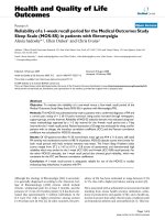
The figures in the left column in Figure 8 are plots of
the resulting force-displacement curves from three s ets
of data. First, it shows the experimental result s on the
curled and flat human finger postures during indenta-
tion. These data are from Little2 (Figure 8a), Ring2
(Figure 8b), and Middle2 (Figure 8c), which were chosen
as the representative parts of the human hand that the
experiments have shown to have high contact forces
during handshake interactions. Second, the figure shows
the indentation results on a finger phalanx of a prosthe-
tic hand. Third, the simulation results of the fing er pha-
lanx design with 2 mm inner pockets are overlaid on
the experimental results for comparison.
The figures in the right column in Figure 8 show the
magnitude of the displacements corresponding to the 1 N
force indentation. The results labelled with ‘curled’ and
‘flat’ in Figure 8 are from the experimental d ata taken
from the finger phalanges indentation of the 10 test sub-
jects. From the simulation results of the synthetic finger
phalanges, it can be observed from th e bars that having a
2 mm height internal p ocket can introduce significant
improvements in the skin compliance. Such results are
important particularly when they are compared a gainst
the skin compliance of the finger phalanges of a commer-
cially available prosthetic hand. The silicone material used
by the manufacturer of the prosthetic hand was stiff as
shown by the 0.2 mm deformation. Many prosthetic
hands are being sold for their cosmetic appearance and
durability. The development of pro sthetic hands for nat-
ural social touching interactions has not been the norm.
Conclusions
This paper addressed the c ontinuing need for improved
methods and designs that can make prosthetic hands
and arms unnoticed during social touching situations. In
addition to lifelike appearance, warmth and motion,
prosthetic skins that can replicate the natural softness of
thehumanhandmaybeabletoshieldtheuserfrom
social stigma. This could lead to the faster improvement
of his or her emotional well-being and permit the
resumption of a normal life (cf. [10,17,29]).
In this paper, the areas of the hand where typical con-
tact occurs during male-to-male handshakes were deter-
mined. The results show that the following areas of the
hand have contact forces greater than 2 N when grasped
during handshake: (a) the palm and the back of the
palm, (b) the thumb, (c) the proximal phalanx of the lit-
tle finger and the (e) middle phalanges of the little,
(f) ring, and (g) middle fingers. These are the areas that
envelope the handshaking partner’s hand for a full grasp.
Figure 7 Finite eleme nt simulation results showing the effects
of adding internal pockets to the synthetic skins (shown as
thick lines) and the effects of varying the layers (shown as thin
lines).
Cabibihan et al. Journal of NeuroEngineering and Rehabilitation 2011, 8:16
/>Page 8 of 11
The middle phalanges of the little, ring and middle
fingers were selected for indentations with a testing
machine. The force-displaceme nt curves were obtained
on both the flat hand position, which represents tapping
or caressing postures, and the curled-fingers position,
which represents handshake postures. The indentation
results show that the skin tissues at the finger phalanges
are compliant and are exhibiting large displacements
with minimal forces applied, i.e., a 1 N force corre-
sponds to skin tissue displacements of more than 2 mm.
The r esults also show that there are no significant dif-
ferences in the force-displacement data on flat-hand
position and curled-fingers position on the middle pha-
langes of the little, ring and middle fingers.
Figure 8 Comparisons of the finite element simulation results from the 2 mm inner pockets d esigns with the experimental results
from the phalanx of a prosthetic hand and the human finger phalanges of 10 subjects on (a) Little2, (b) Ring2, and (c) Middle2 at
1 N force indentation.
Cabibihan et al. Journal of NeuroEngineering and Rehabilitation 2011, 8:16
/>Page 9 of 11
Three-dimensional finite element models were presented
for investigating the effects of varying the internal topology
and varying the material layers in an attempt to duplicate
the skin compliance of human finger phalanges. The fol-
lowing conclusions can be made from the simulation
results. First, the skin compliance can be increased by
introducing open pockets on the internal structure of a
synthetic finger phalanx. Anarc-shapedpocketwitha
2 mm height on the internal structure increased the skin
compliance of the silicone material to as high as 235% and
the polyurethane material to 436%, as compared to a con-
figuration with a solid internal geometry.
Second, having one type of material for the 0.8 mm
external layer and another type for the internal layer
can affect the deflect ion of the finger phal anges’ surface,
but this combination has minimal effect when the top
layer of the pocket comes into contact with the base of
thefingerphalanx.Byknowingtheeffectsofhaving
multi-material layers, we can take advantage of a syn-
thetic skin design with a stiff external layer and a soft
internal layer. A stiff external layer can better protect
the tactile sensors and electronics that may be
embedded on the internal structure, while the soft inter-
nal layer can satisfy the requirements for more natural
social touching.
Lastly, the simulation results show that the synthetic
skins with the configurations described herein could
achieve lifelike skin compliance for light social touches,
especially under applied forces of about 1 N. T he inter-
nal pockets can significantly improve the compliance of
the synthetic skins that will be used for prosthetics.
Future studies can investigate other softer materials (i.e.
materials with lower Shore durometer values), find the
optimal thickness for the internal and external layers
and the internal pockets, and optimize the right combi-
nations of materials to be used as the internal and the
external layer.
Acknowledgements
This work was supported by the project ‘Design of Prosthetic Skins with
Humanlike Softness’ (R-263-000-506-133) funded by the Academic Research
Fund, Ministry of Education, Singapore. We thank Lifeforce Limbs and Rehab
Pte Ltd for the prosthetic hand sample.
Authors’ contributions
JJC designed the experiments, developed the simulations, performed the
data analysis and contributed to the drafting of the manuscript. RP
collected, processed and helped analyze the data. SSG participated in the
design of the study, analysis of the data and contributed to the drafting of
the manuscript. All authors have read and approved the manuscript. A
preliminary version of this paper was earlier presented at the International
Conference on Social Robotics at Incheon, Korea in 2009.
Competing interests
The authors declare that they have no competing interests.
Received: 17 June 2010 Accepted: 30 March 2011
Published: 30 March 2011
References
1. Hertenstein MJ, Keltner D, App B, Bulleit BA, Jaskolka AR: Touch
communicates distinct emotions. Emotion 2006, 6:528-533.
2. Kuiken TA, Dumanian GA, Lipschutz RD, Miller LA, Stubblefield KA: The use
of targeted muscle reinnervation for improved myoelectric prosthesis
control in a bilateral shoulder disarticulation amputee. Prosthetics and
Orthotics International 2004, 28:245-253.
3. Kuiken TA, Miller LA, Lipschutz RD, Lock BA, Stubblefield K, Marasco PD,
Zhou P, Dumanian GA: Targeted reinnervation for enhanced prosthetic
arm function in a woman with a proximal amputation: a case study.
Lancet 2007, 369:371-380.
4. Kuiken TA, Li G, Lock BA, RD L, Miller LA, Stubblefield KA, Englehart KB:
Targeted muscle reinnervation for real-time myoelectric control of
multifunction artificial arms. Journal of the American Medical Association
2009, 301:619-628.
5. The i-Limb Hand. [ />6. Friedman RM, Hester KD, Green BG, LaMotte RH: Magnitude estimation of
softness. Exp Brain Res 2008, 191(2):133-42.
7. Gallagher P, MacLachlan M: Adjustment to an artificial limb: A qualitative
perspective. Journal of Health Psychology 2001, 6:85-100.
8. Gallagher P, MacLachlan M: Development and psychometric evaluation of
the trinity amputation and prosthesis experience scales (TAPES).
Rehabilitation Psychology 2000, 45:130-154.
9. Rybarczyk B, Nicholas JJ, Nyenhuis DL: Coping with a leg amputation:
Integrating research and clinical practice. Rehabilitation Psychology 1997,
42:241-255.
10. Murray CD: The social meanings of prosthesis use. Journal of Health
Psychology 2005, 10:425-441.
11. Edin BB, Ascari L, Beccai L, Roccella S, Cabibihan JJ, Carrozza MC: Bio-
inspired sensorization of a biomechatronic robot hand for the grasp-
and-lift task. Brain Research Bulletin 2008, 75:785-795.
12. Matrone G, Cipriani C, Secco E, Magenes G, Carrozza M: Principal
components analysis based control of a multi-dof underactuated
prosthetic hand. Journal of NeuroEngineering and Rehabilitation 2010, 7:16.
13. Abboudi RL, Glass CA, Newby NA, Flint JA, Craelius W: A biomimetic
controller for a multifinger prosthesis. IEEE Transactions on Rehabilitation
Engineering 1999, 7:121-129.
14. Carrozza MC, Suppo C, Sebastiani F, Massa B, Vecchi F, Lazzarini R,
Cutkosky MR, Dario P: The SPRING hand: Development of a self-adaptive
prosthesis for restoring natural grasping. Autonomous Robots 2004,
16:125-141.
15. Castellini C, Fiorilla AE, Sandini G: Multi-subject/daily-life activity EMG-
based control of mechanical hands. Journal of NeuroEngineering and
Rehabilitation 2009, 6.
16.
Carrozza MC, Cappiello G, Micera S, Edin BB, Beccai L, Cipriani C: Design of
a cybernetic hand for perception and action. Biological Cybernetics 2006,
95:629-644.
17. Leow MEL, Pho RWH, Pereira BP: Esthetic prostheses in minor and major
upper limb amputations. Hand Clinics 2001, 17:489-497.
18. Livingskin. [ />19. Cabibihan JJ, Pattofatto S, Jomaa M, Benallal A, Carrozza MC: Towards
humanlike social touch for sociable robotics and prosthetics:
Comparisons on the compliance, conformance and hysteresis of
synthetic and human fingertip skins. International Journal of Social
Robotics 2009, 1:29-40.
20. Cabibihan JJ, Pradipta R, Chew YZ, Ge SS: Towards humanlike social touch
for prosthetics and sociable robotics: Handshake experiments and finger
phalange indentations. In Advances in Robotics. Volume 5744. Edited by:
Kim JH, Ge SS, Vadakkepat P, Jesse N. Springer; 2009:73-79, LNCS.
21. Cabibihan JJ, Ge SS: Towards humanlike social touch for prosthetics and
sociable robotics: Three-dimensional finite element simulations of
synthetic finger phalanges. In Advances in Robotics. Volume 5744. Edited
by: Kim JH, Ge SS, Vadakkepat P, Jesse N. Springer; 2009:80-86, LNCS.
22. Greenbaum PE, Rosenfeld HM: Varieties of touching in greetings:
Sequential structure and sex-related differences. Journal of Nonverbal
Behavior 1980, 5:13-25.
23. Chaplin WF, Phillips JB, Brown JD, Clanton NR, Stein JL: Handshaking,
gender, personality, and first impressions. Journal of Personality and Social
Psychology 2000, 79:110-117.
24. Beccai L, Roccella S, Ascari L, Valdastri P, Sieber A, Carrozza MC, Dario P:
Development and experimental analysis of a soft compliant tactile
Cabibihan et al. Journal of NeuroEngineering and Rehabilitation 2011, 8:16
/>Page 10 of 11
microsensor for anthropomorphic artificial hand. Mechatronics, IEEE/ASME
Transactions on 2008, 13:158-168.
25. Storakers B: On material representation and constitutive branching in
finite compressible elasticity. Journal of the Mechanics and Physics of Solids
1986, 34:125-145.
26. Wu JZ, Dong RG, Rakheja S, Schopper AW, Smutz WP: A structural
fingertip model for simulating of the biomechanics of tactile sensation.
Medical Engineering and Physics 2004, 26:165-175.
27. Tschoegl NW: The phenomenological theory of linear viscoelastic behavior: An
introduction New York: Springer-Verlag; 1989.
28. Dassault: Abaqus Theory Manual v.6.8-EF Providence, RI, USA: Dassault
Systemes Simulia Corp; 2008.
29. Pillet J, Didierjean-Pillet A: Aesthetic hand prosthesis: gadget or therapy?
Presentation of a new classification. The Journal of Hand Surgery 2001,
28:523-528.
doi:10.1186/1743-0003-8-16
Cite this article as: Cabibihan et al.: Prosthetic finger phalanges with
lifelike skin compliance for low-force social touching interactions.
Journal of NeuroEngineering and Rehabilitation 2011 8:16.
Submit your next manuscript to BioMed Central
and take full advantage of:
• Convenient online submission
• Thorough peer review
• No space constraints or color figure charges
• Immediate publication on acceptance
• Inclusion in PubMed, CAS, Scopus and Google Scholar
• Research which is freely available for redistribution
Submit your manuscript at
www.biomedcentral.com/submit
Cabibihan et al. Journal of NeuroEngineering and Rehabilitation 2011, 8:16
/>Page 11 of 11