báo cáo hóa học: "Performance adaptive training control strategy for recovering wrist movements in stroke patients: a preliminary, feasibility study" pptx
Bạn đang xem bản rút gọn của tài liệu. Xem và tải ngay bản đầy đủ của tài liệu tại đây (3.21 MB, 11 trang )
Journal of NeuroEngineering and Rehabilitation
Research
Performance adaptive training control strategy
for recovering wrist movements in stroke patients:
a preliminary, feasibility study
Lorenzo Masia*
1
,MauraCasadio
2
,PsicheGiannoni
3
,GiulioSandini
1,2
andPietroMorasso
2
Addresses:
1
Robotics Bra in and Cognitive Science Dept, Italian Institute of Technology (IIT), Genoa, Italy,
2
Dept of Informatics, Systems and
Telematics, University of Genova, Italy and
3
ART Rehabilitation and Educational Center srl, Genoa, Italy
E-mail: Lorenzo Masia* - lorenzo. ; Maura Casadio - ; Psiche Giannoni - psiche ;
Giulio Sandini - giulio.sandini@ iit.it; Pietro Morasso - pietro.m
*Corresponding author
Published: 7 December 2009 Received: 24 March 2009
Journal of NeuroEngineering and Rehabilitation 2009, 6:44 doi: 10. 1186/1743-0003-6-44
Accepte d: 7 December 2009
This article is available from: />© 2009 Masia et al; licensee BioMed Central Ltd.
This is an Open Acces s article distrib uted under the terms of the Creativ e Commons Attribution Licen se (
http:// creativecommons .org/licenses/by/2.0),
which permits unrestricted use, distribution, and reproduction in any medium, provided the original work is properly cited.
Abstract
Background: In the last two decades robot training in neuromotor rehabilitation was mainly
focused on shoulder-elbow movements. Few devices were designed and clinically tested for
training coordinated movements of the wrist, which are crucial for achieving even the basic level of
motor competence that is necessary for carrying out ADLs (activities of daily life). Moreover, most
systems of robot therapy use point-to-point reaching movements which tend to emphasize the
pathological tendency of stroke patients to break down go al-directed movements into a number of
jerky sub-movements. For this reason we designed a wrist robot with a range of motion
comparable to that of normal subjects and implemented a self-adapting training protocol for
tracking smoothly moving targets in order to facilitate the emergence of smoothness in the motor
control patterns and maximize the recovery of the normal RoM ( range of motion) of the different
DoFs (degrees of Freedom).
Methods: The IIT-wrist robot is a 3 DoFs light exoskeleton device, with direct-drive of each DoF
and a human-like range of motio n for Flexion/Extension (FE), Abduction/Adduction (AA) and
Pronation/Supination (PS). Subjects were asked to track a variable-frequency oscillating ta rget using
only one wrist DoF at time, in such a way to carry out a progressive splinting therapy. The RoM of
each DoF was angularly scanned in a staircase-like fashion, from the “easier” to the “more difficult”
angular position. An Adaptive Controll er evaluated online performance parameters and modulated
both the assistance and the difficulty of the task in order to facilitate smoother and more precise
motor command patterns.
Results: Three stroke subjects vol unteered to participate in a preliminary test session aimed at
verify the acceptability of the device and the feasibility of the designed protocol. All of them were
able to perform the required task. The wrist active RoM of motion was evaluated for each patient
at the beginning and at the end of the test therapy session and the results suggest a positive trend.
Conclusion: The positive outcomes of the preliminary tests motivate the planning of a clinical
trial and provide experimental evidence for defining appropriate inclusion/exclusion criteria.
Page 1 of 11
(page number not for citation purposes)
BioMed Central
Open Access
Background
Decreased wrist range of motion (ROM) (flexion and/or
extension, abduction/adduction or pronation/supina-
tion) after trauma or surgery can be a challenging
problem. Physica l therapy, orthoses, and additional
surgical interventions may not restore the desired
functionality even after an intensive rehabilitation pro-
gram. Therapists spend a considerable amount of practice
time in differential diagnosis of these losses and selecting
appropriate intervention strategies to res tore passive and
active motion in concordance with the pathology and to
prevent loss of range of motion after i njury.
While the regular treatment for wrist stiffness is physical
therapy or surgery, researchers are looking for an
alternative and more efficient and automatic procedure
by means of robotic applications.
Several systems for wrist rehabilitation have been
developed in research centres and universities, for
example RiceWrist [1]; MIME [2]; IMT3 [3], HWARD
[4]; the Okayama University pneumatic manipulator [5],
and the devices overviewed in [6-9]. The majority are
also used for rehabilitation in health centres and
hospitals, often coupled with MIT-MANUS [10],
ARMIN [11], MIME, HapticMaster [12] and wire-based
device from Rosati et al. [13] for rehabilitation of
proximal limb. Robot assisted therapy are primarily
based on goal-directed point-to-point movement invol-
ving multiple DoFs [14]; main purpose is increasing the
ROM of the paretic limb in order to regain motor
abilities for the Activities of Daily Living (ADL). Contra-
rily regular physical therapy of wrist rehabilitation
consists in a splinting treatment for each single DoF at
time, and there have been many studies that look at the
splints’ effectiveness and what type of splint would be
best [15,16]. Static progressive splinting is a time-
honored concept, for more than 20 years, clinicians
have rec ogn ized the effecti veness of static progressive
splints to improve passive range of motion (PROM).
Splint designers then sought a means to improve the
technique with components that offer infinitely adjus-
table joint torque control and are easy to apply,
lightweight, low-profile, and reasonably priced.
Dynamic splints use some additional component
(springs, wires, rubber bands) to mobilize contracted
joints [17 -19]. This dynamic pull functions to provide a
controlled gentle force to the soft tissue over long periods
of time, which encourages tissue remodeling without
tearing. The issues that make dynamic or static progressive
splinting tech nicall y diff icult i nclude determining how
much force to use, how to apply the force, how long to
apply the force, and how to prevent added injury to the
area. Things could change if the dynamic splinting is
delivered using devices which are able to modulate torque
delivering and space the range of motion.
Therefore we intend to approach the robotic therapy for
wrist rehabilitation using a continuous dynamic splint-
ing of each single DoF but contrarily to the regular
progressive splinting we want also to highlight the
voluntary component of movement. A performance
adaptive control strategy has been developed, with the
purpose of providing variable assistance by means of a
general training paradigm for stroke patients.
Methods
Apparatus: the wrist device
The Wrist-Robot [20], herewith reported, ha s been
developed at the It alian Institute of Technology with
three main requirements: 1) back-drivability of the 3
DoFs (Degree of Freedom), in order to assure a smooth
haptic interaction between the robot and the patient;
2) mechanical and electronic modularity, in order to
facilitate the future integration into a haptic bimanual
arm-wrist-hand system with up to 12 DoFs; 3) scalable
software architecture. The Wrist Robot is intended to
provide kinesthetic feedback during the training of
motor skills or rehabilitation of reaching movements.
Motivations for application of robot therapy in rehabi-
litation of neurological patients come from experimental
studies about the practice-induced plastic reorganization
of the brain in humans and animal models [21,22].
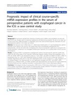
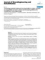
The robot (figure 1) is a 3 DOFs exoskeleton: F/E
(Flexion/Extension); Ad/Ab (Adduction/Abduction); P/S
(Pronation/Supina-tion).
The chosen class of mechanical solutions is based on a
serial structure, with direct drive by the motors: one
motor for pronation/supination, one motor for flexion/
extension and two parallel coupled motors for abduc-
tion/adduction that allow t o balance the pronosupina-
tion rotation during motion.
The problem of measurement of arm position is thus
reduced to the solution of the device kinematics, with no
further transformations required, allowing to actuate the
robot to control feedback to a specific human joint, for
example to constr ain the forearm rotation du ring wrist
rehabilitation, without affecting other joints.
The corresponding rotation axes meet at a single point as
shown in figure 1.
The subjects hold a handle connected to the robot and
their forearms are constr ained by velcros® to a rigid
holder in such a way that the biomechanical rotation axes
Journal of NeuroEngineering and Rehabilitation 2009, 6:44 />Page 2 of 11
(page number not for citation purposes)
are as close as possible to the robot ones. Unavoidable
small joints misalignments are partially reduced by
means of a sliding connection between the handle and
the robot and the forearm can be moved vertically in
order to fit the rotation axis of the pronation/supination
DoF. In order to minimize the effect of occasional
compensatory shoulder/trunk movements during train-
ing exercises, the body is firmly strapped to a robust chair
andthechairispositionedinsuchawaytohavethe
elbow flex ed abou t 90 deg and the hand point ing to the
centre of a 21” CD screen, in correspondence with the
neutral anatomical orientation of the hand.
Having in mind the general requirements of robot
therapy [22,23], we identified the following design
specifications:
1. sufficient level of the torque at the handle (tab. I)
2. large workspace
low friction and direct drive motors enhance the back-
driveability of the manipulandum, thus simplifying its
control without needing a closed loop force control
scheme. The mechanical range of motion (ROM) is as
follows: F/E =-70°↔ +70°; Ad/Ab =-35°↔ +35°; P/S =
-80° ↔ +80°. These values approximately match the
ROM of a typical human subject (Table 1).
Each DOF is measured by m eans of a high-re solution
encoder (2048 bits/rev) and is actuat ed by one or two
brushless motors, in a direct-drive, back-drivable con-
nection, providing the continuous torque values
reported in table 1. The control architecture integrates
the wrist controller with a bi-dimensi ona l visual virtual
reality environment ( VR) for showing to the subjects the
actual joint rotation transformation of the hand, the
corresponding target direction and two performance
indicators defined in the following. The software
environment is based on Simulink® and RT-Lab®. The
control architecture includes three nested control loops:
1) an inner loop, running at 7 kHz, used by the motor
servos; 2) an intermediate loop, running at 1 kHz, for the
low level control; 3) a slower loop, running at 100 Hz,
for implementing the VR environment and the user
Figure 1
3DoF Wrist Device. It has 3 DOFs: F/E, P/S, Ad/Ab. One motor is used for F/E and P/S; two motors for Ad/Ab.
Table 1: ROM of the Robot and the Human wrist
Wrist
Joint
Human joint
range of
motion [deg]
Wrist Device
Workspace
Capability [deg]
Human
Isometric
Torque [Nm]
Wrist Device
Continuous
torque [Nm]
Supination/Pronation 86/71 80/80 5.2 7.1
Fle xion/Exte nsion 73/71 70/70 19.8 12.4
Abduction/Adduction 33/19 35/35 20.8 12.9
comparison between range of motion and joint torque of a human [24-26] and the IIT-wrist device; the values of the continuous delivered t orque are
obtained by a design compromise between backdrivability and power requirements based on anthropometric data.
Journal of NeuroEngineering and Rehabilitation 2009, 6:44 />Page 3 of 11
(page number not for citation purposes)
interface. The mechanical structure of the wrist robot was
designed in such a way to allow a simple and immediate
mounting for patients’ forearm.
Task
The task is mono-dimensional tracking of a sinusoidally
moving target, using one DOF at a time: F/E, Ad/Ab or
P/S, respectively; this approach is consistent with the
dynamic splinting paradigm which is primarily used to
regain the passive ROM after trauma or surgical
intervention; the subject aims to move the handle to
track the harmonic motion of the target using his/her
active ROM; the robot gently intervenes if the subject is
not able to actively cover the required angular displace-
ment. Three different experiments were then carried out
for the three different DoFs of the wrist. For each
experiment, t here was one active DoF, which received
controlled assistance by the robot, while the two other
DoFs were hold by the robot in a small n eighbourhood
of the neutral position [24-26].
In order to make the task interesting and challenging at
the same t ime, the level of difficulty was managed by the
controller modulating two parameters as a function of
the performance: a) frequency of the target motion; b)
level of the robot assistance. The controller implementa-
tion is discussed and illustrated in the next section.
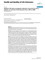
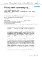
Controller architecture
The general control architecture consists of three blocks:
1) target motion generator; 2) force filed generator;
3) performance evaluator.
Figure 2 shows (on the left) the control scheme named
“Target Motion generator” and exemplifies a segment of
the oscillatory pattern that span the entire ROM in a
progressive manner. The
Target Motion Generator is
characterized by the following set of e quations that are
sampled at 1 kHz by the inner control loop and they will
be explained in present section.
Here #
W
stands for the joint angular rotation of anyone
of the three DoFs of the robot: F/E, Ab/Ad, P/S (figure 2).
In particular, #
T
is the time-varying target angular
position, characterized by an harmonic motion with
frequency f, amplitude A, and bias or offset #
o
(eq. 1).
ϑϑ π
To
Aft=+⋅sin 2
(1)
The bias is moved in a staircase manner (eq. 2), in order
to progressively span the whole ROM of each DoF (#
min
↔ #
max
)bymeansofns steps (ns =11inour
experiments).
ϑϑϑ
o
staircase ns= (, ,)
min max
(2)
Figure 2
Controller diagram.The“assist-as-needed” force parabolic term continuously inputs tor que τ
m
when errors are present
during the tracking task. The input torque to the robot/hand system is t he sum of different contributions of a viscous field τ
v
,
agravityτ
G
and inertia τ
I
compensation. τ
H
is the torque applied by the subjects wrist.
Journal of NeuroEngineering and Rehabilitation 2009, 6:44 />Page 4 of 11
(page number not for citation purposes)
Each step of the staircase has a duration of 40s plus a 4s
rest interval, during which the harmonic motion of the
target is stopped as well as the attractive force. For each
DoF, the ROM is scanned by the staircase starting from
the “easier” to the “more difficult ” angular position,
taking into account the specific pathological conditions
of the treated subjects. In this feasibility study the
sequence was, for all the patients, from Flexion to
Extension, from Adduction to Abduction, and from
Pronation to Supination, respectively. The sequence is
ordered “from easy to difficult” considering the hyper-
tonic trend in the range of motion for each trained DoF:
1) the offset angle steps from the easy (more natural and
less hypertonic) to the difficult (less natural) joint
configuration; 2) the oscillation is modulated from
slow (easy) to quick (difficult) frequency.
Table 2 shows t he amplitude of the target oscillations
and the range of values of the angular offset/bias: such
range is divided into 11 part s corresponding to the s teps
of the staircase. Therefore each step amplitude is
different for the different three spaced ROMs. Thus, the
subjects are progressively trained in a limited workspace
but the gradual change of the offset angle allows them to
experience the whole ROM for each single DoF (as a
progressive splinting). The initial position was chosen
taking into consideration the specific pathological
conditions;i.e.subjectstraineachDofstartingform
the less hypertonic portion of each ROM to gradually
space the whole workspace.
Eq. 3 identifies the tracking error for each time instant
(#
w
is the current angular position o f the wrist DoF)
which is input in the “Force Fiel d Generator” and the
“Performance Evaluator”.
e
TW
=−
ϑϑ
(3)
The assistive torque provided by the motor is computed
in the “Force Field Generator” according to eq. 4 and then
transformed into the corresponding current drive.
τττττ
WmGIv
=++−
(4)
The actual delivered torque τ
w
is the sum of different
control ef forts that consider assistance τ
m
(eq. 5), gravity
compensation τ
G
(eq. 6), inertia compensation τ
r
(eq. 7)
and a viscous field τ
v
(eq. 8) in order to stabilize by a
damping effect the unwanted oscillation at the end
effector.
τ
m
Ke sign e=
2
()
(5)
τϑ
G
G= ()
(6)
τϑϑ
IWW
Is= ()
2
(7)
τϑ
vW
Bs=
(8)
The different contribution of the force field generator is
shown in figure 2 (right).
The assistive control law τ
m
consists of a non linear
elastic field with a parabolic profile ( eq. 5). This non
linear characteristic was chosen according to the princi-
ple of minimal assistance [27] or also assist as needed [28]:
assistance forces/torques should be kept as low as
possible in o rder to promote the emergence of voluntary
control. In fact, the c hos en pattern of assistance has a
less-than-linear increase for small errors, thus facilitating
the emergence of active un-aided control at the end of
training; for large errors, which are likely to occur at the
beginning of training, the assistance grows more than
linearly in order to speed up the learning process. The
same concept of minimal assistance is used for selecting,
in an individual-specific manner, the gain K:itischosen
as the minimum value capable to induce the initiation of
movements of the paretic wrist and it was chosen by
experimentally observing the active voluntary move-
ments of the participating subjects before starting the
rehabilitation protocol.
The “Performance Evaluator” computes intermittently the
average angular error given by eq. 3 in a time window
(T
e
=2s):
F
T
e
tt ttdt
eTW
T
e
=−−−
∫
1
0
ϑϑ
() ()
(9)
where
ˆ
t
is the time instant at which the current
oscillation terminates or also the zero-crossing of the
#
T
-#
W
waveform.
The “Performance Evaluator” modulates the “difficulty” of
the tracking task, i.e. the oscillation frequency f =1/ΔT,
by changing it in a smooth way at the end of each
Table 2: Growth and decay coeffici ents of Eq. 9 for each DOF and
amplitude oscillation and max/min ROM for each Dof
Joint a [Hz] b [Hz
2
/rad] A [deg] #
min
[deg] #
max
[deg]
FE 0.2 0.0012 11.5 -14.5 14.5
AA 0.2 0.0015 11.5 -14.5 14.5
PS 0.25 0.0008 14.5 -30.5 30.5
The table provides the growth (a) and decay coefficient (b)usedbythe
performance evaluator block of the controller to change the frequency
of oscillat ion of the target. For each DOF, the table stores the amplitude
(A) of the target oscillations while #
min
, #
max
are the minim um and
maximum value assumed by the angular offset #
o
to space the range of
motion of each Dof.
Journal of NeuroEngineering and Rehabilitation 2009, 6:44 />Page 5 of 11
(page number not for citation purposes)
complete oscillation cycle according to the following
equation:
ΔΔffFT
e
=⋅−⋅
[]
⋅
αβ
(10)
The equation contains two terms: a raising term with a
coefficient a and a decaying term depending on the
average angular error F
e
multiplied by the decay
coefficient b. For clarity sake figure 2 shown the entire
controller scheme highlighting the different blocks of the
controller. There are also two saturation levels that keep
the task in a suitable range of difficulty: we chose the
range 0.1-1.0 Hz empirically, looking at the performance
of the unimpaired subjects. Also the values of a and b for
each DoF were experimentally chosen, in order to
balance the conflicting requirements of readiness and
smoothness and provide a s ymmetric counterbalance of
decaying and raising contributions: these values are
listed in table 2.
During the performance of an e xercise, when eq. 2
switches the o ffset #
o
from one step to the next one, the
initial value of eq. 10 is reset to the minimum value of
frequency (0.1 Hz). Therefore, the initial target oscilla-
tion will be very slow and will smoothly speed-up as a
function of the tracking accuracy e = #
T
- #
W
,untilthe
end of the step (40s).
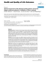
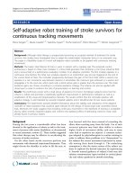
Virtual Reality environment
TheVRprocessdisplaysonthescreenthetrajectoryof
the target and the wrist angular position (figure 3). The
target and the wrist positions are represented graphically
as ‘pleasant’ images: a dolphin chasing a ball or a squirrel
hunting an acorn. The target path on the P C screen is
horizontal in the F/E experi ment, vertical in the Ab/Ad
experiment, and a circular segment in the P/S experi-
ment.
We wante d to strengthen the effectiveness of the system
in monitoring wrist use while providing encouragement
and reminders throughout a therapy session [29].
Hencewealsodisplay,ontheleftsideofthescreen,the
instantaneous levels of the two performance indicators
by means of height-modulated bars: 1) the level of
assistance and 2) the frequency of osci llation. The
patients were instructed to minimize the height of the
former one while maximizing the height of the latte r.
This kind of intuitive performance feedback was easily
understood by the patients and well appreciated by
them.
Subjects
Three stroke subjects volunteered to participate in this
preliminary study. The recruitment was among t he
Figure 3
Virtual reality environment in the therapy session. A) Experimental set-up in the P/S case: the dolphin chasing the ball.
The two bars on the left of the screen disp lay two per formance indicators. B) F/E excercise; D) Ab/Ad excercise;
D) P/S exercise.
Journal of NeuroEngineering and Rehabilitation 2009, 6:44 />Page 6 of 11
(page number not for citation purposes)
outpatients of the ART Rehabilitation and Educational
Centre (Genoa, Italy), and based the following inclusion
criteria: 1) diagnosis of a single, unilateral stroke verified
by brain imaging; 2) suffic ient cognitive and languag e
abilities to understand an d follow instructions; 3)
chronic condition (at least 1 year after stroke). Table 3
summarizes the anagraphic data (age, sex) and the
clini cal state (eti ology, disease duration, affected side,
Fugl Meyer and Ashworth scores) collected at the ART
Rehabilitation and Educational Centre (Genoa, Italy).
The research conforms to the ethical standards laid down
in the 1964 Declaration of Helsinki, which protects
research subjects. Each subject signed a consent form
that conforms to these guidelines. The robot training
sessions were carried out at the Human Behaviour Lab of
IIT (Genoa, Italy), under the supervision of an experi-
enced phy siotherapist of the ART Rehabilitation and
Educational Center.
Collected Data
The following parameters were estimated for each DoF:
- Max frequency: the maximal frequency that the subject
is able to reach, in the possible range 0.1-1 Hz;
- Mean assistive torque: the average torque delivered to
the patient during the rehabilitation protocol for each
DoF;
- ROM achieved in the single step;
- Mean speed.
Moreover we estimated:
- The ROM in the whole session (minim um-maximum
degree of movement in theentireexercise);
- The active voluntary ROM of the subject holding the
passive inactivated device, before and after the exercise in
order to compare if the rehabilitation protocol w ould
provide fast benefits e ven after one therapy session.
Results
Although the clinical states of the three subjects are
rather different, a s reported in table 3, all of them were
able to carry out the proposed exercises in a consistent
way, with different performance profiles considering the
performance adaptive nature of the controller architec-
ture. For clarity sake, in the present preliminary/
feasibility study, the following figures will refer to
subject S3, who is the most severely affected and
therefore the worst case in the experienced population.
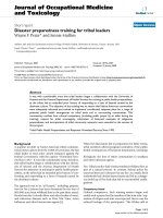
Figure 4 shows the evolution of the frequency of the
moving target for each DoF, while the #
o
position scans
through the 11 values that are uniformly placed in the
corresponding ROM: 40s for each step + 4s of rest
between one step and the next one. For each step, the
peak value of the frequency depends on the position in
the workspace of each DoF and on the specific
pathological condition of each patient: the figure
shows that S3 has higher difficulty in extension than
flexion, in adduction than abduction, and in pronation
than supination.
Table 3: Patients demographics
ID Age Sex DD Eti PH FM Ash
S1 37 F 5 I R 25 1+
S2 57 F 3 H L 36 1
S3 60 M 6 H L 22 3
Age & DD (disease duration): years; Eti (etiology): Ischemic/Hemor-
rhagic; FM: Fugl-Meyer score (arm section 0-66); Ash: Ashworth score
(0-4). PH: paretic hand (Right/Left).
Figure 4
Course of the target frequency when the offset
position steps through the ROM. At the beginning of
each step the frequency is reset to its minimum value
(0.1 Hz); the maximum possible value is 1 Hz. Subject S3.
Journal of NeuroEngineering and Rehabilitation 2009, 6:44 />Page 7 of 11
(page number not for citation purposes)
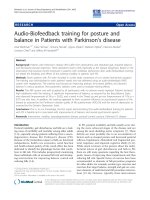
Figure 5A summarizes the trend of the peak frequency at
the different steps comparing it with the corresponding
evolution of the assistive torque provided by the robot. It
appears that t he two se ts of curves provide compatible
and complementary messages as regards the overall
performance of S3: he reaches peak frequency at about
full flexion and mid-range of abduction/adduction and
prono/supination; in the same areas the assistance
torque reaches local minima, highlighting the fact that
higher performance is obtained when a higher capability
of voluntary motio n is pre sent ne ed ing a lowe r leve l of
assistance.
The information provided by figures 4 and 5A is
complemented by t he measurement of the Active ROM
(voluntary capability of moving) for each type of
movement of the wrist DoFs. These measurement s were
carri ed out at the beginning and at the end of th e
training session, by using the same wrist robot in order
to normalize the in trins ic constraints (biomechanical
and neurological) as well as the constraints determined
by the robot. In the measurement, only one DoF at a
time was allowed to move freely (with no assistive
control applied), while the two remaining DoF were
hold by the robot in the approximated neutral positions.
Table 4 summarizes t he measurements before starting
the protocol. Shaded cells correspond to the more
impaired movements for each subject: 1) all of them
lack mobility in Extension rather than Flexion; 2) S1 has
a higher deficiency in Abduction that in Adduction,
Figure 5
complementary analysis between assistive torque and maximum frequency reached during tracking (subject
S3). (A) Left panel: Maximal target fr equency reached for the different DOFs during the 40 s steps, identified by the starting
position in the ROM with r espect to the ne utral position. Right panel: Mean value of th e assistive torque (in 10-3 Nm) du ring
the corresponding steps. (B) Mean tracking speed, for the different DOFs, in the different 40s steps, identified by the starting
position in the ROM with respect to the neutral position. Gray and black curves correspond to the opposing parts of the
movements (F vs. E, Ad vs. A b, P vs. S). (C) For each value of the offset rotation and each DOF, the graphs show the ROM of
the robot (shaded ban d) and the ROM of subject S3 (black curves). X-axis identified the spammed ROM for the exercised Dof;
positive and negative value are referred respectively to F/E, Ab/Ad and P/S while zero is the neutral position. Y-axis is the
amplitude oscillation reached by the target (shaded band) and by the subject.
Journal of NeuroEngineering and Rehabilitation 2009, 6:44 />Page 8 of 11
(page number not for citation purposes)
while S2 and S3 have the opposite impairment; 3) S1
shows a higher deficit in Supinat ion whereas S2 and S3
are worse in Pronation.
A similar kind of pattern, i.e. asymmetry of performance
for easier vs. more difficult movement directions, can be
shown as regards the maximal values of frequency
reached by the target (table 5).
We can also observe that minima l frequen cy values
correspond to the position in which subjects have a
reduced range of motion. Moreover , table 5 shows t hat
maximal assistive joint torque is generally provided on
thesideofthemovementofeachDoFwherethesubject
is more defective.
The performance of the subjects can also be investigated
by comparin g the mean speed of the two opposite
movementsforeachDoFinrelationwitheachoffsetstep
of the staircase (Figure 5B: F vs. E, Ad vs. Ab, and P vs. S).
We can observe that, for each DoF, the speed curves for
the opposing rotations are quite similar in spite of the
fact that there is a significant asymmetry in the ROM, as
shown in tables 4 before and a fter threatment. This
suggests that the training protocol is effective in two
main ways, by inducing at the same time the patient to
behave in a more functional and physiological way:
1) exercising movements that are more diff icul t for
him/her, given his specific pathological condition,
for example Extension vs. Flexion;
2) moderating the predominance of pathology-aided
behaviours that would enhance Flexion vs. Extension
etc.
At last, figure 5C compares, for each DoF, the ROM of
the robot target motions (shaded grey band is the
amplitude of the target oscillation at different starting
position on e ach DoF workspace) with the act ual ROM
(bold lines with markers for the two directions of each
Dof) exhibited by patient S3 in relation with each offset
position. It a ppears that generally the maximal joint
rotation achieved by the patient is asymmetric in the two
opposing directions of each DoF (P vs S, F vs. E, Ad vs.
Ab) and this is reflected in the pattern of values stored in
table 4 of the active range of motion measured by the
uncontrolled device at the beginning of protocol. i.e. In
spite of the assistance, the subject S3 does not succeed in
following t he harmonic motion of the target represented
by the shaded grey band; he systematically undershoots
extension (blue line) and overshoots flexion (red line),
whereas the performance is closer to physiological
conditions for the two other DoFs.
On the other hand, table 4 reports the active range of
motion (uncontrolled device) measured at the end of the
training session and the comparison between the part of
the table 4 shows a clear increase and symmetrisation
before and after the threatment; this result suggests that
using robot to generate mobilising splints might be
useful to modify the joint stiffness, and reducing
hypetonia; even if the t otal ROM is r educed the
symmetry notic eably increase s; it is possible the passiv e
component due to hyper tonicity before the splinting
added a bias to each joint drifting from the anatomical
neutral position.
In the lights of these considerations however we present
a preliminary study on the feasibility of using a
performance adaptive control strategy combined with a
Table 4: Active Range of motion of the subjects pre and post
treatment
PRE-TREATMENT
ID F
[deg]
E
[deg]
AD
[deg]
AB
[deg]
P
[deg]
S
[deg]
S1 60 7.5 12.2 3.0 6.0 3.8
S2 61.5 3.1 23.0 21.7 12.5 23
S3 59.5 -8.4 10.5 28.4 6.0 21.5
POST-TREATMENT
ID F
[deg]
E
[deg]
AD
[deg]
AB
[deg]
P
[deg]
S
[deg]
S1 25.67 19.23 18.62 15.68 38.90 37.41
S2 28.49 19.15 16.01 22.33 37.59 36.91
S3 27.38 15.70 18.24 19.22 34.88 36.67
(A) Active voluntary range of motion measured using the uncontrolled
(not active) devi ce before treatment. Grey cells correspond to the
more difficult movements for the subjects. (B) Reached ROM evaluated
during treatment. Bold data correspond to the more impaired
movements for the subjects considering each pathological condition.
Table 5: Maximal frequency reached and average assistive torque
MAXIMAL FREQUENCY REACHED
ID F
[Hz]
E
[Hz]
AD
[Hz]
AB
[Hz]
P
[Hz]
S
[Hz]
S1 0.45 0.35 0.51 0.38 0.75 0.57
S2 0.59 0.37 0.31 0.53 0.52 0.71
S3 0.44 0.28 0.28 0.45 0.48 0.66
AVERAGE ASSISTIVE TORQUE
ID F [mNm] E
[mNm]
AD
[mNm]
AB
[mNm]
P
[mNm]
S
[mNm]
S1 12 11 9 16 15 27
S2 12 12 8 6 26 19
S3 15 32 15 16 32 20
Maximum value of frequency oscillation reached by the subjects for
each type of exercised Dof direction during robot training. Average
assistive torque required by each subject for the extreme values of each
type of motion (e.g. maximum Flexion, etc.). Bold numbers cells indicate
more impaired movem ents.
Journal of NeuroEngineering and Rehabilitation 2009, 6:44 />Page 9 of 11
(page number not for citation purposes)
dynamic splinting; in order to strengthen the effective-
ness of the proposed approach a wider clinical protocol
with higher number of subjects and therapy se ssion is
needed.
Discussion
Although it has been shown i n a number of studies that
robots can decrease motor impairment after stroke with
certain advantages, less emphasis to date has been put on
robotic developments for the hand and on correspo nd-
ing preliminary clinical studies. A notable exception is
the work by Takahashi et al. [4] who reported t he use of
the pneumatic-actuated HWARD wrist r obot with 13
patients. The main difference of HWARD with respect to
the Wrist robot ( here with reported) is related to the
wrist movements: HWARD can only operate with F/E
whereas Wrist Robot can operate equally well with Ab/
Ad and P/S.
In this preliminary experiment investigating patients,
only one joint DoF was exercised at a time. The
procedure simulated as much as possible the use of
splints widely used in clinical applications. However,
there is no hardware or software limitation to design 2D
and 3D experiments, which indeed are planned and will
be carried out in the near future.
We wish to emphasize that our control system is based
of a principle of minimal assistance that focuses on the
initiation of the movement; on the contrary most of the
other rehabilitation robots, focuses on the termination
phase (goal directed movements), by forcing the patient
to complete the movements if he/she is unable to
achieve the target. We also plan to integrate in the robot
an active finger F/E unit, by means of a motorized
handle [30] to s tudy the impact of single-DoF rehabilita-
tion protocol on cylindrical grasping and compare the
effectiveness of different rehabilitation strategies that
include distal and/or proximal limb.
The results reported in this single-sessio n study show
that the proposed adaptive control strategy is robust, in
terms of patient response, is well accepted by the subjects
and the control architecture is capable to smoothly adapt
to the specific impairments of the patients without
needing a fine customization of the controller gains for
each subject; this controller robustness allows to
introduce the system in the clinical application provid-
ing a user friendly interface for users and patients, and to
deliver an automatic execution of the therapy sessions.
Conclusion
The result s of the presented preliminary work shows that
robotic therapy may improve motivations in patients
and provide tangible results even in a short term
experience. The technological approach with the use of
customized devices may strengthen the potentials of the
regular physical therapy in delivering assistance and
training. The proposed controller strategy is simply
basedonanautomationofthewellestablished
methodology of dynamic splinting; this kind of
approach can result familiar to the medical staff allowing
technology to progressively take part to the emerging
and increasing needs of rehabilitation, without shocking
the entrenched application of regular therapy. It remains
to be investigated, as we plan to do in a systematic
clini cal tria l, to wh ich extent a suitable protocol can
induce permanent improvements in the neural control
of wrist movements, necessary for any attempt to achieve
functional gains in the activities of daily life.
Competing interests
The authors have not competing interests as defined by
the BioMed Central Publishing Group, or other interests
that may influence re sults and discussion reported in this
study.
Authors’ contributions
LM conceived and designed the d evice used in the
present work. LM and MC carried out the experiments
and the data analysis and drafted the manuscript; PM
participated in the design of the study and carried out
the experiment; PG participated in the coordination of
the study and conceived the rehabilitation protocol,
assisting the patients during the robot therapy sessions;
GS conceived of the study, and participated in its design
and coordination.
All authors read and approved the final manuscript.
Acknowledgements
Acknowledgements: these work was carried out at Human Behaviour
Laboratory of Italian Institute of Technology and it was supported by a
gra nt of Italian Ministry of Scientific Research and Minist ry of Economy.
This work is partly supported by the EU grants FP7-ICT-271724
HUMOUR and FP7-ICT-2007-3 VIACTORS.
References
1. Gupta A, O’Malley MK, Patoglu V and Burgar C: Design, Co ntrol
and Performance of RiceWist: A Force Feedback Exoskele-
ton for Wri st Rehabilitation and Tr aining. The Intl J of Robotics
Res 2008, 27(1):233–251.
2. Shor PC, Lum PS, Burg ar CG, Loos Van der HFM, Majmundar M and
Yap R: The Effect of Robotic-Aided Therapy on Upper
Extremity Joint Passive Range of Motion Pain, Proc of Intl
Conf on Rehab Robot ics, Integration of Assisted Tech nol in
the Info rmation Age.IOS Press: Mounir Mokhtari 2001, 79–83.
3. Krebs HI, Volpe BT, Williams D, Celestino J, Charles SK, Lynch D
and Hogan N: Robot-Aided Reh abilitation: A Robot for Wrist
Rehabilitation. IEEE Trans on Neural Syst ems and Rehab Engineering
2007, 5:32 7–335.
4. Takahashi CD, Der-Ye ghiaian L, Le V, Motiwala RR and Cramer SC:
Robot-Based Hand Motor Therapy After Stokes. Brain 2008,
131:425–437.
Journal of NeuroEngineering and Rehabilitation 2009, 6:44 />Page 10 of 11
(page number not for citation purposes)
5. Takaiwa M and Noritsugu T: Development of Wrist Rehabilita-
tion Equipment Using Pneumatic Parallel Manipulator.
Proceeding of the 2005 IEEE International Conference o f Robotics and
Automation, Barcelona 2005, 2302–2307.
6. L ambercy O, Dovat L, Gassert R, Burde t E, Teo CL and Milner TE: A
Haptic Knob for Rehabilitation of Hand Function . IEEE
Transactions on Neural Systems and Rehabilitation Engineering (TN SRE)
2007, 15(3):356–366.
7. Hesse S, Schulte-Tigges G, Konrad M, Bardeleben A and Werner C:
Robot-assisted arm trainer for the passive and active
practice of bilateral forearm and wrist movements in
hemiparetic subjects. Arch Phys Med Rehabil 2003, 84(6):915–20.
8. L oureiro RCV, Collin CF and Harwin WS: Robot Aided Therapy:
Challenges Ahead for Upper Limb Stoke Rehabilitation.
Proceed of Intl Conf on Disability, Virtual Reality and Assoc Tech 2004,
33–39.
9. Jack D, Boian R, Merians AS, Tremaine M, Burde a GC, Adamovich S,
Recce M and Poizner H: Virtual Reality-Enhanced Stroke
Rehabilitation. IE EE Trans on Neural Syst and Rehab Engineer
2001, 9:30 8–318.
10. Krebs HI, Ferraro M, Buerger SP, Newbery MJ, Makiyama A,
Sandmann M, Lynch D, Volpe BT and Hogan N: Rehabilitation
robotics: pilot trial of a spatial extension for MIT-Manus.
Journal of NeuroEngineering and Rehabilitation 2004, 1:5.
11. Nef T, Mihelj M, Kiefer G, Perndl C, Muller R and Riener R: ARMin -
Exoskeleton for Arm Therapy in Stroke Patients. Proceedings
of the IEEE 10th International Conference on Rehabilitation Robotics, 13-
15 June 2007, Noordwijk, The Netherlands, 68–74.
12. Loureiro R and Harwin W: Reach & Gr asp therap y: Design and
control of a 9 DoF Robotic neuro-rehabilitation system. IEEE
10th Int Conf Rehab Robot., 13-15 June 2007, Noordwijk, The
Netherlands 2007, 68–74.
13. Rosati G, Gallina P and Masiero S : Design, Implementat ion and
Clinical Tests of a Wire-Based Robot for Neurorehabilita-
tion. IEEE Transactions on Neural Systems and Rehabilitation Engineer-
ing 2007, 15(4):560–569.
14. Timmermans AAA, Seelen HAM, Willmann RD and Kingma H:
Technology-assisted training of arm-hand skills in stroke:
concepts on reacquis ition of motor control and therapist
guidelines for rehabil itation technology design. Journal of
NeuroEngineering and Rehabilitation 2009, 6:1.
15. McG rath M, Ulrich S, Bonutti P, Smith J, Seyler T and Mont M:
Evaluation of Static Progressive Stretch for t he Treatmen t
of Wrist Stiffness. The Journal of Hand Surgery 2008, 33
(9):1498–1504.
16. Doo rnberg JN, Ring D and Jupiter JB: Static progressive splinting
for posttraumatic elbow stiffness. J Orthop Trauma 2006,
20:400–404.
17. McPherson JJ and Becker AH: Dynamic Splint to Reduce the
Passive Component of Hypertonicity. Archive s of Physical
Medicine and Rehabilitation 1985, 66:249–252.
18. Scheker LR, Chesher SP, Netscher DT, Julliard KN and O’neill WL:
Functional Results of Dynamic Splinting after Transmeta-
carpal, Wrist, and Distal Forearm Replan tation. Journal of
Hand Surgery 1995, 20:58 4–590.
19. Cov erda le J: Does a Uni-direc tional Dynamic Splint Affect Bi-
directional Wrist ROM? American Society of Hand Therapists
Annual Meeting, September 21, 2002.
20. Mas ia L, Casadio M, Morass o P, Pozz o T and Sandini G: Using a
Wrist Robot for Evaluating how Human Operators learn to
perform Pointing Movements to a Rotating Frame of
Reference. Proceed IEEE BioRob October 19-22 2008, Scottsdale,
AZ, USA 2008.
21. Nudo RJ: Mechanisms for recovery of motor fu nction
following cortical damage. Current Opinion in Neurobiology 2006,
16:638–644.
22. Tna H, Srinivan B, Eberman B and Che ng B: Human factors for the
design of a force refl ecting haptic int erface. Dynamic Syst
Control 1994, 55(1):353– 359.
23. Wolbrecht ET, Chan V, Rei nkensmeyer DJ and Bobrow JE:
Optimizing Compliant, Model-Based Robotic Assistance to
Promote Neurorehabilitation. IEEE Trans Neural Syst Rehabil
Engineer 2008, 16:286–97.
24. Basics of wrist rehabilitation protocols.
.
nasa.gov/education/protocols/basicwristelbow.php.
25. Bridger Robert: Introduction to Ergonomics. CRC 32008.
26. Gavriel Salvendy: Handbook of Human Factors and Ergo -
nomics.J Wiley; Third1997.
27. Casadio M, Giannoni P, Morasso P and Sanguineti V: A proof of
concept study for the integration of robot therapy with
physiotherapy in the treatment of stroke patients. Clinical
Rehab 2009, 23:217–228.
28. Emken JL, Benitez R, Sideris A, Bobrow JE and Reinkensmeyer DJ:
Motor adaptation as a greedy optimization of error and
effort. JNeurophysiol2007, 97(5):3997–4006.
29. Colombo R, Pisano F, Mazzone A , Delconte C, Micera S,
Carrozza MC, Dario P and Minuco G: Design strategies to
imp rove patient motivation during robot- aided rehabi lita-
tion. Journal of NeuroEngineering and Rehabilitation 2007, 4:3.
30. Masia L, Krebs HI, Capp a P and Hogan N: Design and
characterization of hand modul e for whole-arm reha bilita-
tion following stroke. IEEE/ASME Trans Mechatronics 2007,
12(4):399–407.
Publish with BioMed Central and every
scientist can read your work free of charge
"BioMed Central will be the most significant development for
disseminating the results of biomedical research in our lifetime."
Sir Paul Nurse, Cancer Research UK
Your research papers will be:
available free of charge to the entire biomedical community
peer reviewed and published immediately upon acceptance
cited in PubMed and archived on PubMed Central
yours — you keep the copyright
Submit your manuscript here:
/>BioMedcentral
Journal of NeuroEngineering and Rehabilitation 2009, 6:44 />Page 11 of 11
(page number not for citation purposes)