báo cáo hóa học: "Introducing a feedback training system for guided home rehabilitation" potx
Bạn đang xem bản rút gọn của tài liệu. Xem và tải ngay bản đầy đủ của tài liệu tại đây (1.24 MB, 11 trang )
MET H O D O LO G Y Open Access
Introducing a feedback training system for
guided home rehabilitation
Fabian Kohler
*
, Thomas Schmitz-Rode, Catherine Disselhorst-Klug
Abstract
As the number of people requiring orthopaedic intervention is growing, individualized physiotherapeutic rehabilita-
tion and adequate postoperative care becomes increasingly relevant. The chances of improvement in the patients
condition is directly related to the performance and consistency of the physiotherapeutic exercise s.
In this paper a smart, cost-effective and easy to use Feedback Training System for home rehabilitation based on
standard resistive elements is introduced. This ensures high accuracy of the exercises performed and offers gui-
dance and control to the patient by offering direct feedback about the performance of the movements.
46 patients were recruited and performed standard physiotherapeutic training to evaluate the system. The results
show a significant increase in the patient’s ability to reproduce even simple physiotherapeutic exercises when
being supported by the Feedback Training System. Thus physiotherapeutic training can be extended into the
home environment whilst ensuring a high quality of training.
Introduction
Medical rehabilitation and postoperative care is f ocused
on restoring body or organ functions with physiothera-
peutic and ergotherapeutic methods. The addressed
patients require adequate and individualized therapy
according to their needs to improve the chances of con-
tinuing to live independently and to quickly regain a
good and efficient quality of l ife [1]. Medical rehab ilita-
tion is usually done in a hospital setting but to an
increasing degree ambulatory [2-5].
Physiotherapy is the main rehabilitation method for a
great variety of movement disorders or neurogenic dys-
functions. Examples for physiotherapy on neurogene
basis is the treatment of stroke patients according to the
concepts of Bobath or Vojta, PNF, motor relearning and
many more [6]. Through training of everyday move-
ments applying different training methods the neuro-
plasticity of the brain is used and leads to improvements
in the movement capabilities of patients [7,8]. Another
very important field of rehabilitation, which will be
addressed in this paper, is the physiotherapeutic training
for patients with skeletal dysfunctions such as bone frac-
tures and joint replacement and also muscular, tissue or
tendon disorders like impingement syndromes. Addi-
tionally a growing group of people require orthopaedic
intervention and therefore physiotherapeutic training.
The assessed m ethods are individualized and used to
reduce pain, regain range of motion, s tabilize joints and
train harmonic movement coordination patterns and, if
necessary, increase muscle strength. The goal is to
enable the patient to move painlessly and h armonic in
every-day situations.
The general charge for the therapist is to diagnose
the movement deficits and develop an individualized
physiotherapeutic training program. He then teaches
these exercises to the patient. The therapist observes
and controls the rehabilitation process and provides
additional advice if necessary. The accuracy of exercise
performance in physiotherapy in-fluences the healing
process of the patient greatly. Success is deriving from
form, amount and the consistency of training. In rea-
lity, the limited personal resources do not allow
the accomplishment of the theoretical goals in
rehabilitation.
An effective way which provides guidanc e and control
to the patient and helps monitoring the therapy progress
must be addressed to support physiotherapists in this
healthcare situ ation. One way of suppor ting the healing
process is using effective assistive training systems that
help the patient to regain his movement capabilities [7].
* Correspondence:
Dept of Rehabilitation- and Prevention Engineering, Institute of Applied
Medical Engineering, RWTH Aachen University, Helmholtz Institute,
Pauwelsstr 20, Aachen, 52074, Germany
Kohler et al. Journal of NeuroEngineering and Rehabilitation 2010, 7:2
/>JNER
JOURNAL OF NEUROENGINEERING
AND REHABILITATION
© 2010 Kohler et al; licensee BioMed Central Ltd. This is an Open Access article distributed under the terms of the Creative Commons
Attribution License ( which permits unrestricted use, distribution, and reproduction in
any medium, provided the original work is properly cited.
These systems cannot replace the direct human interac-
tion between therapist and patient [9] but can aid v alu-
able support to the rehabilitation process, for both
muscular-skeletal and neurogene training. A great vari-
ety of such assistive systems have been developed so far.
To intensify gait rehabilitation, therapy based on tread-
mills was introduced in the early 1990s [10,11] and
developed further by introducing exoskeleton devices
[12-14] or end-effector-based systems that allow move-
ments in the not controlled joints [15,16]. Similar devel-
opment took place for the rehabilitation of upper
extremities. Severely affected patients were treated by
intensifying the use of the affected limb [17,18]. The
Massachusetts Institute of Technology (MIT) devel oped
a robot arm to train shoulder-elbow-movements
[19-21]. Also bilateral approaches are discussed [22]
with rope-kinematic robots that move patients like mar-
ionettes [23] or with two robot arms [24,25]. Another
training method utilizes passive training aids [26] or
passive exoskeletons [27]. The therapeutic effect of the
mentioned assistive devices is still subject to discussion,
but it is believed that they allow an intensification of the
therapy [28-30].
The above mentioned solutions provide guidance and
control for the patient, but are very expensive and need
complex machinery. Furthermore, movements trained
with these systems are often not self motivated but
externally channelled and routed. The usage of simple
training aids like isokinets, barbells, resistive elements,
balls or comparable training devices create a better pos-
sibility for self-motivated training. They are easy to use,
mobile and allow repetitive training but lack guidance
and control. Using them in without guidance might lead
to a false trai ning and a decreasing chan ce of a fast
recovery for the patient.
Ideally exercises should be done several times a day
[31]. Extending the physiotherapeutic training to the
personal environment could solve the dilemma between
the burden on physiotherapeutic institutions due to the
rising demand and the need of individualised frequent
training. It would be a great improvement if physiother-
apeutic exercise could also be performed in a home
environment. This meant less ambulant consultations
and less guidance by physiotherapists. The responsibility
and control of the rehabilitation tra ining is handed over
from the therapist to the patient. An inexpensive and
easy to use system is necessary to support the patient in
his traini ng effort, so that a controlled indirectly super-
vised training becomes possible.
The so far mentioned assistive devices like treadmills
or exoskeleton devices provide guidance and control but
are too expensive and too comple x and therefore not
suitable for home rehabilitation training. This is true for
many other approaches as well [32-36].
We therefore aimed to develop an easy to use, cheap
and mobile training system that allows home training
and provides sufficient guidance and control t o the
patient. In this paper a smart user-tailored Feedback
Training System (FTS) for patients in their home and
work environment will be introduced. The integration
and further development of the cost effective training
system requires 1.) low cost training apparatus and 2.)
control aspects. The latter involve s a continuous feed-
back for the user about his performance and the possi-
bility of tele-monitoring his efforts by healthcare
professionals [37].
Methods
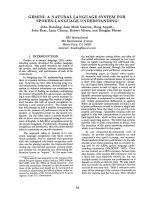
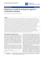
Conception
The introduced Feedback Training System for home
rehabilitation should enable the patient to perform his
rehabilitation exercises on his own responsibility but
controlled at home. Analogue to classic rehabilitation,
the physiotherapist assesses the individual needs of the
patient and defines appropriate training exercises and a
resulting training plan. The exercises are then trained
together with the patient. In this phase, the pat ients
movements are supervised by the therapist and simulta-
neously recorded with the FTS to serve as reference. For
each exercise a reference movement is chosen f rom the
recorded training and stored together with the training
plan in the FTS. In the self dependent training situation
at home the system is attached to the private PC and
presents information about the exercise that has to be
performed according to the training plan. The training
movements are being assessed quantitatively and com-
pared to the reference movements that were defined
previously. If neces sary, adequate visual feedback is dis-
played on the computer screen to help the patient to
identify possible variances in his movements and helping
him to correct them (Figure 1) [38]. The assessed quan-
titative data should also be stored or transmitted to the
therapist for later review [39]. In the end the goal must
be ensuring a training of the desired movement patterns
and enabling the patient to transfer these patterns into
daily activities [40].
The Feedback Training System
The Feedback Training System is based on resistive ele-
ments like gym nastic bands o r tubes. Th ey are cheap,
easy to use and allow resistive training at home. To
characterize a physiotherapeutic exercise, the movement
path, amplitude and speed of the extremities must be
assessed. Since the moved extremities lengthen the resis-
tive element, the resulting force within the element is
proportional to the amplitude an d range of motion. The
range of motion can therefore be estimated by measur-
ing t he force of the resistive element with an adequate
force sensor.
Kohler et al. Journal of NeuroEngineering and Rehabilitation 2010, 7:2
/>Page 2 of 11
Resistive Elements
The mechanical characteristics of resistive e lements are
sim ilar to the ones of rubber as they are mostly derived
from latex or natural rubber. The stress-strain-curve
was measured to define the relation between force and
elongation. The measurements were under taken accord-
ing to DIN 53504 and ISO 527-1 with a shoul der test
bar S2 which is appropriate for elastomeres and natur al
rubber. The non-linear behaviour of t he resistive ele-
ments must be considered when mathematically describ-
ing the resistive elements. Reasonable training
resistances in physiotherapy lie between 10 to 40 New-
ton. The length of the element has to be defined by the
therapist to match the boundary conditions of move-
ment range and resulting force. With the defined le ngth
of the element, the elongation can be c alculated from
measured force values.
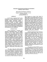
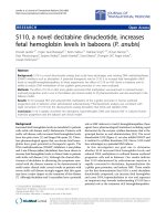
Force Sensor
Since the relation between force and elongation of the
used resis tive elements is known, the assessment of the
one-dimensional fo rce, produced by pulling the resistive
element, allows the calculation of the amplitude of the
movement. A sensor was developed to measure forces
up to 50N with an even higher br eaking stability. It has
to be small and easy to attach between the resistive
element and a handhold. The design shown in Figure 2a
was chosen and optimized for the usual forces of phy-
siotherapeutic training.
Figure 2b shows the stressed areas in the upper part
of the U-shaped aluminium element, when a force is
applied to the sensor. On this location of greates t stress
a resistance strain gauge from Vishay [41] is applied t o
measure the bending of the material as a consequence
of an applied force. Strain gauges change their electrical
resistance with mechanical deformation, especially elon-
gation. The maximum relative lengthening ε of the used
strain gauge is around 0.1%.
The K-facto r for the used strain gauges is 5, therefore
the maximum change in resista nce is expected to be
around 0.5%. To achieve best possible results in measur-
ing such small changes in resi stance, the strai n gauge i s
connected to a PicoStrain PS02 microchip from Acam
[42]. It measures the changes of resist ance in the strains
by discharging a capacitor and measuring time. A sec-
ond strain gauge is placed on the inner side of the alu-
minium sensor, where the material is minimally bent. It
serves for reference temperature measurements. Each
acquisition is sampled with 12bit resolution and takes
about 60 μs. 300 measurements are averaged for one
actual value. The result is digitally transported by a SPI
Figure 1 Concept of Home Rehabilitation.
Kohler et al. Journal of NeuroEngineering and Rehabilitation 2010, 7:2
/>Page 3 of 11
interface to a Atmega 64 microprocessor [43], which
controls the the PS02-Chip and sends the data via USB
to a PC.
Common rehabilitation movements with gymnastic
bands last about 4 to 5 seconds (0.2 Hz -0.25Hz). The
highest reasonable frequencies in visual feedback task s
are about 2 Hz [44-46]. Errors in slow movements
(>500 ms) can be corrected directly using visual feed-
back, especially if the feedback is expected [47]. A
flicker-free visualisation of the feedback can be achieved
with frequencies of 25 Hz or greater. Therefore the
acquisition rate of the whole system is set to 25 Hz.
Figure 2c shows the handles, the U-shaped aluminium
sensor with included electronic and the resistive element
of the final configuration. In the training situation at
home, the sensor can be connected via USB with any
standard PC.
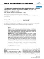
Feedback
The recorded data representing the performed move-
ment must be presented with an adequate visual feed-
back to the patient to allow him to correct errors and to
move accordingly to the individually specified training
plan [48-50]. The PC screen is used to display the visual
feedback. The given task and the corresponding feed-
back must be linked to the clearly defined functional
goal: The regaining of range of motion and with it self-
dependent living to encourage patients to endure in the
feedback task [51]. The feedback control problem must
Figure 2 Sensor Design: (a) Geometry of the force sensor. (b) Stressed area when force is applied to the sensor and placement of strain
gauge. (c) Final sensor with resistive element and handle.
Kohler et al. Journal of NeuroEngineering and Rehabilitation 2010, 7:2
/>Page 4 of 11
be designed in such a way that the patient is not over-
burdened [52,51]. The implementation takes this into
account by presenting a n easy-to-follow online and
direct one-dimensional feedback of the force path (Fig-
ure 3). The recorded data are additionally stored and
can be examined off-line by the therapist to monitor the
rehabilitation progress and interact by changing the
training plan or give additional instructions to the
patient if necessary.
Every rehabilitation exercise with gymnastic bands
shows a characteristic path according to the strength
curve, which is measured with the force sensor. Based
on this path, the feedback is presented. The force path
can be freely defined according to the wished move-
ment. A common rehabilitatio n movement is the slow
and steady stretching and re leasing of t he gymnastic
band with predefined maximum and number of repeti-
tions. The movement is designed in a harmonic way,
sinceeverydaymovementsareusuallyharmonicand
reproduced movements tend to have a bias toward har-
monic movements [53,44]. Each repetition lasts usually
about 4-6 seconds and is rather slow compared to mor e
rapid preprogrammed movements [54-56]. Thus the
patients should be able to use the direct fee dback to
increase the quality of t heir movements [57,47,48]. The
movement pattern allows a certain tolerance from the
pre-set m ovement path. The width b of the corridor is
individually adapted to the patient by the physiothera-
pist. If the performed exercise is within the corridor, the
movements can be considered to be exact enough to
fulfil the therapy needs.
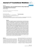
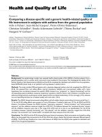
The feedback is presented as an oscilloscope-like
visualisation (Figure 4). T he user sees the given force
path and can anticipate its progression over time
including amplitude, path, speed and number of repeti-
tions. The resulting force of the actual movement is pre-
sented as a moving cursor that draws a path on the
screen, while the user pursues his training movements.
By comparing the given forth path with the actual per-
formed one the user can identify errors and correct
them.
This kind of feedback contributes to the learning
curve, as it helps the patient to evaluate his performance
and update his movement schema in case of errors
[58,49]. In Figure 4 for example the subject can identify
an overshoot in the first shown movement repetition.
Figure 3 Concept of feedback generation based on measured force data.
Figure 4 Visual Online Feedback: Visual Feedback of the given
force path of two repetitions with 5 seconds per movement, a
maximum amplitude of 20N and an allowed corridor of the
width b. The moving Cursor represents the actual force and its
path is displayed as well.
Kohler et al. Journal of NeuroEngineering and Rehabilitation 2010, 7:2
/>Page 5 of 11
For the next repetition, he can adapt the movement
amplitude to fit within the given path.
Mathematical parameters to evaluate training movements
The performed rehabilitation movements are compared
with the corresponding ideal movement that was prede-
termined by a therapist. The comparis on is done with a
set of five parameters. Each parameter was chosen to
indicate the quality of the reproduced movements. If the
training mov ements can be reproduced accurat ely, it can
be assumed that the rehabilitation training would benefit
from using the introduced Feedback Training System.
To each training exercise with resistive elements
belongs an optimal strength path y(t). x
i
(t)represents
the information about the ith repetition of the actual
performed force path. Each repetition x
i
(t)consistsof
M
i
recorded data points. Each training exercise is
trainedasasetwithN repetitions. Sets of different
training exercises form a training plan.
The first parameter that was used to determine the
differences of the actual forces of the subjects compared
to the predetermined ones was the cross correlation
coefficient. It is a measure for the reproducibility of a
movement and gives an idea of the simi larity of two sig-
nals. Since cross-correlations are sensitive to timing
errors [53], the curves wer e shifted until the best fit was
achieved. This also eliminated any possible delays. The
cross correlation coefficient is calculated for each repeti-
tion of the recorded movement. The resulting values
were averaged over the N repetitions to achieve one
measure for the whole training set. The coefficient is 1
if the performed movements are an exact copy of the
given one and reache s the value 0 if the performed
movement fulfils the condition of orthogonality.
The second parameter reflects if the subject reaches
the predetermined maximum amplitude of the force,
respectively the range o f motion and is therefore called
the “Relative Amplitude Error”. For each of the N repe-
titions the locale maximum is determined and the differ-
ence to the given amplitude is calculated. The amplitude
error is normalized to the given amplitude. A value of 0
would be achieved, when the amplitude of the move-
ment matches exactly the pre-set amplitude.
The third parameter gives an idea about the relative
duration error. It compares the length of the actual
movement to the given movement. The parameter is
averaged over the N repetitions of one movement set.
The forth parameter calculates the percentage of the
movement outside of the allowed movement corridor
with the width b and is called the “Outside Parameter”.
While the cross correlation coefficient reflects also small
variations f rom the given movement, the outside para-
meter only takes variations into account, where the
movement exceeds the limitation given by the corrido r.
The corridor width b is given as a percentage of the
maximum desired amplitude and allows variations of
v
1
2
·b in positive and negative direction of the exact
path. T he parameter for the whole training set is then
calculated by equation 3.3.1.
Outside
Abs x
i
y
i
Max y
v
i
N
Length x
() ()
()
100
1
(1)
The outside parameter would indicate a perfect result
for movements that are within the given corridor but ar e
ove rlaid with a tremor for exampl e. Since the movement
should be smooth and steady, a fifth parameter is intro-
duced to calculate the smoothness of the movement.
Smoothness is defined as the average absolute curvature
of the movement performed. Since the M
i
data points of
the recorded force x( t) are equally spaced, the curvature
of repetition i is ca lculated as shown in equation 3.3.2.
Curvature and smoothness are parameters usually used
to describe mathematic functions and have no unit.
Cur
x
i
j
x
i
j
j
M
i
M
i
i
()
(())1
23
1
(2)
The smoothness for one repetition i is the average
absolute value of the curvature and is then averag ed for
each of the N repetitions (3.3.3).
Smoothness
Cur
i
i
N
N
1
(3)
Evaluation
For a proof of concept and to strengthen the hypothesis
that users benefit from visual feedback in the attempt to
reproduce the rehabilitati on movements defined by a
physiotherapist, the FTS was evaluated in a study with
46 young and healthy subjects. The study was approved
by the ethical committee of the medical faculty of the
RWTH Aachen University. The subjects were divided
randomly into two groups. The first group consists of
10 men (26.8 ± 5.3 years) and 6 women (26.7 ± 4.5
years) and received no visual feedback from the FTS.
The second group consi sts of 10 men (27.6 ± 4.7 years)
and 20 women (25.1 ± 6.3 years) and received visual
feedback. If the results of the study are encouraging,
further investigations with elderly and patients with
movement disorders can be made.
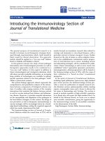
Method
All subjects were right handed and held the handle of
the training device with the right hand and pulled
Kohler et al. Journal of NeuroEngineering and Rehabilitation 2010, 7:2
/>Page 6 of 11
against resistance while the o ther end was connected to
the foot (Figure 5). The occurring forces were between
18N and 24N for all subjects. F or each su bject it was
decided randomly if a either an abduction/adduction
movement or a diagonal PNF pattern should be per-
formed. All subjects were measured in 2 sets of 12 repe-
titions. The abduction/adduction movement begins with
a horizontally extended arm and with dextrally rotated
hand. The arm is then elevated and moved circularly
around the shoulder joint above the head. The PNF
diagonal begins with sinistral rotated stretched out arm
that is held proximal in front of the body. Then the arm
is moved diagonal to a distal position over the head on
the right side while p erforming a supination in the
elbow at the same time, what leads to a dextral Orienta-
tion of the hand (Figure 5). The movement patterns
were taught directly prior to the measurements. Both
groups were treated in the exact same way. The only
difference was that one group w as provided with addi-
tional visual feedback (Fee dback-Group) and the other
group had to perform without visual feedback (Control-
Group).
The subjects performed the movements in two sets
with 12 repetitions leading to 1104 different movement
repetitions, 720 with visual feedback and 384 without.
The movements were examined with the parameters as
mentioned before. Since all parameters were calculated
relative to the pre-set amplitude and given duration, the
results for the two movements, Abduction/Adductio n
and diagonal PNF pattern were combined to compare
both g roups. The aim of this study was to evaluate the
Feedback Training System in view of quality of rehabili-
tation training movements and benefit from the pro-
vided feedback. The effects are being investigated
through the mentioned mathematical parameters calcu-
lated from the measured force values.
For all parameters, the mean values as well as the var-
iances were calculated. For evaluating the differences in
the parameters among different groups, analysis of var-
iance (double-sided T-TEST with unbalanced variances)
was used and calculated with EXCEL. Differences with p
< 5·10
-5
were considered to be statistically significant.
Results
Figure 6 shows the results for the investigated para-
meters. All parameters were plotted with EXCEL as box
plots with minimum, maximum and median value as
well as 25 and 75 percentiles.
On the basis of the recorded force data, the Cross Cor-
relation Coefficient was calculated for each movement
repetition. The reproducibility was then determined
with a mean value of 0.93 ± 0.06 for the Con trol-Group
and 0.99 ± 0.01 for the Feedback-Group. The differences
were significantly different with a p-value of 1.2·10
-9
(Figure 6). The results regarding the corr elation between
the given ideal movement and the actually performed
movements were significant ly better in the Feedback-
GroupthanintheControl-Group.Theabout10times
smaller standard deviation underlines this impression.
Figure 5 Movement Patterns: (a) Abduction-Adduction of the right arm and (b) diagonal PNF Pattern of the right arm.
Kohler et al. Journal of NeuroEngineering and Rehabilitation 2010, 7:2
/>Page 7 of 11
This implies that the feedback significantly improves the
capability of the subjects to reproduce the given force
path.
The Relative Amplitude Error is significantly smaller
in the Feedback-Group (0.03 ± 0.03) than in the Con-
trol-Group (0.06 ± 0.03) with a p-value of 7.6·10
-7
. This
proves that besides the form of the force path also the
amplitude of the force and with it the d esired range of
motion could be reproduced more accurately than in
the Control-Group. As abs olute errors are used, the
information if the amplitude was over- or understepped
cannot be derived. If t he actual movement is compared
to the sharp optimal and given force path without the
allowed movement corridor, it can be found that the
Control-Group pulled 87.5% of the time too hard and
12.5% not hard enough whil e the Feedback-Group over-
stepped the given amplitude 58.3% and understepped it
41.7% of the time. The results of the amplitude variation
are astonishing regarding the allowed movement corri-
dor. The actually achieved variance is smaller than the
allowed variance of
v
1
2
·b = 5% in each direction.
The relative duration error of the Feedback-Group
(0.09 ± 0.13) was si gnificantly smaller than for the Con-
trol-Group (0.33 ± 0.26) with a p-value of p = 2.22·10
-17
(Figure 6). The subjects of the Control-Group seemed
to have fallen into an individual movement speed and
Figure 6 Results for the investigated Parameters: Box Plots for Cross Correlation Coefficient, Relative Amplitude Error, Relative
Duration Error, Outside Parameter and Smoothness Parameter. Each displayed with median, 25% and 75% percentiles as well as minimum
and maximum values.
Kohler et al. Journal of NeuroEngineering and Rehabilitation 2010, 7:2
/>Page 8 of 11
maintained tha t speed quite steady, what is reflected in
the small standard deviation of 0.26. Since the duration
error o nly displays the absolute difference between the
duration of the actual movement and the optimal move-
ment, the duration error was furt her investigated to
answer the question if the duration was over- or under-
steppedwithinthegroups.Itwasfoundthatcompared
to the sharp optimal movement time the mean duration
of the Control-Group movements were 85.4% of all
repetitions too long and 14.6% the movement was to
short. The Feedback-Group repetitions were 78.3% too
long and 21.7% too short.
For the Control-Group the Outside Parameter was
calculated with 0.57 ± 0.16 and for the Feedback-Group
with 0.15 ± 0. 15. The p-value approved statistical differ-
ences with p = 5.96·10
-25
(Figure 6). The par ameter
embraces the above mentioned param eters Cross Corre-
lation Coefficient, Relative Amplitude Error and Relative
Duration Error since it is sensible for movements that
lie outside of the allowed force corridor around the opti-
mal force path. It is therefore not surprising that also
the O utside Parameter states a significant advancement
for the Feedback-Group.
For both groups the Smoothness Parameter was calcu-
lated with 0.02 ± 0.01. The T-Test showed no significant
changes with a p-value of p = 0.24. The Smoothness
Parameter provides information if the feedback task
changes the smoothness and steadiness of movements
comp ared to free movements. It allows an es timation of
how unsteady and turbulent the movement was per-
formed and if these movement characteristics were
negatively influenced by the visual feedback. Since the
parameter shows no statistical changes between the two
groups, it can be suggested that the visu al feedback task
did not have any negative influence on the performed
movement.
Discussion
The combined results showed evidence that the pre-
sented feedback of the FTS improves the capability of
the subjects to reproduce given force paths reflecting
the boundary conditions of form, amplitude and dura-
tion while maintaining the individual smoothness and
steadiness of the movement. Even simple movements
like the presented abduction/adduction and the diagonal
PNF pattern of the arm benefit significantly from the
provided feedback. This supports the idea of improving
the quality of home rehabilitation training with the
introduced system.
These results indicate that the movement speeds are
well within the acc eptable range of direct optical feed-
back [47,59,60]. The mental representation of the move-
ments can be trained further to a higher accuracy
[61,58,49]. This is emphasized by the fact that the given
movement pattern does not change and the frequency is
constant [44].
Since all movement s were overseen by an investigator,
it can be resumed tha t no major movement error
occurred during the tests, though it is imaginable that
subjects perform wrong movements while exercising
with visual feedback. For example, the FTS in the pre-
sented form cannot distinguish between a flexion or
abduction movement. Since a patient has a clear will to
recover as soon as possible it can be assumed that the
subjects are cooperative and want to perform the given
physiotherapeutic movements in the best possible way.
It can also be assumed that many wrong movements
make it impossible for the patient to achiev e the pre-set
force paths and amplitudes, what would also be indi-
cated by bad training results.
It was demonstrated by Todor and Cisneros that the
principle difference of handedness lies in the ability to
accommodate greater precision demands [57]. It must
therefore be expected that the results regarding the
reproduction of given physiotherapeutic movement
paths for the weak side might be not as good in contrast
to the strong side. Learning phases might also be longer
to achieve the same results compared to the strong side.
The introduced Feedback Training System can also be
extended with other additional sensors like the use of
web cams, accelerometers, gyroscopes or magnetometers
to aid more information to the feedback data basis [62].
The FTS fulfils the requirements of a small, cheap and
easy to use t raining device for physiotherapeutic exer-
cises at home. By supporting their efforts with ad equate
online feedback, it supports the patient with guidance
and control, so he can perform the predefined move-
ments with high accuracy. The FTS seemstobeapro-
mising way to support physiotherapeutic training at
home. The results encourage an investigation of the
practicability of the system with elderly patients that are
affected by movement disorders in the upper
extremities.
Conclusion
A Feedback Training System has been introduced that
allows home rehabilitatio n with resistive elements and
provides the patient with guidance and control. It is
cost effective, movabl e, easy to use and assures a higher
quality of movements performed in c omparison to an
uncontrolled unguided home rehabilitation.
Acknowledgements
This study was realized within the research project granted by the Medical
Faculty of the University Hospital Aachen.
Authors’ contributions
FK developed the training system, designed and carried out the study and
the statistical analysis and wrote the manuscript. TSR gave valuable feedback
Kohler et al. Journal of NeuroEngineering and Rehabilitation 2010, 7:2
/>Page 9 of 11
and expert guidance throughout this study and manuscript writing. CDK
participated in the development of the training system and the statistical
analysis, helped revising the manuscript and gave final approval to the
version of the manuscript to be submitted. All authors read and approved
the final manuscript.
Competing interests
The authors declare that they have no competing interests.
Received: 11 November 2008
Accepted: 15 January 2010 Published: 15 January 2010
References
1. Fernando CK, Basmajian JV: Biofeedback in Physical Medicine and
Rehabilitation. Biofeedback and Self-Regulation 1978, 3(4):435-455.
2. Brüggemann S, Korsukéwitz C: Leitlinien in der Rehabilitation:
Einschränkung der Therapiefreiheit oder Grundlage für bessere
Ergebnisse. Rehabilitation 2004, 43:304-311.
3. Jäckel WH, Müller-Fahrnow W, Schliehe F: Leitlinien in der medizinischen
Rehabilitation - Positionspapier der Deutschen Gesellschaft für
Rehabilitationswissenschaften. Rehabilitation 2002, 41:279-285.
4. Jäckel WH, Korsukéwitz C: Leitlinien in der medizinischen Rehabilitation.
Rehabilitation 2003, 42:65-66.
5. Heinemann AW: State of the science on postacute rehabilitation: setting
a research agenda and developing an evidence base for practice and
public policy: an introduction. Journal of NeuroEngineering and
Rehabilitation 2007, 4(43).
6. Lincoln N, Parry R, Vass C: Randomized, controlled trial to evaluate
increased intensity of physiotherapy treatment of arm function after
stroke. Stroke 1999, 30:573-579.
7. Masur H: Sinnvoller Einsatz von Robotern in der Neurorehabilitation -
Fiktion oder Realität. Deutsches Ärzteblatt 2008, 18:329.
8. Woldag H, Waldmann G, Heuschkel G, Hummelsheim H: Is the repetitive
training of complex hand and arm movements beneficial for motor
recovery in stroke patients?. Clinical Rehabilitation 2003, 17:723-730.
9. Hesse S, Schmidt H, Werner C, Bardeleben A: Upper and lower extremity
robotic devices for rehabilitation and for studying motor control. Current
Opinion in Neurology 2003, 16:705-710.
10. Keller A, Asanuma H: Neuronal mechanisms of motor learning in
mammals. NeuroReport 1991, 2:1-30.
11. Hesse S, Bertel C, Schaffrin A, Malezic M, Mauritz K: Restoration of gait in
non-ambulatory hemiparetic patients by treadmill training with partial
body weight support. Archives of Physical Medicine and Rehabilitation 1999,
30:573-579.
12. Colombo G, Joerg M, Schreier R, Dietz V: Treadmill training of paraplegic
patients using a robotic orthosis. Journal of Rehabilitation Research &
Development 2000, 37:313-319.
13. Husemann B, Mueller F, Krewer C, Heller S, Koenig E: Effects of locomotion
training with assistance of a robot-driven gait orthosis in hemiparetic
patients after stroke: a randomized controlled pilot study. Stroke 2007,
38:349-354.
14. Mayr A, Kofler M, Quirbach E, Matzak H, Froehlich K, Saltuari L: Prospective,
blinded, randomized crossover study of gait rehabilitation in stroke
patients using the Lokomat gait orthosis. Neurorehabilitation and Neural
Repair
2007, 21:307-314.
15. Hesse S, Uhlenbrock D: Development of an advanced mechanised gait
trainer, controlling the movement of the centre of mass, for restoring
gait in non-ambulant subjects. Biomedizinische Technik 1999, 44:194-201.
16. Pohl M, Werner C, Holzgraefe M, Kroczek G, Mehrholz J, Wingendorf I,
Hoölig G, Koch R, Hesse S: Repetitive locomotor training and
physiotherapy improve walking and basic activities of daily living after
stroke: a single-blind, randomized multi-centre trail (Deutsche
Gangtrainerstudie, DEGAS). Clinical Rehabilitation 2007, 21:17-21.
17. Wolf LS, Winstein JC, Miller JP, Taub E, Uswatte Gi, Morris D, Giuliani C,
Light EK, Nichols-Larsen D: Effect of constraint-induced movement
therapy on upper extremity function 3 to 9 months after stroke: the
EXCITE randomized clinical trial. Journal of the American Medical
Association 2006, 296(17):2095-2104.
18. Platz T: Evidenzbasierte Armrehabilitation: eine systematische Literatur-
übersicht. Der Nervenarzt 2003, 74:841-849.
19. Hogan N, Krebs H, Charnarong J, Sharon A: Interactive robotics therapist.
1995, US Patent No. 5466213.
20. Aisen M, Krebs H, Hogan N, McDowell F, Volpe B: The effect of
robotassisted therapy and rehabilitative training on motor recovery
following stroke. Archives of Neurology 1997, 54:443-446.
21. Volpe B, Krebs H, Hogan N, Edelstein O, Diels C, Aisen M: A novel
approach to stroke rehabilitation: robot-aided sensorimotor stimulation.
Neurology 2000, 54:1938-1944.
22. Hesse S, Werner C, Pohl M, Rueckriem S, Mehrholz J, Lingnau M:
Computerized arm training improves the motor control of the severely
affected arm after stroke. A single-blinded randomized trial in two
centers. Stroke 2005, 36:1960-1966.
23. Masiero S, Celia A, Rosati G, Armani M: Robotic-assisted rehabilitation of
the upper limb after acute stroke. Archives of Physical Medicine and
Rehabilitation 2007, 88:142-149.
24. Lum P, Burgar C, Shor P, Majmundar M, Loos Van der M: Robot-assisted
movement training compared with conventional therapy techniques for
the rehabilitation of upper-limb motor function after stroke. Archives of
Physical Medicine and Rehabilitation 2002, 83:952-959.
25. Mayr A, Kofler M, Saltuari L: ARMOR: Elektromechanischer Roboter für das
Bewegungstraining der oberen Extremität nach Schlaganfall. Prospektive
randomisierte kontrollierte Pilotstudie. Handchirurgie, Mikrochirurgie,
Plastische Chirurgie 2008, 40:66-73.
26. Kahn L, Zygman M, Rymer W, Reinkesmeyer D: Robot-assisted reaching
exercise promotes arm recovery in chronic hemiparetic stroke: a
randomized controlled pilot study. Journal of NeuroEngineering and
Rehabilitation (JNER) 2006, 3:12-16.
27. Housman S, Le V, Rahman T, Sanchez R, Reinkesmeyer D: Arm-training
with T-WREX after chronic stroke: preliminary results of a randomized
controlled trial. Proceedings of the 2007 IEEE 10th International Conference
on Rehabilitation Robotics, June 12-15, Noordwijk, The Netherlands 2007.
28. Hesse S, Mehrholz J, Werner C: Roboter- und gerätegestützte
Rehabilitation nach Schlaganfall. Deutsches Ärzteblatt 2008, 18:330-336.
29. Werner C, Schmidt H, Sorowka D, Bardeleben A, Hesse S: Automatisierte
motorische Rehabilitation nach Schlaganfall. Physikalische Medizin,
Rehabilitationsmedizin, Kurortmedizin 2003, 16:271-275.
30. Kwekkel G, Kollen B, Krebs H: Effects of robot-assisted therapy on upper
limb recovery after stroke: a systematic review. Neurorehabilitation and
Neural Repair 2008, 22:111-121.
31. Kalra L, Ratan R: Recent advances in stroke rehabilitation 2006. Stroke
2007, 38:235-237.
32. Mavroidis C, Nikitczuk J, Weinberg B, Danaher G, Jenson K, Pelletier P,
Prugnarola J, Stuart R, Arango R, Leahey M, Pavone R, Provo A, Yasevac D:
Smart portable rehabilitation devices. Journal of NeuroEngineering and
Rehabilitation 2005, 2(18).
33. Johnson M, Feng X, Johnson LM, Winters JM: Potential of a suite of robot/
computer-assisted motivating systems for personalized, homebased,
stroke rehabilitation. Journal of NeuroEngineering and Rehabilitation 2007,
4(6).
34. Dvorkin AY, Kenyon RV, Keshner EA: Reaching within a dynamic virtual
environment. Journal of NeuroEngineering and Rehabilitation 2007, 4(23).
35. Kenyon RV, Leigh J, Keshner EA: Considerationsfor the future
development of virtual technology as a rehabilitationtool. Journal of
NeuroEngineering and Rehabilitation 2004, 1(13).
36. Sveistrup H: Motor rehabilitation using virtual reality. Journal of
NeuroEngineering and Rehabilitation 2004, 1(10).
37. Basmajian JV: Biofeedback: principles and practice for clinicians.
Williams@Wilkins , 3 1989.
38. Elliot D, Chua R, Pollock BJ, Lyons J: Optimizing the Use of Vision in
Manual Aiming: The Role of Practice. The Quaterly Journal of Experimental
Psychology 1995, 48A(1):72-83.
39. Wang Z, Kiryu T, Tamura N: Personal customizing exercise with a
wearable measurement and control unit. Journal of NeuroEngineering and
Rehabilitation 2005, 2(14).
40. Matsuoka Y, Brewer BR, Klatzky RL: Using visual feedback distortion to
alter coordinated pinching patterns for robotic rehabilitation. Journal of
NeuroEngineering and Rehabilitation 2007, 4(17).
41. Datasheet of Strain Gauge: FAE-A6172G-100-SXE, Vishay Measurements
Group GmbH. .
42. Datasheet of PS02 picostrain, Acam mess electronics. m.
de.
Kohler et al. Journal of NeuroEngineering and Rehabilitation 2010, 7:2
/>Page 10 of 11
43. Datasheet of ATmega 64 microprocessor, Atmel Cooperation. http://
www.atmel.com.
44. Mather JA, Putchat C: Parallel Ocular and Manual Tracking Responses to
a Continuously Moving Visual Target. Journal of Motor Behavior 1983,
15(1):29-38.
45. von Noorden GK, Mackensen G: Pursuit Movements of Normal and
Amblyopic Eyes. American Journal of Opthalmology 1962, 53:325-336.
46. Mather JA, Lackner JR: Visual tracking of active and passive movements
of teh hand. Quaterly Journal of Experimental Psychology 1980, 32:307-315.
47. Brenner E, Smeets JBJ: Fast Responses of the Human Hand to Changes in
Target Position. Journal of Motor Behavior 1997, 29(4):297-310.
48. Zelaznik HN, Hawkins B, Kisselburgh L: Rapid Visual Feedback Processing
in Single-Aiming Movements. Journal of Motor Behavior 1983, 15(3):217-
236.
49. Ivens CJ, Marteniuk RG: Increased Sensitivity to Changes in Visual
Feedback With Practice. Journal of Motor Behavior 1975, 82(4):225-260.
50. Huang H, Ingalls T, Olson L, Ganley K, Rikakis T, He J: Interactive
Multimodal Biofeedback for Task-Oriented Neural Rehabilitation.
Proceedings of the 2005 IEEE, Engineering in Medicine and Biology 27th
Annual Conference 2005, 2547-2550.
51. Huang H, Wolf SL, Jiping H: Recent developments in biofeedback for
neuromotor rehabilitation. Journal of Euro Engineering and Rehabilitation
2006, 3.
52. Desimone R, Duncan R: Neural Mechanisms of Selective Visual Attention.
Annual Review of Neuroscience 1995, 18:193-222.
53. Heuer H: The Timing of Human Movements. Neural Bases of Motor
Behaviour 1996, 261-314.
54. Schmidt RA, Zelaznik HN, Hawkins B, Frank JS, Quinn JT: Motor-output
variability: A theory for the accuracy of rapid motor acts. Psychological
Review 1979, 86:415-451.
55. Keele SW, Posner MI: Processing of visual feedback in rapid movements.
Journal of Experimental Psychology 1968, 77(1):155-158.
56. Kunesch E, Binkofski F, Freund H-J: Invariant tgemporal characteristics of
manipulative hand movements. Experimental Brain Research 1989, 78:539-
546.
57. Todor J, Cisneros J: Accomodation to Increased Accuracy Demands by
the Right and Left Hands. Journal of Motor Behavior 1985, 17(3):355-372.
58. Schmidt RA: A Schema Theory of Discrete Motor Skill Learning.
Psychological Review 1975,
82(4):225-260.
59. Leist A, Freund H-J, Cohen B: Comparative characteristics of predictive
eye-hand tracking. Human Neurobiology 1987, 6:19-26.
60. Hay L, Beaubaton D: Visual Correction of a Rapid Goal-Directed Response.
Perceptual and Motor Skills 1986, 62:51-57.
61. Soechting JF, Flanders M: Errors in Pointing are Due to Approximations in
Sensorimotor Transformations. Journal of Neurophysiology 1989, 62(2):595-
608.
62. Weiss PL, Rand D, Katz N, Kizony R: Video capture virtual reality as a
flexible and effective rehabilitation tool. Journal of NeuroEngineering and
Rehabilitation 2004, 1(12).
doi:10.1186/1743-0003-7-2
Cite this article as: Kohler et al.: Introducing a feedback training system
for guided home rehabilitation. Journal of NeuroEngineering and
Rehabilitation 2010 7:2.
Publish with Bio Med Central and every
scientist can read your work free of charge
"BioMed Central will be the most significant development for
disseminating the results of biomedical research in our lifetime."
Sir Paul Nurse, Cancer Research UK
Your research papers will be:
available free of charge to the entire biomedical community
peer reviewed and published immediately upon acceptance
cited in PubMed and archived on PubMed Central
yours — you keep the copyright
Submit your manuscript here:
/>BioMedcentral
Kohler et al. Journal of NeuroEngineering and Rehabilitation 2010, 7:2
/>Page 11 of 11