báo cáo hóa học: " An instrumented cylinder measuring pinch force and orientation" docx
Bạn đang xem bản rút gọn của tài liệu. Xem và tải ngay bản đầy đủ của tài liệu tại đây (406.39 KB, 10 trang )
BioMed Central
Page 1 of 10
(page number not for citation purposes)
Journal of NeuroEngineering and
Rehabilitation
Open Access
Research
An instrumented cylinder measuring pinch force and orientation
Daniel Bourbonnais*
1,2
, Victor Frak
1,2,3
, Jean-François Pilon
1
and
Michel Goyette
1
Address:
1
Centre de recherche interdisciplinaire en réadaptation du Montréal métropolitain (CRIR), site Institut de réadaptation de Montréal,
Montréal, QC, H3S 2J4, Canada,
2
École de réadaptation, Faculté de médecine, Université de Montréal, QC, H3C 3J7, Canada and
3
Département
de kinanthropologie, Université du Québec à Montréal, QC, H3C 3P8, Canada
Email: Daniel Bourbonnais* - ; Victor Frak - ; Jean-François Pilon - jean-
; Michel Goyette -
* Corresponding author
Abstract
Background: The function of a cylinder allowing simultaneous measurements of the opposition
axis of the index finger and thumb of the hand and the magnitude of pinch force is described.
Methods: The apparatus is made of two half-cylinders that are bonded together through a 6-axis
force/torque sensor and allows the measurement of 3D orthogonal forces and moments of force.
The amplitude of the pinch force exerted on the cylinder by the fingers is defined as the resultant
of the forces in the different axes. A software program was developed to measure the barycentre
of the forces on the instrumented cylinder, allowing calculation of the angle of the opposition axis
between the fingers and the location of the resulting pinch force on the cylinder, assuming that the
pinch or grip forces are co-linear through the center of the cylinder.
In order to assess the validity and reliability of the measurements, the cylinder was mounted on a
milling table and seven calibrated weights (from 100 to 500 g) were successively applied
perpendicularly to a 9*9 matrix of sites separated by 1 cm. With the exception of the extreme
lateral parts of the cylinder, the dispersion of the calculated vertical position of the resulting force
was always within 1 mm of the application point, suggesting a high reliability of these measurements.
In addition, the errors in the angles of the applied force were calculated and found to be less than
2 degree with no clear patterns of variation across the different locations of the cylinder.
Results: The usefulness of the cylinder is demonstrated by evaluating the pinch force and the
opposition axis in six healthy subjects lifting the cylinder from the table using three different
orientations of their right hand. The magnitude of the grip force was not significantly different
across orientations (45, 22 and -22 degrees relative to the midline of the subject) suggesting that
force grip is controlled.
Conclusion: From these results, it has been concluded that the cylinder is a valid, reliable and
precise instrument that may prove useful for evaluating opposition axis and grip force in healthy
and pathological populations.
Published: 2 January 2008
Journal of NeuroEngineering and Rehabilitation 2008, 5:2 doi:10.1186/1743-0003-5-2
Received: 8 March 2007
Accepted: 2 January 2008
This article is available from: />© 2008 Bourbonnais et al; licensee BioMed Central Ltd.
This is an Open Access article distributed under the terms of the Creative Commons Attribution License ( />),
which permits unrestricted use, distribution, and reproduction in any medium, provided the original work is properly cited.
Journal of NeuroEngineering and Rehabilitation 2008, 5:2 />Page 2 of 10
(page number not for citation purposes)
Introduction
Grasping, holding and manipulating objects represent
one of the most important functions of the hand. During
the phase where the hand is brought into the vicinity of
the object to be manipulated, the grasp aperture increases
to reach a maximum before contact with the object and is
adjusted precisely when the hand is close to the object [1].
In addition to controlling the aperture of the fingers, the
orientation of the hand relative to the object is critical for
effective manipulation. The grasp orientation as described
by Napier [2] is determined from the configuration of the
arm and the hand that the nervous system has to define in
order to allow utilization of an object [3-5]. Moreover, the
positions of the fingers on the object need to be deter-
mined by the nervous system to ensure secure manipula-
tion. For example, pinching a cylinder requires the
opposition of the index and the thumb to be approxi-
mately through the center of the object to ensure stability
of the grip. The location, size and weight of the cylinders
do not impact on the grasp orientation or the opposition
axis, which remain stable with respect to an egocentric
reference frame in right-handed individuals [6].
In addition to this spatial consideration, lifting and hold-
ing an object between the index finger and thumb
requires fingertip shear forces to overcome the weight of
the object and prevent it from dropping. The amplitude of
the shear force is determined by the friction coefficient of
the object and the amplitude of the grip force (GF, consid-
ered as the finger force acting perpendicularly to the
object's surface). To avoid slipping and/or dropping of the
object, the GF must therefore be modulated as a function
of the friction coefficient and weight of the object [7,8].
Usually, subjects exert a slightly larger GF than the GF
mechanically required to hold the object, providing a
safety margin that allows small perturbations to be cor-
rected without dropping the object [8]. Many studies have
demonstrated the precise coordination between the GF
and the shear forces during the manipulation of an object
[8-11] but few have characterized their changes or magni-
tudes when the opposition axis or orientation of the hand
is modified. Typically, the opposition axis is determined
by the location of force transducers not allowing a person
who lifts an object to select his/her preferred grasp orien-
tation. This provides a rationale for developing an instru-
mented cylinder measuring both the amplitude of the
pinch force and allowing self-selection or imposed orien-
tation of the opposition axis. The precision of the meas-
urements obtained from such an apparatus was
investigated experimentally in the present study. Moreo-
ver, its usefulness is illustrated by exploring changes in GF
across different configurations of the arm and hand while
the individual is lifting the cylinder.
Methods
Experimental set-up
An instrumented cylinder (diameter of 60 mm and a height
of 100 mm) having dimensional characteristics similar to
everyday-life objects such as a glass or a bottle was built to
allow the opposition axis and force magnitude to be meas-
ured while it is manipulated. The external frame of the cyl-
inder consists of two separate nylon 66 half-cylinders
rigidly connected to a single 6-axis force/torque (F/T) sen-
sor (ATI Industrial Automation, NC, USA, model Mini 40
SI-20-1 with a resolution in each channel: F
X
, F
Y
= 1/100 N;
F
Z
= 1/50 N; T
X
, T
Y
, T
Z
= 1/4000 Nm). All forces and
moments of force exerted by the fingers are measured
through the transducer since the two half-cylinders are sep-
arated by a gap of 0.56 mm. One of the half-cylinders is
press-fitted and locked with set screws on an adapter that
was fixed on the sensitive side ("tool side" as defined by ATI,
see Figure 1C) of a single F/T sensor, enabling external
forces and torques to be recorded (Figures 1A and 1C). The
adapter consists of a machined hat-shaped nylon plate per-
mitting adequate transfer of the forces and moments from
the half-cylinders to the F/T sensor (Figures 1A and 1C,
hatched area). The forces exerted on the non-sensitive half-
cylinder are considered equal and opposite to the ones
recorded on the opposite half-cylinder, assuming that sta-
ble manipulation of the instrumented cylinder is achieved.
In conjunction with the instrumented cylinder, a software
program was developed (LabView v6.1, National Instru-
ments, TX, USA) to record and process the 6-axis data
from the F/T sensor. The software program provides a real-
time display and recording of the experimental variables
of interest, namely, opposition axis (
θ
), height (x) and
resulting force (P) of the weight applied to the instru-
mented cylinder (Figure 1A). The center of pressure is
expressed in terms of the angle and height of the force act-
ing on the surface of the cylinder due to the applied loads
(
θ
and x values in Figure 1A). All variables are obtained
from computations based on the instrumented-cylinder
characteristics (e.g. relative position of the F/T sensor,
diameter) and measurements of the XYZ decomposed
forces (F) and moments (M) captured from the F/T sensor
embedded inside. The opposition axis was considered col-
linear through the cylinder's central axis. The program
used the following equations to compute the variables of
interest in a cylindrical coordinates referential (r,
θ
, and x,
where r is fixed here to the radius of the cylinder and x
0
is
the position of the center of the F/T sensor relative to the
top of the cylinder).
θ
=
⎛
⎝
⎜
⎜
⎞
⎠
⎟
⎟
−arctan
F
Z
F
Y
90
(1)
Journal of NeuroEngineering and Rehabilitation 2008, 5:2 />Page 3 of 10
(page number not for citation purposes)
Calibration
The instrumented cylinder was calibrated using precision
devices including an angular positioning tool (milling
table) and a linear positioning plate (Figure 1C). The cyl-
inder was firmly clipped horizontally on the angular posi-
tioning tool in order to be able to rotate it and to measure
the weights vertically applied to its surface. The angular
positioning tool had a vernier, giving a measurement pre-
cision of 0.1°, while the positioning plate comprised cir-
cular, center-spaced holes of 1 cm in which the weight
support could be inserted. The weight support had a
pointed tip allowing the standard weights to be placed
precisely (combination of angle and height) on the sur-
face of the cylinder. Also, the weight of this support was
subtracted from the load measured by the cylinder, since
a baseline was established before recording began, while
the weight support was in contact with the surface. With
the instrumented cylinder weighing approximately 100 g,
the range of weights used for the calibration was dictated
by the most probable forces exerted by a subject manipu-
lating the object. Multiple combinations of standard
weights (100, 200, 300, 400 and 500 g) and positions
(angles ranging from -80° to 80° in increments of 20°,
with 0° being aligned with the center of the force cell flat
surfaces; height ranging from 10 to 90 mm in increments
of 10 mm from the top of the cylinder; see Figures 1A and
1C) were used for the purpose of calibration (5 weights ×
9 angles × 9 heights = 405 combinations). The opposition
axis (
θ
), height of precision grip (x) and resulting force (P)
were averaged for each combination from 500 data points
acquired during a 5-s acquisition period at 100 Hz.
Empirical data processing for calibration
A descriptive statistical analysis including computation of
means, standard deviations (SD), confidence intervals at
95% (CI) and absolute error (AE) of each P value
obtained was performed on the calibration data recorded
when applying a given weight to the cylinder at the differ-
ent locations (x and
θ
). For the center of pressure (COP)
variables (
θ
, x), the mean, SD, CI and AE values were com-
puted by averaging data for the different weights applied
to the cylinder for each combination of
θ
and x (matrix of
9 × 9, see Figure 1C).
The weights used to determine the amplitude of P were
precise (1000 g × 10 g Brass Hook Weight Set, item#
46206-00, Ohaus, USA) and were used as gold standards.
In contrast, the experimental set-up had its own sources of
error regarding the location of the applied force, as will be
addressed later in the discussion. Thus, for the COP varia-
bles, the theoretical values of
θ
or x chosen in the spatial
referential determined by the experimental set-up (see
Figure 1C) were considered as absolute while their aver-
aged values over all the weights and for all
θ
or x (depend-
ing on the variable of interest) were used to obtain gold
xx
rF
X
M
Y
F
Z
=−
⋅⋅ −
0
cos
θ
(2)
P FFF
XY Z
=++
222
(3)
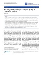
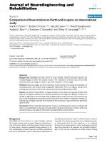
Functioning of the instrumented cylinder and experimental set-up used for its calibrationFigure 1
Functioning of the instrumented cylinder and experimental
set-up used for its calibration. The apparatus is designed to
measure the orientation (
θ
) and vertical location (x) of the
applied force (P) by either the index or thumb while exerting
a grip force (in A and B). These parameters are calculated
from outputs of an F/T sensor (with axes X, Y and Z) embed-
ded in the two half-cylinders using two T-adaptors (upper
panel of A and C; T-adaptors indicated in hatched, the F/T
sensor in black). In order to verify the accuracy of measure-
ments, the cylinder was mounted on an angular positioning
tool by clipping one of its ends, aligned horizontally, on a mill-
ing table (not illustrated) and we used a linear positioning
plate (2 upper panels of C), in order to apply five different
masses (P in 2 upper panels of C: 100, 200, 300, 400 and 500
g) vertically on each point of the matrices formed by the nine
angles (-80° to +80°) and nine heights (10 to 90 mm) and
indicated by the dashed lines. The sensitive side of the trans-
ducer is the one linked to the half-cylinder with only the T-
adaptor inside it and not the body of the transducer (in
black) itself (upper panels of A and C).
P
Z
Y
X
Z
Y
A
B
C
P
10 20
30
40 50 607080 90
20
40
60
80
0
90
x
0
x
x
q
r
20
40
60
80
-80
-60
-40
-20
P P
20
40
60
80
-80
-60
-40
-20
0
10 20
30
40 50 607080 90
P=(F +F +F )
xyz
222½
P
P
Journal of NeuroEngineering and Rehabilitation 2008, 5:2 />Page 4 of 10
(page number not for citation purposes)
standards. Before obtaining gold standards, we intended
to minimize the difference between all points from the
absolute referential and the averaged values computed for
all
θ
or all x in order to detect a possible systematic error
introduced in the measurements by the experimental set-
up. The AEs difference between expected theoretical value
and averaged empirical value) on the COP variables indi-
cated a tendency in the measurements to systematically
over- or undershoot the expected measures. Concretely,
the measurements for the angles tested were averaged for
all weights and heights tested at a single angle and vice-
versa for the heights tested. This procedure revealed a sys-
tematic offset of about 1.5° and 0.5 mm between the the-
oretical referential and the computed means of angle and
height measurements, respectively. This offset was always
over (heights) or under (angles) the expected values, rep-
resenting a systematic error in the empirical data that we
subtracted from all the empirical measurements, i.e.
before obtaining the COP gold standards. The AEs on the
COP variables were then computed as the difference
between the mean of the variable of interest over all the
weights at a specific point (
θ
, x) and the gold standards
(both corrected for systematic offset), while the AEs on
weights were simply the difference between the measured
and standard weights used during calibration.
For P statistics, the use of standard weights (gold stand-
ards) allowed us to compare each measurement with a
specific weight (9 heights × 9 orientations = 81 combina-
tions) to the real weight applied. On the other hand, to
determine the spatial precision and accuracy of the instru-
mented cylinder measurements, we relied on means, SDs
and CIs given by the frequency distribution of the COP
variables. Means and SDs allowed us to verify that the dis-
tributions of COP variables were centered near the
expected values (based on the calibration set-up referen-
tial) and presented a narrow deviation from the average,
which produced a high precision and accuracy. CIs gave us
another way of visualizing the precision of the instru-
ment, since 95% of the measurements performed lie
within the range of the CI.
Variations of pinch force using different orientations
Six subjects (two men and four women aged between 21
and 45 years old) participated in the study. This experi-
ment was approved by the research ethics committee of
our institution and all participants gave their informed
consent before the study began. All subjects were right-
handed, as evaluated using the 'Edinburgh Handedness
Inventory' (Oldfield, 1971). The subject sat on a chair
without armrests facing the instrumented cylinder placed
at his/her midline on a table. His/her trunk was located 15
cm from the edge of the table, 32.5 cm from the cylinder,
which was placed on the table (Figure 2). The subject's
hands were placed on the table, 12 cm each side of the
midline. At the request of the experimenter, the subject
was asked to reach, pinch and lift the cylinder at his/her
own pace with the right thumb and index finger pads to a
height of approximately 10 cm and maintain this position
for 10 s (Figures 1B and 2). The finger pads had to be
aligned with one pair of colour markers (red: 45°, green:
22° and yellow: -22°) visible on the top of the instrument
and indicating the approximate opposition axis required.
Only visual inspection by the experimenter was used to
determine whether subjects had used the opposition axis
required and the exact opposition axis was calculated
using the instrumented cylinder. It is important to note
that the reference axis for the angle measurements is the Z
axis of the transducer, as shown in Figure 1A. Therefore,
each marker pair was positioned on the top extremities at
clockwise angles relative to the subject's medial line (see
Figure 2). Ten trials were performed for each of the three
different orientations (45°, 22° and -22°). The wrist joint
amplitude was measured with an electro-goniometer
(model SG65, Biometrics Ltd., UK). Each condition was
evaluated 10 times and the order was randomly adminis-
tered for each subject. The amplitude of the force applied
by the finger pads (P), their opposition axis (
θ
) and their
height (x) relative to the top of the cylinder were given by
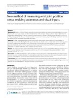
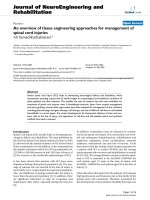
Experimental set-up for testing grasps orientationsFigure 2
Experimental set-up for testing grasps orientations. A subject
is required to execute successive series of lifts of the instru-
mented cylinder to a height of approximately 10 cm using his
right hand with the finger pads aligned at different orienta-
tions identified by colour markers on the top of the cylinder
(dashed: 45°, black: 22° and white: -22°).
Instrumented
cylinder
15 cm
32.5 cm
24 cm
hand
departure
points
-22 22
45
Journal of NeuroEngineering and Rehabilitation 2008, 5:2 />Page 5 of 10
(page number not for citation purposes)
the instrumented cylinder. The movement was divided
into two main phases: a dynamic phase, when the object
is lifted from the table, and a static phase, when the object
is stabilized in the air before being deposited on the table.
These two phases were chosen because the grip forces
observed during the dynamic phase were noticeably dif-
ferent from those measured during the static phase due to
the inertial forces caused by acceleration and deceleration
of the object and the following adaptation of grip force
while maintaining the object in the air [10,12]. The begin-
ning of the dynamic phase corresponded with the onset of
the GF and was determined as the first point exceeding 2
SD from the mean baseline of GF and having a positive
derivative of GF (dGF) for at least six consecutive points.
The end of the dynamic phase was temporally defined as
1450 ms after the first minimal amplitude of dGF follow-
ing the maximal amplitude of GF. This period of 1450 ms
was arbitrarily chosen after visualizing numerous empiri-
cal signals. We analyzed the data for two selected periods
of 250 ms measured respectively while the subject lifted
the object in the air (maximal amplitude of the dynamic
period) and about 5 s after the subject had been holding
the object in the air (middle of the static period). The
pinch force value and the parameters of the axis of oppo-
sition were then averaged in these two windows.
Results
Angle, height and weight (force) calibration measurements
As presented in Figures 3A, 4A and Table 1, no clear pat-
tern could be identified in the empirical errors calculated
relative to the mean of the experimental angles, using the
five different weights at the different locations of the cyl-
inder surface. The empirical errors are shown for all angles
(abscissa) and all heights (x axis) tested (see legend). No
clear patterns were observed across the different angles
and heights tested. The angular mean AE and mean vari-
ance for all the locations on the cylinder are respectively
0.48° and 1.65° (mean SD = 1.13°).
The amplitude of the errors for the experimental heights
was higher at the extreme angles and at lower heights (Fig-
ures 3B, 4B and Table 2) of the half-cylinder, resulting in
an asymmetrical bowl-shaped distribution. The mean AE
and mean variance of the heights were 0.43 mm and 0.83
mm respectively (mean SD = 0.66 mm).
Finally, the magnitudes of the applied forces (weights)
were calculated for all locations tested and the mean val-
ues and the errors are presented in Table 3. The difference
between the applied force and the measured force by the
transducer was less than 0.165 N for the range applied
(0.19 N to 4.9 N). The mean AE ranged from 0.014 N to
0.034 N for all the weights used while the coefficients of
variations ranged from 0.006 to 0.049.
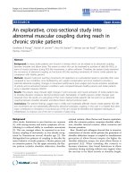
Pinch force across opposition axes
The amplitude of the forces (P) measured during the
dynamic (max) and static (mid) phases of the manipula-
tion of the cylinder for the different opposition axes is
illustrated in Figure 5 and summarized in Table 4. The
ANOVAs indicate that the forces (P) exerted did not differ
across the different opposition axes for both the dynamic
(F(2,10) = 0.538 p = 0.573) and static phases (F(2,10) =
1.03 p = 0.369).
The mean axis of opposition measured by the apparatus
during the dynamic and static phases was significantly dif-
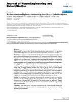
A) Distribution of the 95% confidence intervals for empirical angles recorded during the calibration of the instrumented cylinderFigure 3
A) Distribution of the 95% confidence intervals for empirical
angles recorded during the calibration of the instrumented
cylinder. Results are averaged for all the weights. B) Same
confidence intervals but for calculated heights.
80
60
40
20
0
-20
-40
-60
-80
10
20
30
40
50
60
70
80
90
0
0.5
1
1.5
2
2.5
3
3.5
4
ANGLE (°)
HEIGHT (mm)
HEIGHT CI (mm)
B
80
60
40
20
0
-20
-40
-60
-80
10
20
30
40
50
60
70
80
90
0
0.5
1
1.5
2
2.5
3
3.5
4
ANGLE (°)
HEIGHT (mm)
ANGLE CI (°)
A
Journal of NeuroEngineering and Rehabilitation 2008, 5:2 />Page 6 of 10
(page number not for citation purposes)
ferent from the required angles for both the 22° and 45°
orientations (t values varying between 6.82 and 11.25 and
p value situated between 0.001 and 0.0001) but not for
the -22° orientation (t values -0.810 and 2.36 with a p
value of 0.455 and 0.064 respectively for the dynamic and
static phases). This difference between the required and
measured orientation is probably associated with visuo-
motor mechanisms that caused uncertainties in the spatial
positioning of the fingers on the object.
The mean heights were significantly different across orien-
tations for both the dynamic (F(2,10) = 4.55 p = 0.047)
and static phases (F(2,10) = 11.67 p < 0.02). Contrast
analyses indicated that the height in the direction of -22°
differs from 22° and 45° for both the dynamic (t = 2.80;
p = 0.038; t = 2.76; p = 0.04) and static phases (t = 2.80 p
= 0.038; t = 5.83 p = 0.002).
The joint amplitude of the wrist was also measured at the
dynamic and static phases and differs for the different
opposition axes. The ANOVAs indicate that the joint
amplitude measured is different across the different orien-
tations for both the dynamic (F(2,10) = 188.28 p < 0.001)
and static phases (F(2,10) = 177.36 p < 0.001). Post-hoc
analyses indicate that the joint amplitudes differ between
each of the different opposition axes for both the dynamic
and static phases.
Discussion
The functioning of a cylinder allowing the axis of opposi-
tion and the magnitude of the force applied between the
index finger and thumb to be measured during a pinch is
described. Experimental errors in measurements were
evaluated and the application of the apparatus was
demonstrated by measuring the pinching forces at three
different orientations in healthy subjects.
In order to calibrate the cylinder, weights were applied
vertically through a positioning plate at different loca-
tions on the surface of the cylinder. The different loca-
tions were tested by rotating the cylinder (angles) using
a milling table and using different holes of the position
plate (heights). This experimental set-up generated sys-
tematic and random errors, thus affecting the location
and the magnitude of the applied force. One example of
such a systematic error, given in the Results section, was
probably due mainly to the initial position of the object
in the calibration set-up, which was evaluated visually
using a ruler. In addition, the fitting of the force/torque
sensor inside the cylinder was slightly imperfect,
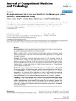
A) Distribution of the absolute error between the angles computed by the instrumented cylinder and the expected angles (absolute referential) at all angles and heightsFigure 4
A) Distribution of the absolute error between the angles
computed by the instrumented cylinder and the expected
angles (absolute referential) at all angles and heights. B) Same
absolute errors but for heights.
0.00
0.50
1.00
1.50
2.00
2.50
80 60 40 20 0 -20 -40 -60 -80
Angles (°)
Angle Absolute Error (°)
10
20
30
40
50
60
70
80
90
0.00
0.50
1.00
1.50
2.00
2.50
3.00
3.50
4.00
80 60 40 20 0 -20 -40 -60 -80
Angles (°)
Height Absolute Error (mm)
10
20
30
40
50
60
70
80
90
A
B
Table 1: Angle measurement precision evaluated by different indicators based on absolute (mean and standard deviation – SD), root
mean square (RMS) and maximum (max.) errors.
Theoretical
Angle Tested 80.00 60.00 40.00 20.00 0.00 -20.00 -40.00 -60.00 -80.00
Empirical Angles
Mean* (N) 80.47 59.48 40.14 20.13 -0.25 -20.237 -40.05 -60.00 -79.66
Mean SD (N) 0.91 1.55 1.54 1.04 1.15 1.255 0.95 0.84 0.96
Mean Error** (N) 0.49 0.64 0.56 0.32 0.54 0.654 0.42 0.31 0.38
SD Error (N) 0.38 0.43 0.48 0.41 0.54 0.699 0.31 0.20 0.16
RMS Error (N) 0.61 0.75 0.72 0.50 0.74 0.928 0.51 0.37 0.41
Max Error (N) 1.25 1.21 1.52 1.30 1.87 2.130 1.02 0.72 0.66
* Corrected for systematic offset of -1.51°.
** Relative to the corrected empirical mean
Journal of NeuroEngineering and Rehabilitation 2008, 5:2 />Page 7 of 10
(page number not for citation purposes)
potentially contributing to the systematic error in the
torque and force measurements due to an incorrect
alignment of the sensor with respect to the cylinder.
However, a procedure was implemented to take into
account the systematic errors occurring due to misalign-
ment of either the applied force and/or the position of
the cylinder under the positioning plate set using the
milling table. Systematic errors of 1.51 mm and 0.51°
were calculated and removed from the averaged values of
COP variables in order to obtain gold standards as close
as possible to the theoretical values. In addition, random
errors in the angle or height measurements may result
from slight displacements of the weight support within
the guide system and also from errors occurring while
positioning the cylinder using the milling table. The
slight misalignments of the applied force with respect to
the referential coordinates of the force transducer may
generate an error in the magnitude of force, since the
force is exerted at a slight angle. Nonetheless, assuming
that this angle value is small, these errors were estimated
to be very low, since they vary as a cosine function. That
being said, the slight misalignment of the weight support
inserted into the guide hole of the positioning plate and
the uncertainties in the positioning of the cylinder under
the position plate using the milling table can also intro-
duce an error in the location of the applied force, gener-
ating a source of error in the angle and height
measurements. We estimated visually that the maximal
random error in the positioning of the applied force on
the cylinder is approximately 0.5 mm, which is close to
the mean AE calculated for heights (Figure 4B). Since the
cylinder has a radius of 3.0 cm, we calculated that an
error of location of 0.5 mm would correspond to an
angular error of approximately 1°, which is also close to
Table 2: Height measurement precision evaluated by different indicators based on absolute (mean and standard deviation – SD), root
mean square (RMS) and maximum (max.) errors.
Theoretical
Heights
Tested
10.00 20.00 30.00 40.00 50.00 60.00 70.00 80.00 90.00
Empirical Heights
Mean*
(mm)
10.19 20.01 30.18 40.15 50.12 59.77 69.74 80.01 89.71
Mean SD
(mm)
0.56 0.41 0.47 0.81 0.78 0.71 0.72 0.86 0.87
Mean
Error**
(mm)
0.37 0.46 0.32 0.89 0.29 0.22 0.49 0.68 0.18
SD Error
(mm)
0.44 0.45 0.29 1.13 0.16 0.17 0.48 0.92 0.11
RMS Error
(mm)
0.55 0.63 0.42 1.39 0.32 0.27 0.67 1.10 0.21
Max Error
(mm)
1.17 1.42 0.83 3.54 0.58 0.49 1.38 3.06 0.36
* Corrected for systematic offset of 0.51 mm
** Relative to the corrected empirical mean
Table 3: Weight measurement precision evaluated by different indicators based on absolute (mean and standard deviation – SD), root
mean square (RMS) and maximum (max.) errors.
Theoretical
Mass tested (g) 100 200 300 400 500
Weight (N) 0.981 1.961 2.942 3.922 4.903
Empirical Weights
Mean (N) 0.991 1.982 2.968 3.948 4.924
SD (N) 0.014 0.015 0.025 0.030 0.031
Mean Error (N) 0.014 0.022 0.032 0.034 0.029
SD Error (N) 0.009 0.013 0.017 0.021 0.025
RMS Error (N) 0.017 0.026 0.036 0.039 0.038
Max Error (N) 0.035 0.057 0.088 0.082 0.165
Journal of NeuroEngineering and Rehabilitation 2008, 5:2 />Page 8 of 10
(page number not for citation purposes)
the AEs that were estimated (Figure 4A). Other random
sources of error could be due to the mechanical assem-
bling of the two separate half-cylinders. These parts were
slightly separated and the compliance of the material
could introduce a change in the radius of the cylinder
while applying forces on it. However, it was carefully ver-
ified that no contact between the two halves of the cylin-
der occurred within the range of force tested. Finally, the
minimal resolution of the force/torque sensor, which is
of the order of 1/50 N for force and 1/4000 Nm, also
contributes to the random error of measurement.
In sum, although different sources of error could
affect the validity of height and angular
measurements, their empirical estimations were
found to be rather small (less than 0.5 mm and less
than 1.0°).
The results indicate no clear pattern or difference in the
AEs of angular measurements across the surface of the
cylinder. In contrast, the AEs in the height measurements
tend to increase as the force application is displaced lat-
erally (towards +80° or -80°) or, to a lesser degree, dis-
tally (towards 90 mm). This height is defined in the X
coordinates of the sensor (Figure 1A) and estimated by
the ratio of torques and force components in the Z axis.
In contrast, the angular measurements are estimated
directly from a ratio of the force values. The relative con-
tribution of the moments of force with respect to the F
z
component of force probably introduces the errors
shown. In this regard, an important limitation of the
design of the apparatus is that the length and width of
the surface of the cylinder exceed those of the sensor,
implying that forces and moments of force are also
applied outside the surface of the sensor. It is probable
that this increase in measurement errors as the forces are
applied laterally and distally could be minimized by
using two force sensors at each end of the cylinder or by
improving the design of the interface between the sensor
and the cylinder.
Although the apparatus developed has some limitations,
it offers great potential for measuring the opposition
axes of the fingers compared to other methods. The spa-
tial and kinetic precision achieved is expected to be supe-
rior to a movement analysis system using position
sensors. With position sensors on the tips of the index
finger and thumb, the estimation of the axis of opposi-
tion would be prone to error, since the surface of contact
between the skin and cylinder is quite large so the force
could be applied at different locations and orientations,
considering that the musculoskeletal apparatus and even
the skin of the fingertips are deformable. A more precise
evaluation of the opposition axis and height of the force
applied on an object are therefore obtained by comput-
ing spatial coordinates from force and torque recordings.
However, calculation of the axis of opposition has one
limitation, that the real opposition axis of the fingers is
presumed to cross the center of the cylinder. Should the
fingers not be aligned with the center of the cylinder, the
opposition axis calculated and identified by the software
Table 4: Results of the experimental pinch and lift of the cylinder with right-hand fingers at three different opposition axes
Dynamic phase Static phase
Orientations
required (°)
-22 22 45 -22 22 45
Grip force (N) 6.30 (1.22) 6.98 (0.69) 6.68 (0.27) 4.92 (0.80) 5.37 (0.74) 4.71 (0.97)
Axis of
opposition
measured (°)
-21.38 (1.87) 29.01 (1.67) 50.96 (1.30) -20.50 (1.55) 29.39 (2.36) 50.99 (2.15)
Heights (cm) 5.12 (0.11) 4.97 (0.21) 4.89 (0.19) 5.50 (0.17) 5.33 (0.28) 5.19 (0.12)
Wrist angle (°) -27.21 (7.34) 20.94 (4.41) 35.67 (4.82) -23.19 (5.80) 19.78 (3.91) 33.91 (5.17)
Mean and standard deviation values of the right hand grip forces estimated during the dynamic (max – black) and static (mid – white) phases (left inset) of movement for the three axes of opposition tested (-22°, 22° and 45°, right inset)Figure 5
Mean and standard deviation values of the right hand grip
forces estimated during the dynamic (max – black) and static
(mid – white) phases (left inset) of movement for the three
axes of opposition tested (-22°, 22° and 45°, right inset).
Grip Forces
0.0
1.0
2.0
3.0
4.0
5.0
6.0
7.0
8.0
9.0
-22 22 45
Opposition axis (°)
Force (N)
Right Max
Right Mid
Time (s)
max
mid
20
0
Journal of NeuroEngineering and Rehabilitation 2008, 5:2 />Page 9 of 10
(page number not for citation purposes)
would be slightly lacking in precision compared to the
real one.
Several studies [6,13,14] have indicated that the natural
axis of opposition used by right-handers when manipulat-
ing a cylinder is 35° on average, ranging from 0° to 68°.
The present results indicate that, when manipulating the
cylinder using their right hand, right-handers generated
an equivalent level of GF at opposition axes of 45°, 22°
and -22°. The force levels were observed to be similar
across orientations for both the dynamic and static phases
of manipulation of the object. Therefore, although the dif-
ferent subjects had interacted using different sequences of
orientations with the object, the forces were almost iden-
tical in all three orientations. These results suggest that the
coordination between the grip and load force is main-
tained independently from the axis of opposition on the
object. This opens up interesting avenues of research,
since the axis of opposition has rarely been a controlled
variable in the vast literature examining neurological
mechanisms involved in the kinematic control of GF.
Indeed, this indicates that the grip force is kept constant
even though the geometrical configuration of the arm and
hand are modified and muscles lengths are changed. It is
therefore suggested that a central mechanism helps to
control the grip force.
Conclusion
A novel instrumented cylinder allowing simultaneous
measurement of the opposition axis (angle, height) of
the fingers and the GF they produce when lifting it has
been presented. This cylinder has been calibrated and
the results show great precision and accuracy of the
measurements (angle about 1° and height about 0.5 mm
on average for absolute error). A simple experiment
showed that forces and opposition axis can be measured
by means of this novel instrument. No significant differ-
ences between force amplitudes were observed for the
different orientations (opposition axis) for both the
dynamic and the static period of grip. We propose this
tool as a precision measuring instrument for the assess-
ment of various everyday pinch tasks in the context of
behavioral studies.
Competing interests
The author(s) declare that they have no competing
interests.
Authors' contributions
DB designed the mechanical set-up and supervised the
development and construction of the instrumented cylin-
der; conceptualized the method of calculation of the axis
of opposition; contributed to the development of the
experimental protocol and analysis of the data related to
the sources of measurement of the cylinder and axes of
opposition in human subjects, and was involved in the
writing of the manuscript. VF provided the impetus to
develop the apparatus by identifying the need; contrib-
uted to the design of the experimental protocols and anal-
ysis of the data related to both the sources of error of the
cylinder measurements and the axes of opposition in
human subjects, and was involved in the writing of the
manuscript. JFP was involved in the analysis and interpre-
tation of the data regarding the source of errors in the cyl-
inder measurements; was involved in the writing of the
manuscript and produced the figures; analyzed the data
and helped to interpret the data obtained in human sub-
jects. MG contributed to the development of the method-
ology used to calculate the variables using force plate
inputs, and developed and implemented the software
used in the study. All authors have read and approved the
present manuscript.
Acknowledgements
The authors wish to acknowledge the skilful work of Daniel Marineau and
André Dumoulin, both technicians for CRIR research center located in
Rehabilitation Institute of Montreal. They offered great support with the
design and realization of the instrumented cylinder and with its calibration
setup. We also thank Julie Marcotte, research assistant, who executed
meticulous calibration measurements. Finally, this instrumented tool has
been realized with a really appreciated financial support from Canadian
Institutes of Health Research.
References
1. Jeannerod M: Intersegmental coordination during reaching at
natural visual objects. In Attention and Performance IX Edited by:
Long J. BA. Hillsdale (NJ) , Lawrence Erlbaum Associates Publishers;
1981:153-168.
2. Napier JR: Form and function of the carpo-metacarpal joint of
the thumb. J Anat 1955, 89:362-369.
3. Stelmach GE, Castiello U, Jeannerod M: Orienting the finger
opposition space during prehension movements. J Mot Behav
1994, 26:178:186.
4. Frak V, Paulignan Y, Jeannerod M: Orientation of the opposition
axis in mentally simulated grasping. Exp Brain Res 2001,
136(1):120-127.
5. Jeannerod M: Motor cognition. What actions tell the self. New
York , Oxford University Press; 2006.
6. Paulignan Y, Frak VG, Toni I, Jeannerod M: Influence of object
position and size on human prehension movements. Exp Brain
Res 1997, 114(2):226-234.
7. Johansson RS, Westling G: Roles of glabrous skin receptors and
sensorimotor memory in automatic control of precision grip
when lifting rougher or more slippery objects. Exp Brain Res
1984, 56(3):550-564.
8. Westling G, Johansson RS: Factors influencing the force control
during precision grip. Exp Brain Res 1984, 53(2):277-284.
9. Johansson RS, Cole KJ: Sensory-motor coordination during
grasping and manipulative actions. Curr Opin Neurobiol 1992,
2(6):815-823.
10. Johansson RS, Westling G: Coordinated isometric muscle com-
mands adequately and erroneously programmed for the
weight during lifting task with precision grip. Exp Brain Res
1988, 71(1):59-71.
11. Westling G, Johansson RS: Responses in glabrous skin mech-
anoreceptors during precision grip in humans. Exp Brain Res
1987, 66(1):128-140.
12. Forssberg H, Eliasson AC, Kinoshita H, Johansson RS, Westling G:
Development of human precision grip. I: Basic coordination
of force.
Exp Brain Res 1991, 85(2):451-457.
Publish with Bio Med Central and every
scientist can read your work free of charge
"BioMed Central will be the most significant development for
disseminating the results of biomedical research in our lifetime."
Sir Paul Nurse, Cancer Research UK
Your research papers will be:
available free of charge to the entire biomedical community
peer reviewed and published immediately upon acceptance
cited in PubMed and archived on PubMed Central
yours — you keep the copyright
Submit your manuscript here:
/>BioMedcentral
Journal of NeuroEngineering and Rehabilitation 2008, 5:2 />Page 10 of 10
(page number not for citation purposes)
13. Frak V, Cohen H, Pourcher E: A dissociation between real and
simulated movements in Parkinson's disease. Neuroreport
2004, 15(9):1489-1492.
14. Frak V, Bourbonnais D, Croteau I, Cohen H: Interlimb transfer of
grasp orientation is asymmetrical. ScientificWorldJournal 2006,
6:1805-1809.
Publish with Bio Med Central and every
scientist can read your work free of charge
"BioMed Central will be the most significant development for
disseminating the results of biomedical research in our lifetime."
Sir Paul Nurse, Cancer Research UK
Your research papers will be:
available free of charge to the entire biomedical community
peer reviewed and published immediately upon acceptance
cited in PubMed and archived on PubMed Central
yours — you keep the copyright
Submit your manuscript here:
/>BioMedcentral