Solar Cells Thin Film Technologies Part 2 ppt
Bạn đang xem bản rút gọn của tài liệu. Xem và tải ngay bản đầy đủ của tài liệu tại đây (3.31 MB, 30 trang )
Thin-Film Photovoltaics as a Mainstream of Solar Power Engineering
19
deposit undoped CdS, and then low-resistive CdS doped with In or Ga (pre-inflicted
undoped CdS layer is called the “buffer” layer). Due to a relatively narrow band gap (2.42 eV),
CdS absorbs solar radiation with a wavelengths λ < 520 nm, without giving any contribution
to the photovoltaic efficiency. Absorption losses in the CdS layer can be reduced by
increasing the band gap, alloying with ZnS (CdZnS) that results in some increase in the
efficiency of the device. Its further increase is achieved by thinning CdS layer to 50 nm or
even 30 nm followed by deposition of conductive ZnO layer, which is much more
transparent in the whole spectral region (Jordan, 1993; Nakada, T. & Mise, 2001). The best
results are achieved when ZnO is deposited in two steps, first a high-resistance ZnO layer
and then a doped high-conductivity ZnO layer. Often, ZnO films are deposited by
magnetron sputtering from ZnO:Al
2
O
3
targets or by reactive sputtering, which requires
special precision control technology regime. For high-efficiency cells the TCO deposition
temperature should be lower than 150ºC in order to avoid the detrimental interdiffusion
across CdS/CIGS interface (Romeo et al., 2004).
Usually, Cu(In,Ga)Se
2
solar cells are grown in a substrate configuration which provides
favorable process conditions and material compatibility. Structure of a typical solar cell is
shown in Fig. 9. To reduce the reflection losses at the front surface of ZnO, an anti-refection
MgF
2
coating with thickness of ~ 100 nm is also practised. The substrate configuration of
solar cell requires an additional encapsulation layer and/or glass to protect the cell surface.
In modules with cover glasses, to use any anti-refection coating is not practical.
n-ZnO/n
+
-ZnO (0.5 μ
m
)
Radiation
N
i (50 nm)/Al(1-2 μm)
n-CdS (
0.05 мкм)
p
-Cu(InGa)Se
2
(2 μ
m
)
Мо (0.5-1 μ
m
)
Substrate: glass, metal
foil, plastics
Fig. 9. Schematic cross section of a typical Cu(In,Ga)Se
2
solar module.
CdS layer is made by chemical precipitation from an aqueous alkali salt solution of
cadmium (CdCl
2
, CdSO
4
, CdI2, Cd(CH3COO)
2
), ammonia (NH
3
) and thiourea (Sc(NH
2
)
2
in
molar ratio, for example, 1.4:1:0.1 (chemical bath deposition). Pseudo-epitaxial deposition of
CdS dense films is carried out by immersing the sample in electrolyte for several minutes at
temperatures from 60 to 80ºC or at room temperature followed by heating electrolyte to the
same temperature. The pseudo-epitaxial character of deposition is promoted, firstly, by
small (~ 0.6%) difference of CuInSe
2
and CdS lattice spacing, which, however, increases with
Solar Cells – Thin-Film Technologies
20
increasing Ga content in CuInxGa
1-x
Se
2
(to ~ 2% at x = Ga/(Ga+In) = 0.5), and, secondly, by the
cleansing effect of electrolyte as a surface etchant of CuIn
x
Ga
1-x
Se
2
(ammonia removes oxides
on the surface). Depending on the conditions of deposition, the film may have hexagonal,
cubic or a mixed structure with crystallite sizes of several tens of nanometers. Typically, film
is somewhat non-stoichiometric composition (with an excess of Cd) and contains impurities
O, H, C, N that can become apparent in a noticeable narrowing of the band gap. It is
believed that the Cd in Cu(InGa)Se
2
modules can be handled safely, both with respect to
environmental concerns and hazards during manufacturing (Shafarman & Stolt, 2003).
At relatively low temperature of deposition, the mutual penetration (migration) of elements
at the CdS/CuIn
x
Ga
1-x
Se
2
interface takes place to a depth of 10 nm (Cd replace Cu). It should
be noted that vacuum deposition of CdS, used in solar cells on single crystals CuIn
x
Ga
1-x
Se
2
,
is not suitable for thin film structures and does not allow to obtain the dense film of necessary
small thickness and requires too high deposition temperature (150-200ºC). Deposition of CdS
by ion sputtering gives better results, but still inferior to chemical vapor deposition.
Metal contacts in the form of narrow strips to the front surface of Cu(In,Ga)Se
2
device is
made in two steps: first a thin layer of Ni (several tens of nanometers), and then Al layer
with thickness of several microns. Purpose of a thin layer is to prevent the formation of
oxidation layer.
As substrate for CuIn
x
Ga
1-x
Se
2
solar cells, the window soda-lime-silica glass containing 13-14%
Na
2
O can be used. The coefficients of linear expansion of this glass and CuIn
x
Ga
1-x
Se
2
are
quite close (9×10
–6
K
–1
) in contrast to borosilicate glass, for which the coefficient of linear
expansion is about half. Glass is the most commonly used substrate, but significant efforts
have been made to develop flexible solar cells on polyimide and metal foils providing less
weight and flexible solar modules. Highest efficiencies of 12.8% and 17.6% have been
reported on polyimide and metal foils, respectively (Tiwari etal., 1999; Tuttle et al., 2000).
Cu(In,Ga)Se
2
modules have shown stable performance for prolonged operation in field tests.
As already mentioned, it is believed that the p-n junction is formed between p-CuIn
x
Ga
1-x
Se
2
and n-ZnO, “ideal" material that serves as a "window" of solar cell (ZnO has band gap of 3.2
eV, high electrical conductivity and thermal stability). However, a thin underlayer CdS (~
0.05 nm) affect a strong influence on the characteristics of solar cell by controlling the
density of states at the interface and preventing unwanted diffusion of Cu, In, Se in ZnO.
Somewhat simplified energy diagram of solar cell based on CuIn
x
Ga
1-x
Se
2
is shown in Fig. 10.
Band discontinuity E
c
= 0.3 eV at the CdS/CuIn
x
Ga
1–x
Se
2
interface causes considerable band
bending near the CuIn
x
Ga
1–x
Se
2
surface, and, thus, the formation of p-n junction (Schmid et
al., 1993). Diffusion of Cd in CuIn
x
Ga
1–x
Se
2
during chemical vapor deposition of CdS also
promotes this resulting in forming p-n homojunction near surface of CuIn
x
Ga
1–x
Se
2
.
Marginal impact of losses caused by recombination at the CdS/CuIn
x
Ga
1–x
Se
2
interface is
explained by the creation of p-n junction, despite the fact that no measures are preventable
to level the lattice difference and defects on the surface which is in the air before deposition of
CdS.
As always, the short-circuit current of CuIn
x
Ga
1–x
Se
2
solar cell is the integral of the product
of the external quantum efficiency and the spectral density of solar radiation power. QE
ext
,
which, in turn, is determined primarily by the processes of photoelectric conversion in the
CuIn
x
Ga
1–x
Se
2
absorber layer, i.e. by the internal quantum yield of the device QE
int
.
It is believed that the solar cell can neglect recombination losses at the CdS/Cu(In,Ga)Se
2
interface and in the space-charge region and then one can write (Fahrenbruch A. & Bube,
1983):
Thin-Film Photovoltaics as a Mainstream of Solar Power Engineering
21
Cu(InGaSe
2
ZnO CdS
E
c
E
F
E
v
E
c
E
F
E
v
3.2 eV
2.42 eV
1.1-1.2 eV
E
c
E
v
Fig. 10. Energy diagram of ZnO/CdS/CuIn
x
Ga
1–x
Se
2
solar cell.
1
1
n
W
QE
L
int
exp( )
, (3)
where α is the light absorption coefficient, and W is the space-charge region width.
Besides QE
int
, external quantum efficiency is also controlled by the above-mentioned
reflection at the front surface of the device, reflection at all other interfaces, the band gap of
CuIn
x
Ga
1–x
Se
2
and the transmittances of CdS and ZnO window layers.
Fig. 11 shows the measured spectral distribution of quantum efficiency of solar cells based on
CuIn
x
Ga
1–x
Se
2
with different composition x = 0, 0.24 and 0.61, and hence with different band
gap of semiconductor E
g
= 1.02, 1.16 and 1.40 eV, respectively.
Another important characteristic of CuIn
x
Ga
1–x
Se
2
solar cell, the open-circuit voltage, is
determined by the charge transport mechanism in the heterostructure. Neglecting
recombination at the interface of CdS-CuIn
x
Ga
1–x
Se
2
, the current-voltage characteristics of
solar cells can be presented in the form
d
p
ho s
p
h
q
JJ J J VRJ GVJ
nkT
exp ( )
(4)
where J
d
is the dark current density, J
ph
is the photocurrent density, n is the ideality factor,
R
s
is the series resistance, and G is the shunt conductivity.
The experimental curves are often described by Eq. (4) at n = 1.5 0.3 that leads to the
conclusion that the dominant charge transfer mechanism is recombination in the space charge
region. If recombination level is located near mid-gap, n 2, and in case of shallow level n 1.
In real CuIn
x
Ga
1–x
Se
2
, the levels in the band gap are distributed quasi-continuously.
If the minority carrier diffusion length is short, the losses caused by recombination at the
rear surface of CuIn
x
Ga
1–x
Se
2
is also excluded. In the best solar cells the electron lifetime is
10
–8
-10
–7
s (Nishitani et al., 1997; Ohnesorge et al., 1998). When describing transport
properties CuIn
x
Ga
1–x
Se
2
, it can to be acceptable that grain boundaries do not play any
noticeable role since the absorber layer has a columnar structure and the measured current
does not cross the grain boundaries. As notes, solar cells have the highest photovoltaic
efficiency if x = Ga/(In + Ga) 0.3, i.e., E
g
1.15 eV. Under AM1.5 global radiation, the
Solar Cells – Thin-Film Technologies
22
1400 1200 1000 800 600 400
1.0
0.8
0.6
0.4
0.2
0
x = 0
x = 0.24
x = 0.61
(nm)
Quantum efficiency
Fig. 11. Spectral distribution of quantum efficiency of CuIn
x
Ga
1–x
Se
2
solar cells with x = 0,
0.24 and 0.61 (Shafarman & Stolt, 2003).
highest value of short-circuit current density J
sc
= 35.2 mA/sm
2
is observed for solar cells with
E
g
= 1.12 eV (Contreras et al., 1999). If short-circuit current decreases with increasing Ga
content, the open-circuit voltage V
oc
increases. With increasing temperature V
oc
markedly
reduces. For E
g
= 1.16 eV, for example, V
oc
reduces from ~ 0.75 V at 220 K to ~ 0.55 V at 320
K. Introduction of Ga in CuInSe
2
compound attracts of professionals by the fact that it
reduces the cost of In, which is widely used in LCD monitors, computers, TV screens and
mobile phones. Therefore there is an attempt to reduce the content of In in CuIn
x
Ga
1–x
Se
2
solar cells up to 5-10%, even slightly losing the photovoltaic conversion efficiency.
The efficiencies of laboratory CuIn
x
Ga
1–x
Se
2
solar cells and modules of large area are
significantly different. The reason is that the production of modules requires the
introduction of technology different qualitatively from that used in the traditional
semiconductor electronics, and a significant lack of deep scientific basis of applied materials.
As a result of research, aimed to reducing the cost of CuIn
x
Ga
1–x
Se
2
solar modules (which
were originally more expensive compared to devices on amorphous silicon), Würth Solar
(Germany) and Shell Solar Industries (USA) developed the first commercial CuIn
x
Ga
1–x
Se
2
solar modules and initiated their large-scale production, which began in 2006 in Germany.
In the production of such modules are also engaged other companies in a number of
countries, among them Zentrum für Sonnenenergie- und Wasserstoff-Forschung – ZSW
(Germany), Energy Photovoltaics, Inc. and International Solar Electric Technology (USA),
Angstrom Solar Centre (Sweden), Showa Shell and Matsushita (Japan) and others.
Technology for production of solar modules on flexible substrates involving «roll-to-roll»
technology was developed by Global Solar Energy (USA, Germany).
CuIn
x
Ga
1–x
Se
2
-based photovoltaics, along with other thin-film PV devices, continue to attract
an interest first and foremost because of their potential to be manufactured at a lower cost
than Si wafer or ribbon based modules. To reach their potential for large-scale power
generation with higher throughput, yield, and performance of products, there is a need for
continued improvement in the fundamental science, deposition equipment and processes
based on well-developed models. Note also that the scarce supply of In may make it difficult
to implement CIGS technology on a large scale.
Thin-Film Photovoltaics as a Mainstream of Solar Power Engineering
23
3.3 Cadmium telluride
Cadmium telluride (CdTe) is a semiconductor with the band gap of 1.47-1.48 eV (290-300 K),
optimal for solar cells. As a-Si, CIS and CIGS, CdTe is a direct-gap semiconductor, so that
the thickness of only a few microns is sufficient for almost complete absorption of solar
radiation (97-98%) with photon energy hv > E
g
(Fig. 4). As the temperature increases the
efficiency of CdTe solar cell is reduced less than with silicon devices, which is important,
given the work of solar modules in high-power irradiation. Compared to other thin-film
materials, technology of CdTe solar modules is simpler and more suitable for large-scale
production.
Solar cells based on CdTe have a rather long history. Back in 1956, Loferski theoretically
grounded the use of InP, GaAs and CdTe in solar cells as semiconductors with a higher
efficiency of photoelectric conversion compared with CdS, Se, AlSb and Si (Loferski, 1956).
However, the efficiency of laboratory samples of solar cells with p-n junctions in
monocrystalline CdTe, was only ~ 2% in 1959, has exceeded 7% only in 20 years and about
10% later (Minilya-Arroyo et al, 1979; Cohen-Solal et al., 1982). The reason for low efficiency of
these devices were great losses caused by surface recombination and technological difficulties
of p-n junction formation with a thin front layer. Therefore, further efforts were aimed at
finding suitable heterostructures, the first of which was p-Cu
2
Te/n-CdTe junction with
efficiency of about 7%, that was proved too unstable through the diffusion of copper. It was
investigated other materials used as heteropartners of n-type conductivity with wider band
gap compared with CdTe: ITO, In
2
O
3
, ZnO performed the function of "window" through
which light is introduced in the photovoltaic active layer of absorbing CdTe.
In 1964, the first heterojunctions obtained by spraying a thin layer of n-CdS on the surface of
p-CdTe single crystal were described (Muller & Zuleeg, 1964). The first thin-film
CdTe/CdS/SnO
2
/glass structures that became the prototype of modern solar cells, was
established in Physical-Technical Institute, Tashkent, Uzbekistan in 1969 (Adirovich et al.,
1969). Over the years it became clear that the CdS/CdTe heterostucture has a real prospect
of the introduction into mass production of solar modules, despite the relatively narrow
band gap of CdS as a "window" layer. The crystal of CdTe adopts the wurtzite crystal
structure, but in most deposited CdTe films, hexagonally packed alternating Cd and Te
layers tend to lie in the plane of the substrate, leading to columnar growth of crystallites. At
high temperature, CdTe grows stoichiometrically in thin-film form as natively p-doped
semiconductor; no additional doping has to be introduced. Nevertheless, the cells are
typically “activated” by using the influence of CdCl
2
at elevated temperatures (~ 400C) that
improves the crystallinity of the material.
In the early 21st century it has been succeeded to achieve a compromise between the two
main criteria acceptable for manufacturing CdTe solar modules – sufficient photoelectric
conversion efficiency and cheapness of production (Bonnet, 2003).
This was possible thanks
to the development of a number of relatively simple and properly controlled method of
applying large area of CdTe and CdS thin layers that is easy to implement in large-scale
production: close-space sublimation, vapor transport deposition, electrodeposition, chemical
bath deposition, sputter deposition, screen printing. Obstruction caused by considerable
differences of crystal lattice parameters of CdTe and CdS (~ 5%), largely overcome by
straightforward thermal treatment of the produced CdTe/CdS structure. It is believed that
this is accompanied by a mutual substitution of S and Te atoms and formation an
intermediate CdTe
1-x
S
x
layer with reduced density of states at the interface of CdTe and CdS,
which may adversely affect the efficiency of solar cell. Simple methods of production and
Solar Cells – Thin-Film Technologies
24
formation of barrier structures, that do not require complex and expensive equipment, are
an important advantage of the solar cell technology based on CdTe.
When producing solar cells, CdS and CdTe layers are usually applied on a soda-lime glass
superstrate (~ 3 mm thick), covered with a transparent electrically conductive oxide layer
(TCO), e.g., F-doped SnO
2
(SnO
2
:F) or ITO (In
2
O
3
+ SnO
2
) (Fig. 12) (Bonnet, 2003).
8
They are
often used in combination with a thin (high-resistivity) SnO
x
sublayer between the TCO and
the CdS window layer, which prevents possible shunts through pinholes in the CdS and
facilitates the use of a thinner CdS layer for reducing photon absorption losses for
wavelengths shorter than 500 nm (Bonnet, 2002). At the final stage, after deposition of the
back electrodes, solar cells are covered by another glass using the sealing material
(etylenvinil acetate, EVA), which provides durability and stability of the devices within 25-
35 years.
Processes of photoelectric conversion in thin-film CdS/CdTe structure are amenable to
mathematical description. This is of practical importance because it allows to investigate the
dependence of the efficiency of solar cells on the parameters of the materials and the barrier
structure as well as to formulate recommendations for the technology. These parameters are,
primarily, (i) the width of the space-charge region, (ii) the lifetime of minority carriers, (iii)
their diffusion length, (iv) the recombination velocity at the front and back surfaces of the
CdTe absorber layer, (v) its thickness.
Rear contact
CdTe (3-7 μm)
CdS (
0.1 μm)
TCO (~ 0.25 μm)
Glass (~ 3 мм)
Radiation
Sealing material
Glass (~ 3 μm)
Fig. 12. Cross-section of thin film solar cell CdS/CdTe.
One of the main characteristics of a solar cell is the spectral distribution of quantum efficiency
(spectral response), which is ultimately determined the short-circuit current density of the
CdS/CdTe heterostructure.
It is known that in CdS/CdTe solar cells only the CdTe layer contributes to the light-to-
electric energy conversion, while the CdS “window” layer only absorbs light in the range λ
< 500-520 nm thereby reducing the photocurrent. Therefore in numerous papers a band
bending (and hence a depletion layer) in CdS is not depicted on the energy diagram (see, for
example, Birkmire & Eser, 1997; Fritsche et al., 2001; Goetzberger et al, 2003), i.e. the
8
The CdTe solar cells can be produced in both substrate and superstrate configurations, but the latter is
preferable. The substrate can be a low-cost soda-lime glass for growth process temperatures below
550C, or alkali-free glass for high-temperature processes (550–600C) (Romeo et al., 2004).
Thin-Film Photovoltaics as a Mainstream of Solar Power Engineering
25
depletion layer of the CdS/CdTe diode structure is virtually located in the p-CdTe layer (Fig.
13). This is identical to the case of an asymmetric abrupt p-n junction or a Schottky diode, i.e.
the potential energy
(x,V) and the space-charge region width W in the CdS/CdTe
heterojunction can be expressed as (Sze, 1981):
2
o
(,) ( )1
x
xV qV
W
, (5)
o
ad
2
o
2
εε (qV)
W
q(N N )
, (6)
where
o
is the electric constant,
is the relative dielectric constant of the semiconductor,
o
= qV
bi
is the barrier height at the semiconductor side (V
bi
is the built-in potential), V is the
applied voltage, and
N
a
N
d
is the uncompensated acceptor concentration in the CdTe layer.
The
internal photoelectric quantum efficiency
int
can be found from the continuity equation
with the boundary conditions. The exact solution of this equation taking into account the
drift and diffusion components as well as surface recombination at the interfaces leads to
rather cumbersome and non-visual expressions (Lavagna et al., 1977). However, in view of
the real CdS/CdTe thin-film structure, the expression for the
drift component of the
quantum efficiency can be significantly simplified (Kosyachenko et al., 2009):
1
1
1
1
o
n
drift
o
n
qV
S2
DWkT
W
qV
S2
DWkT
exp( )
. (7)
where
S is the recombination velocity at the front surface, D
n
is the electron diffusion
coefficient related to the electron mobility
n
through the Einstein relation: qD
n
/kT =
n
.
For the
diffusion component of the photoelectric quantum yield that takes into account
surface recombination at the back surface of the CdTe layer, one can use the exact
expression obtained for the p-layer in a p-n junction solar cell (Sze, 1981)
2
1
n
dif
2
n
bn
n
nn n
n
bn
nn n
L
W
L
SL
dW dW
dW L dW
DL L
L
SL
dW dW
DL L
exp( )
cosh exp ( ) sinh exp( ( ))
sinh cosh
, (8)
where
d is the thickness of the CdTe absorber layer, S
b
is the recombination velocity at its
back surface.
The
total quantum yield of photoelectric conversion in the CdTe absorber layer is the sum of
the two components:
int
=
drift
+
dif
.
Fig. 14 illustrates a comparison of the calculated curve
ext
(
) using Eqs. (5)-(8) with the
measured spectrum (Kosyachenko et al., 2009). As seen, very good agreement between the
calculated curve and the experimental points has been obtained.
Solar Cells – Thin-Film Technologies
26
n
+
-CdS
2.42 eV
1.46 eV
E
Fs
o
–
qV
(x)
W
0
x
p-CdTe
I
rec
I
n
E
F
m
qV
c
1
Fig. 13. The energy band diagram of CdS/CdTe thin-film heterojunction under forward
bias. The electron transitions corresponding to the recombination current
I
rec
and over-
barrier diffusion current
I
n
are shown.
0
0.2
0.4
0.6
0.8
1.0
500 700 900
(nm)
ex
t
300
Fig. 14. Comparison of the measured (circles) and calculated (solid line) quantum efficiency
spectrum
ext
. The dashed line shows the spectrum of 100 % internal efficiency.
The expressions for quantum efficiency spectra can be used to calculate the short-circuit
current density
J
sc
using AM1.5 solar radiation Tables ISO 9845-1:1992 (Standard ISO, 1992).
If Φ
i
is the spectral radiation power density and hν is the photon energy, the spectral density
of the incident photon flux is Φ
i
/hν
i
and then
Thin-Film Photovoltaics as a Mainstream of Solar Power Engineering
27
i
sc i
i
i
Jq
hv
int
()
()
, (9)
where
∆λ
i
is the wavelength range between the neighboring values of λ
i
(the photon energy
h
i
) in the table and the summation is over the spectral range 300 nm
g
= hc/E
g
.
The calculation results of the
drift component of short-circuit current density J
drift
using Eqs.
(7) and (9) lead to important practical conclusions (Kosyachenko et al., 2008).
If
S = 0, the short-circuit current gradually increases with widening W and approaches a
maximum value
J
drift
= 28.7 mA/cm
2
at W > 10 m. Surface recombination decreases J
drift
only in the case if the electric field in the space-charge region is not strong enough, i.e. when
the uncompensated acceptor concentration
N
a
– N
d
is low. As N
a
– N
d
increases and
consequently the electric field strength becomes stronger, the influence of surface
recombination becomes weaker, and at
N
a
– N
d
10
16
cm
–3
the effect of surface
recombination is virtually eliminated. However in this case,
J
drift
decreases with increasing
N
a
– N
d
because a significant portion of radiation is absorbed outside the space-charge
region. Thus, the dependence of drift component of the short-circuit current on the
uncompensated acceptor concentration
N
a
– N
d
is represented by a curve with a maximum
at
N
a
– N
d
10
15
cm
–3
(W
1 m).
The
diffusion component of short-circuit current density J
dif
is determined by the thickness of
the absorber layer
d, the electron lifetime τ
n
and the recombination velocity at the back
surface of the CdTe layer
S
b
. If, for example, τ
n
= 10
–6
s and S
b
= 0, then the total charge
collection in the neutral part is observed at
d = 15-20 m and to reach the total charge
collection in the case
S
b
= 10
7
cm/s, the CdTe thickness should be 50 m or larger
(Kosyachenko et al., 2008). In this regard the question arises why for total charge collection
the thickness of the CdTe absorber layer
d should amount to several tens of micrometers.
The matter is that, as already noted, the value of
d is commonly considered to be in excess of
the effective penetration depth of the radiation into the CdTe absorber layer in the intrinsic
absorption region of the semiconductor, i.e. in excess of
d = 10
–4
cm = 1 m. With this
reasoning, the absorber layer thickness is usually chosen at a few microns. However, one
does not take into account that the carriers, arisen outside the space-charge region,
diffuse
into the neutral part of the CdTe layer penetrating deeper into the material. Having reached
the back surface of the CdTe layer, carriers recombine and do not contribute to the
photocurrent. Considering the spatial distribution of photogenerated electrons in the neutral
region shows that at
S
b
= 710
7
cm/s, typical values of
n
= 10
–9
s and N
a
N
d
= 10
16
cm
–3
and
at
d = 1-2 m, surface recombination “kills” most of electrons photogenerated in the neutral
part of the CdTe layer (Kosyachenko et al., 2009).
Fig. 15 shows the calculation results of the
total short-circuit current density J
sc
(the sum
of the drift and diffusion components) vs.
N
a
– N
d
for different electron lifetimes
n
.
Calculations have been carried out for the CdTe film thickness
d = 5 µm which is often used
in the fabrication of CdTe-based solar cells. As can be seen, at
n
10
–8
s the short-circuit
current density is 26-27 mA/cm
2
when N
a
– N
d
> 10
16
cm
–3
and for shorter electron lifetime,
J
sc
peaks at N
a
– N
d
= (1-3)10
15
cm
–3
.
As
N
a
– N
d
is in excess of this concentration, the short-circuit current decreases since the
drift component of the photocurrent reduces. In the range of
N
a
– N
d
< (1-3)10
15
cm
–3
, the
short-circuit current density also decreases, but due to recombination at the front surface of
the CdTe layer.
Solar Cells – Thin-Film Technologies
28
I
sc
(mA/cm
2
)
d = 5 µm
n
= 10
–11
s
10
15
20
25
30
10
14
10
15
10
16
10
17
10
18
N
a
–
N
d
(
cm
–
3
)
10
–10
s
10
–9
s
10
–8
s
10
–7
, 10
–6
s
28.7 mA/cm
2
Fig. 15.
Total short-circuit current density J
sc
of a CdTe-based solar cell as a function
of the uncompensated acceptor concentration
N
a
– N
d
calculated at the absorber layer
thickness
d = 5 m for different electron lifetime
n
.
The
I-V characteristic determined the open-circuit voltage and fill factor of CdS/CdTe
solar cells is most commonly described by the semi-empirical formulae similar to Eq. (4),
which consists the so-called “ideality” factor and is valid for some cases. Our
measurements show, however, that such “generalization” of the formulae does not cover
the observed variety of the CdS/CdTe solar cell
I-V characteristics. The measured voltage
dependences of the forward current are not always exponential and the saturation of the
reverse current is
never observed.
On the other hand, our measurements show that the
I-V characteristics of CdS/CdTe
heterostructures and their temperature variation are governed by the generation-
recombination Sah-Noyce-Shockley theory (Sah at al., 1957). According to this theory, the
dependence
I ~ exp(qV/nkT) at n 2 takes place only in the case, where the generation-
recombination energy level is located near the middle of the band gap. If the level moves
away from the mid-gap the coefficient
n becomes close to 1 but only at low forward voltage.
If the forward voltage elevates, the
I-V characteristic modifies in the dependence where n 2
and at higher voltages the dependence
I on V becomes even weaker (Sah et al., 1957;
Kosyachenko et al., 2004). Certainly, at higher forward currents, it is also necessary to take
into account the voltage drop across the series resistance
R
s
of the bulk part of the CdTe
layer by replacing the voltage
V in the discussed expressions with V – IR
s
.
The Sah-Noyce-Shockley theory supposes that the generation-recombination rate in the
space-charge region is determined by expression
2
11
i
po no
nxVpxV n
UxV
nxV n pxV p
(, )(, )
(, )
(, ) (, )
, (10)
Thin-Film Photovoltaics as a Mainstream of Solar Power Engineering
29
where n(x,V) and p(x,V) are the carrier concentrations in the conduction and valence bands,
n
i
is the intrinsic carrier concentration. The n
1
and p
1
values in Eq. (10) are determined by the
energy spacing between the top of the valence band and the generation-recombination level
E
t
, i.e. p
1
= N
exp(– E
t
/kT) and n
1
= N
c
exp[– (E
g
– E
t
)/kT], where N
c
= 2(m
n
kT/2ħ
2
)
3/2
and
N
v
= 2(m
p
kT/2ħ
2
)
3/2
are the effective density of states in the conduction and valence bands,
m
n
and m
p
are the effective masses of electrons and holes, and
no
and
po
are the lifetime of
electrons and holes in the depletion region, respectively.
The recombination current under forward bias and the generation current under reverse
bias are found by integration of U(x, V) throughout the entire depletion layer:
gr
W
0
J
q U(x,V)dx . (11)
In Eq. (10) the expressions for n(x,V) and p(x,V) in the depletion region have the forms:
c
Δ
() exp
μ
(x,V)
px,V N
kT
, (12)
g
Δ
()Nexp
E
μ
(x,V) qV
nx,V
kT
, (13)
where
is the energy spacing between the Fermi level and the top of the valence band in
the bulk of the CdTe layer,
(x,V) is the potential energy given by Eq. (5).
Over-barrier (diffusion) carrier flow in the CdS/CdTe heterostructure is restricted by high
barriers for both majority carriers (holes) and minority carriers (electrons) (Fig. 13). That is
why, under low and moderate forward voltages, the dominant charge transport mechanism
is caused by recombination in the space-charge region. However, as
qV nears
o
, the over-
barrier currents due to much stronger dependence on
V become comparable and even
higher than the recombination current. Since in CdS/CdTe heterojunction the barrier for holes
is considerably higher than that for electrons, the
electron component dominates the over-barrier
current, which can be written as (Sze, 1981):
1
pn
n
n
nL
qV
Jq
kT
exp
, (14)
where
n
p
= N
c
exp[– (E
g
–
)/kT] is the concentration of electrons in the neutral part of the
p-CdTe layer.
Thus, the dark current density
J
d
(V) in CdS/CdTe heterostructure is the sum of the
generation-recombination and diffusion components:
dgrn
J(V J V J V)()()
. (15)
The results of comparison between theory and experiment are demonstrated in Fig. 16 on
the example of
I-V characteristic, which reflects especially pronounced features of the
transport mechanism in CdS/CdTe solar cell (Kosyachenko et al., 2010). As is seen, there is
an extended portion of the curve (0.1 <
V < 0.8 V), where the dependence I
exp(
qV/AkT) holds for n = 1.92 (rather than 2!).
Solar Cells – Thin-Film Technologies
30
V
(V)
10
–
10
10
0
10
–
2
10
–
4
10
–
6
10
–
8
J (A/cm
2
)
0 0.2 0.4 0.6 0.8 1.0 1.2
V
> 0
V < 0
Fig. 16. Room-temperature
I-V characteristic of thin-film CdS/CdTe heterostructure. The
circles and solid lines show the experimental and calculated results, respectively.
At higher voltages, the deviation from the exponential dependence toward lower currents is
observed. However, if the voltage elevates still further (
1 V), a much steeper increase of
forward current occurs. Analysis shows that all these features are explained in the frame of
mechanism involving the generation-recombination in the space-charge region in a wide range
of moderate voltages completed by the over-barrier diffusion current at higher voltages.
One can see in Fig. 16 that the
I-V characteristic calculated in accordance with the above
theory are in good agreement with experiment both for the forward and reverse connections
of the solar cell. Note that the reverse current increases continuously with voltage rather
than saturates, as requires the commonly used semi-empirical formula.
Knowing the dark
I-V characteristic, one can find the I-V characteristic under illumination as
d
p
h
JV J V J() ()
(16)
and determine the open-circuit voltage and fill factor. In Eq.(16)
J
d
(V) and J
ph
are the dark
current and photocurrent densities, respectively. Of course, it must be specified a definite
value of the density of short circuit current
J
sc
. Keeping in view the determination of
conditions to maximize the photovoltaic efficiency, we use for this the data shown in Fig. 15,
i.e. set
J
sc
26 mA/cm
2
. This is the case for N
a
– N
d
= 10
15
-10
16
cm
–3
and a film thickness d = 5
µm, which is often used in the fabrication of CdTe-based solar cells.
Fig. 17 shows the open-circuit voltage
V
oc
and the efficiency
of CdS/CdTe heterostructure
as a function of effective carrier lifetime
τ calculated for various resistivities of the p-CdTe
layer
ρ.
As seen in Fig. 17(a), the open-circuit voltage
V
oc
considerably increases with lowering
and
increasing
(as
varies,
also varies affecting the value of the recombination current, and
especially the over-barrier current).
Thin-Film Photovoltaics as a Mainstream of Solar Power Engineering
31
(s)
(b)
(%)
10
–
11
10
–
6
10
–
9
10
–
10
10
–
7
10
–
8
= 0.1 Ω
cm
10
2
1.0
10
10
3
14
16
18
20
22
24
26
28
0.7
0.8
0.9
1.1
1.2
1.0
(a)
= 0.1 Ω
cm
10
2
1.0
10
10
3
V
oc
(V)
10
–
11
10
–
6
10
–
9
10
–
10
(s)
10
–
7
10
–
8
Fig. 17. Dependences of the open-circuit voltage
V
oc
(a) and efficiency
(b) of CdS/CdTe
heterojunction on the carrier lifetime
calculated by Eq. (16) using Eqs. (10)-(15) for various
resistivities
of the CdTe layer.
In the most commonly encountered case, as
= 10
–10
-10
–9
s, the values of V
oc
= 0.8-0.85 V
(0.75-0.8 V for commercial devices) are far from the maximum possible values of 1.15-1.2 V,
which are reached on the curve for
= 0.1 cm and
10
–8
s.
As seen in Fig. 17(b), the dependence of the efficiency
= P
out
/P
irr
on
remarkably increases
from 15-16% to 21-27.5% when
and
changes within the indicated limits (P
irr
is the AM 1.5
solar radiation power 100 mW/cm
2
). For
= 10
–10
-10
–9
s, the efficiency lies near 17-19% and the
enhancement of
by lowering
of the CdTe layer is 0.5-1.5%. Thus, assuming
= 10
–10
-10
–9
s,
the calculated results turn out to be quite close to the experimental efficiencies of the best
thin-film CdS/CdTe solar cells (16-17%).
Solar Cells – Thin-Film Technologies
32
The enhancement of
from 16-17% to 27-28% is possible if the carrier lifetime increases to
10
–6
s and the resistivity of CdTe reduces to
0.1
cm. This also requires an increase
in the short-circuit current density. As follows from the foregoing, the latter is possible for
the thickness of the CdTe absorber layer of 20-30
m and even more. Evidently, this is not
justified for large-scale production of solar modules.
In the early years of 21 century, the technology and manufacturing of solar modules based
on CdTe, which could compete with silicon counterparts was developed. With mass
production, the efficiency of CdTe modules is 10-11% with the prospect of an increase in a
few percents in the coming years (Multi Year Program Plan, 2008). The cost of modules
over the past five years has decreased three times and crossed the threshold $1.0 per
Wp, that is much less than wafer or ribbon based modules on silicon. In 2012-2015, the
cost of CdTe-based solar modules is expected to be below $ 0.7 per Wp.
It should be noted that the growth rates of CdTe module production over the last decade are
the highest in the entire solar energy sector. Over the past 5 years, their annual capacity
increased more than an order of magnitude, greatly surpassing the capacity of the
counterparts based on a-Si and in a few times – based on CIS (CIGS). In Germany, Spain, USA
and other countries, CdTe solar photovoltaic power plants with a capacity of several
megawatts up to several tens of megawatts have been built. Annual production of solar
modules based on CdTe by only one company First Solar, Inc. in 2009-2010 exceeded 1.2 GW).
This company is the largest manufacturer of solar modules in the world, which far exceeded
the capacities of perennial leaders in the manufacture of solar modules and continues to
increase production, despite the economic and financial crisis. Other well known companies
such as AVA Solar and Prime Star Solar (USA), Calyxo GmbH and Antec Solar Energy AG
(Germany), Arendi SRL (Italy) are also involved in the production of CdTe solar modules. In
May 2010 the General Electric company announced plans to introduce production of CdTe
thin-film solar modules based on technology developed at the National Renewable Energy
Laboratory and PrimeStar Solar. These facts remove any doubt on the prospects of solar
energy based on CdTe.
One of the arguments advanced against the use of CdTe in solar energy is based on the fact
that natural resources of Cd and Te are limited.
Indeed, Cd and Te are rare and scattered elements; their content in the earth's crust is ~ 10
–
5
% and ~ 10
–7
-10
–6
%, respectively. Currently, there are no commercial deposits of Cd and Te
in the world; Cd and Te are extracted as byproducts in the production of mainly zinc and
copper, respectively. The limiting raw factor for development of solar energy through the
production of CdTe is Te. For the world needs, cadmium is annually produced just 150-200
tons. According to the National Renewable Energy Laboratory, the U.S. Department of
Energy and other agencies, annual production of Te as a byproduct of copper production
can be increased to ~ 1.5 tons. For the module production with capacity of 1 GW,
approximately 70 tons of Te are needed at present 10-11% efficiency of modules. Using each
year, for example, 1 thousand tons one can make solar modules with power ~ 15 GW. Thus,
through Te only as a byproduct in the production of Cu, accelerated development of solar
energy based on CdTe can last for several decades. Other currently unused stocks of
tellurium, particularly in South America, China, Mexico and other places of the globe are
also known. With good reason Te was not the focus of geological exploration, however,
studies in recent years show that, for example, underwater crusts throughout the ocean
basins is extremely rich in Te, whose content of Te
10
9
times higher compared with ocean
water and
10
4
times higher than in the Earth's crust (Hein et al., 2003). These stocks of
Thin-Film Photovoltaics as a Mainstream of Solar Power Engineering
33
tellurium in a relatively small depth of ocean (e.g. 400 m) can easily meet the needs of the
whole world's energy. It should also be noted that the additional costs of Cd and Te will not
arise after 25-35 years, when CdTe solar panels expend their resources. The technologies for
recycling the worked-out products, which allows majority of the components (~ 90%) to use
in the production of new solar modules, have been already developed.
Another objection to the proliferation of CdTe solar cells, which opponents argue, is that the
Cd, Te and their compounds are extremely harmful to humans.
Indeed, Cd and Te are toxic heavy metals; Cd is even cancer-causing element. However, the
research of many independent experts of the National Renewable Energy Laboratory and
Brookhaven National Laboratory show that CdTe compound is chemically stable, biologically
inert and does not constitute a threat to human health and the environment both in terms of
production and exploitation of solar modules (Bonnet, 2000; Fthenakis, 2008). Cd emissions to
the atmosphere is possible only if the temperature exceeds ~ 1050ºC in case of fire. However,
CdTe in solar module is between two glass plates in a sealed condition. With this design, glass
will melt at temperatures much lower than 1050ºC, CdTe will turn in the molten mass that
does not allow the allocation of Cd and Te in the atmosphere. It has been shown that the
release of cadmium to the atmosphere is lower with CdTe-based solar cells than with silicon
photovoltaics. Despite much discussion of the toxicity of CdTe-based solar cells, this is
technology that is reliably delivered on a large scale.
4. Conclusions
Analysis of photovoltaics development leads to the negative conclusion that the desired rate
of increase in the capacity of solar energy based on single-crystalline, polycrystalline and
amorphous silicon can not be provided. Despite a long history, the share of PV currently
amounts to a small fraction of the overall balance of the world power sector, and even
according to the most optimistic forecasts, will not dominate in 2050. Resources of
hydroelectric and wind energy are limited, the expansion of nuclear power is highly
problematic from a security standpoint. This means that a significant fraction of the energy
will be generated by natural gas, oil, coal, oil shale, biomass, which can lead to irreversible
changes in climate on Earth. The main reason for the slow development of the photovoltaics
based on wafer or ribbon silicon (as its main direction) is the high consumption of materials,
energy and labor, and hence too low productivity and high cost of production. This is
determined by the
fundamental factor because the single-crystalline and polycrystalline
silicon are indirect-gap semiconductors. The technology of solar modules based on direct-
gap amorphous silicon is quite complicated, and their stabilized efficiency is too low for use
in large-scale energy. In this regard, there is an urgent need to involve other areas of
photovoltaics in energy production. Thin-film technologies using direct-gap semiconductors
such as CIGS and CdTe hold the promise of significantly accelerating the development of
photovoltaics. Intensive research and development of thin-film technologies based on other
materials, for example, organic and die-sensitizes solar cells is also being conducted. The
main advantages of thin-film technology are less material consumption, lower requirements
to the parameters of the materials, ease of engineering methods of manufacture, and the
possibility of full automation. All of this provides better throughput of manufacturing and
lower production costs, i.e. just what is lacking in wafer or ribbon based silicon photovoltaics.
CdTe and CIGS based modules have proved their viability. Solar power stations based on
these materials with a capacity from a few megawatts to a few tens of megawatts have already
Solar Cells – Thin-Film Technologies
34
been built; several agreements for the construction of such plants with a capacity higher by one
or even two orders of magnitude have been concluded. A growing number of companies are
involved in the production of CdTe and CIGS based modules. Broad front of research on the
possibility of increasing the efficiency of the modules, which in mass production is much
lower than the theoretical predictions, are being conducted. The aforesaid, of course, does not
preclude participation in the production of electrical energy of photovoltaics based on single-
crystalline, polycrystalline, ribbon and amorphous silicon with different designs of solar cell
structures. A large number of companies are involved in the production of the silicon
modules, which are continually evolving, making a potential contribution to the energy, but
they cannot solve the problem globally for the foreseeable future.
5. Acknowledgements
I thank X. Mathew, Centro de Investigacion en Energia-UNAM, Mexico, for the CdS/CdTe
thin-film heterostructures, V.M. Sklyarchuk for sample preparation to study, E.V. Grushko
for measurements and all participants of the investigation for helpful discussion. The study
was supported by the State Foundation for Fundamental Investigations of Ukraine within
the Agreements
14/259-2007 and Ф40.7/014.
6. References
Adirovich, E.I., Yuabov, Yu.M., Yagudaev, G.R. (1969). Photoelectric phenomena in film
diodes with heterojunction.
Sov. Phys. Semicond. 3, 61-65
Alonso, M.I., Garriga, M., Durante Rincón, C.A., Hernández, E. and León, M. (2002). Optical
functions of chalcopyrite CuGa
x
In
1-x
Se
2
alloys. Applied Physics A: Materials Science &
Processing
, 74, 659-664.
Basore, P.A. (2006). CSG-2: Expanding the production of a new polycrystalline silicon PV
technology.
Proc. of the 21st European Photovoltaic Solar Energy Conference.
Birkmire, R.W. & Eser, E. (1997). Polycrystalline thin film solar cells: Present status and
future potential,
Annu. Rev. Mater. Sc. 27, 625.
Birkmire, R.W. (2008). Pathways to improved performance and processing of CdTe and
CuInSe
2
based modules. Conference Record of 33rd IEEE Photovoltaic Specialists
Conference
. pp. 47-53.
Bonnet, D. (2001). Cadmium telluride solar cells. In:
Clean Electricity from Photovoltaics. Ed.
By M.D. Archer and R. Hill. Imperial College Press, New York. pp. 245-275.
Bonnet, D., Oelting, S., Harr, M., Will, S. (2002). Start-up and operation of an integrated
10MWp thin film PV module factory.
Proceedings of the 29th IEEE Photovoltaic
Specialists Conference
, pp. 563–566.
Bonnet, D. (2003). Cadmium telluride thin-film PV modules. in:
Practical Handbook of
Photovoltaics: Fundamentals and Applications
, edited by T. Markvart and L. Castaner,
(Elseiver, New York,). p. 333-366.
Britt, J. & Ferekides, C. (1993). Thin Film CdS/CdTe Solar Cell with 15.8% efficiency.
Appl.
Phys. Lett
. 62, 2851-2852.
Carlson, D.E. & Wronski, C.R. (1976). Amorphous silicon solar cell.
Appl. Phys. Lett. 28, 671-672
Chamberlain, G.A. (1983). Organic solar cells: a review.
Solar Cells, 8, 47-83.
Chiba, Y.; Islam, A.; Watanabe, Y.; Koyama, R.; Koide, N.; & Han, L. (2006). Dye-Sensitized
Solar Cells with Conversion Efficiency of 11.1%
Jpn. J. Appl. Phys. 45, L638-L640.
Thin-Film Photovoltaics as a Mainstream of Solar Power Engineering
35
Chu, T.L, Chu, S., Lin, S., Yue, J. (1984). Large Grain Copper Indium Didiselenide Films. J.
Electrochemical Soc
. 131, 2182-2185.
Contreras, M.A., Egaas, B., Ramanathan, K., Hiltner, J., Swartzlander, A., Hasoon, F., Noufi,
R. Progress towards 20% efficiency in Cu(In,Ga)Se
2
polycrystalline thin-film solar
cells. (1999).
Prog. Photovolt: Res. Appl. 7, 311-316.
Deckman, H.W., Wronski, C.R., Witzke, H. and Yablonovitch, E. (1983). Optically enhanced
amorphous silicon solar cells.
Appl. Phys. Lett. 42, 968-970.
Deng, S. & Schiff, E.A. (2003). Amorphous Silicon–based Solar Cells. In:
Handbook of
Photovoltaic Science and Engineering,
Second Edition. Edited by A. Luque and S.
Hegedus. John Wiley & Sons, Ltd., pp. 505-565.
EPIA Global market outlook for photovoltaics until 2015. (2011). European Photovoltaic
Industry Association. www.epia.org.
EUR 24344 PV Status Report 2010. Institute for Energy. Joint Research Centre. European
Commission. (2010). .
Fahrenbruch, A. & Bube, R., (1983).
Fundamentals of Solar Cells, 231–234, Academic Press,
New York.
Faraji, M., Sunil Gokhale, Choudhari, S. M., Takwale, M. G., and S. V. Ghaisas. (1992). High
mobility hydrogenated and oxygenated microcrystalline silicon as a photosensitive
material in photovoltaic applications.
Appl. Phys. Lett. 60, 3289-3291.
Ferrazza, F. (2003). Silicon: manufacture and properties. In:
Practical Handbook of
Photovoltaics: Fundamentals and Applications
, edited by T. Markvart and L. Castaner
(Elseiver, New York), pp. 137-154.
Fritsche, J., Kraft, D., Thissen, A., Mayer, Th., Klein & A., Jaegermann W. (2001). Interface
engineering of chalcogenide semiconductors in thin film solar cells: CdTe as an
example,
Mat. Res. Soc. Symp. Proc. , 668, 601-611.
Fthenakis, V.M., Kim, H.C., and Alsema, E. (2008). Emissions from Photovoltaic Life Cycles.
Environ. Sci. Technol. 42, 2168-2174.
Goetzberger, A. , Hebling, C. & Schock, H W. (2003). Photovoltaic materials, history, status
and outlook.
Materials Science and Engineering R40, 1-46.
Cohen-Solal, G., Lincot, D., Barbe, M. (1982). High efficiency shallow p(+)nn(+) cadmium
telluride solar cells. in:
Photovoltaic Solar Energy Conference; Proceedings of the 4
th
International Conference, 621-626.
Cooke, M. (2008). CdTe PV progresses to mass production.
Semiconductors Today, 3, 74-77.
Grätzel, M. (2003). Dye-sensitized solar cells.
J. Photochem. Photobiol. C: Photochem. Rev. 4, 145-153.
Gratzel, M. (2004). Conversion of sunlight to electric power by nanocrystalline dye-
sensitized solar cells.
J. Photoch. & Photobiology A164, Issue: 1-3, 3-14.
Gray, J.L., Schwartz, R.J., Lee, Y.J. (1990). Development of a computer model for
polycrystalline thin-film CuInSe
2
and CdTe solar cells. Annual report 1 January – 31
December 1990
. National Renewable Energy Laboratory/TP-413-4835, 1-36.
Green, M.A., Emery, K., Hishikawa, K.Y. & Warta, W. (2011). Solar Cell Efficiency Tables
(version 37).
Progress in Photovoltaics: Research and Applications 19, pp. 84-92. ISSN
1099-159X.
Guter, W., Schöne, J., Philipps, S., Steiner, M., Siefer, G., Wekkeli, A., Welser, E, Oliva, E, Bett, A.,
and Dimroth F.(2009). Current-matched triple-junction solar cell reaching 1.1%
conversion efficiency under concentrated sunlight,
Appl. Phys. Lett. 94, 023504 (8 pages).
Solar Cells – Thin-Film Technologies
36
Han, S H., Hasoon, F.S., Hermann, A.M., Levi, D.H. (2007). Spectroscopic evidence for a
surface layer in CuInSe
2
:Cu deficiency. Appl. Phys. Lett. 91, 021904 (5 pages).
Haugeneder, A.; Neges, M.; Kallinger, C.; Spirkl, W.; Lemmer, U.; Feldmann, J.; Scherf, U.; Harth,
E.; Gügel, A.; Müllen, K. (1999). Exciton diffusion and dissociation in conjugated
polymer/fullerene blends and heterostructures.
Phys. Rev. B., 59, 15346-15351.
Hegedus, S. & Luque, A. (2011). Achievements and Challenges of Solar Electricity from
Photovoltaics. In:
Handbook of Photovoltaic Science and Engineering, Second Edition.
Edited by A. Luque and S. Hegedus. John Wiley & Sons, Ltd., pp. 2-38.
Hein, J.R., Koschinsky, A., and Halliday, A.N. (2003). Global occurrence of tellurium-rich
ferromanganese crusts and a model for the enrichment of tellurium.
Geochimica et
Cosmochimica Acta
, 67, 1117-1127.
o/?group=CRYSTALS&material=a-Si.
Multi Year
Program Plan 2008-2012
. U.S. Department of Energy.
Jager-Waldau, A. (2010). Research, Solar Cell Production and Market Implementation of
Photovoltaics.
Luxembourg: Office for Official Publications of the European Union. 120 pp.
Ji, J. J. & Shi, Z. (2002). Texturing of glass by SiO
2
film. US patent 6, 420, 647.
Jordan, J. (1993).
International Patent Application. WO93/14524.
Kazmerski, L.L., White, F.R., and Morgan, G.K. (1976). Thin-film CuInSe
2
/CdS
heterojunction solar cells.
Appl. Phys. Lett. 29, 268-270.
Keppner, H., Meier, J. Torres, P., Fischer, D., and Shah, A. (1999). Microcrystalline silicon
and micromorph tandem solar cells.
Applied Physics A: Materials Science &
Processing
. 69, 169-177.
King, R. (2008). Multijunction cells: record breakers,
Nature Photonics, 2, 284– 285.
Kosyachenko, L.A., Maslyanchuk, O.L., Motushchuk, V.V., Sklyarchuk, V.M. (2004). Charge
transport generation-recombination mechanism in Au/n-CdZnTe diodes.
Solar
Energy Materials and Solar Cells
. 82, 65-73.
Kosyachenko, L.A., Grushko, E.V., Savchuk, A.I. (2008). Dependence of charge collection
in thin-film CdTe solar cells on the absorber layer parameters.
Semicond. Sci.
Technol
. 23, 025011 (7pp).
Kosyachenko, L., Lashkarev, G., Grushko, E., Ievtushenko, A., Sklyarchuk, V., Mathew
X.,
and Paulson, P.D. (2009). Spectral Distribution of Photoelectric Efficiency of Thin-
Film CdS/CdTe Heterostructure.
Acta Physica Polonica. A 116 862-864.
Kosyachenko, L.A., Savchuk, A.I., Grushko, E.V. (2009). Dependence of the efficiency of a CdS/CdTe
solar cell on the absorbing layer’s thickness.
Semiconductors, 43, 1023-1027.
Kosyachenko, L.A., Grushko, E.V. (2010). Open_Circuit Voltage, Fill Factor, and Efficiency
of a CdS/CdTe Solar Cell.
Semiconductors, 44, 1375–1382.
Kuwano, Y., Ohniishi, Nishiwaki, H., Tsuda, S., Fukatsu, T., Enomoto, K., Nakashima, Y.,
and Tarui, H. (1982). Multi-Gap Amorphous Si Solar Cells Prepared by the
Consecutive, Separated Reaction Chamber Method.
Conference Record of the 16
th
IEEE Photovoltaic Specialists Conference
, (San Diego, CA, 27-30.9.1982), pp. 1338-1343.
Lavagna, M., Pique, J.P. & Marfaing, Y. (1977). Theoretical analysis of the quantum
photoelectric yield in Schottky diodes,
Solid State Electronics, 20, 235-240.
Loferski, J.J. (1956). Theoretical Considerations Governing the Choice of the Optimum
Semiconductor for Photovoltaic Solar Energy Conversion.
J. Appl. Phys. 27, 777-784.
Thin-Film Photovoltaics as a Mainstream of Solar Power Engineering
37
Mauk, M., Sims, P., Rand, J., and Barnett. (2003). A. Thin silicon solar cells In: Practical
Handbook of Photovoltaics: Fundamentals and Applications
, edited by T. Markvart and
L. Castaner (Elseiver, New York), p. 185-226.
Meier, J., Flückiger, R., Keppner, H., and A. Shah. (1994). Complete microcrystalline p-i-n
solar cell—Crystalline or amorphous cell behavior?
Appl. Phys. Lett. 65, 860-862.
Meier, J., Dubail, S., Fischer, D., Anna Selvan, J.A., Pellaton Vaucher, N., Platz, Hof, C., Flückiger,
R., Kroll, U., Wyrsch, N., Torres, P., Keppner, H., Shah, A., Ufert, K D. (1995). The
'Micromorph' Solar Cells: a New Way to High Efficiency Thin Film Silicon Solar Cells.
Proceedings of the 13th EC Photovoltaic Solar Energy Conference, Nice, pp. 1445–1450.
Meier, J., Dubail, S., Cuperus, J., Kroll, U., Platz, R., Torres, P., Anna Selvan, J.A., Pernet, P., Beck,
N., Pellaton Vaucher, N., Hof, Ch., Fischer, D., Keppner, H., Shah, A. (1998). Recent
progress in micromorph solar cells.
J. Non-Crystalline Solids. 227–230, 1250–1256.
Meyers, P.V. & Albright, S.P. (2000). Technical and Economic opportunities for CdTe PV at
the turn of Millennium.
Prog. Photovolt.: Res. Appl. 8, 161-169.
Mickelsen, RA. & Chen, W.S. (1981). Development of a 9_4% efficient thin-film CuInSe
2
/CdS
solar cell.
Proc.15
th
IEEE Photovoltaic Specialists Conference, New York,; 800–804.
Muller, R.S. & Zuleeg, R. (1964). Vapor-Deposited, Thin-Film Heterojunction Diodes.
J. Appl.
Phys
. 35, 1550-1558.
Multi Year Program Plan 2008-2012. U.S. Department of Energy.
solar/pdfs/solar_program_mypp_2008-2012.pdf
Minilya-Arroyo, J., Marfaing, Y., Cohen-Solal, G., Triboulet, R. (1979). Electric and
photovoltaic properties of CdTe p-n homojunctions.
Sol. Energy Mater. 1, 171-180.
Nakada, T. & Mise, T. (2001). High-efficiency superstrate type cigs thin film solar cells with
graded bandgap absorber layers.
Proceedings of the 17th European Photovoltaic Solar
Energy Conference
, Munich. 1027–1030.
Nishitani, M., Negami, T., Kohara, N., and Wada, T. (1997). Analysis of transient
photocurrents in Cu(In,Ga)Se2 thin film solar cells.
J. Appl. Phys. 82, 3572-3575.
Neumann, H., Tomlinson, R.D. (1990). Relation between electrical properties and
composition in CuInSe
2
single crystals. Sol. Cells. 28, 301-313.
Ohnesorge, B., Weigand, R., Bacher, G., Forchel, A., Riedl, W., and Karg, F. H. (1998).
Minority-carrier lifetime and efficiency of Cu(In,Ga)Se
2
solar cells. Appl. Phys Lett.
73, 1224-1227.
O’Regan, B. & Grätzel, M. (1991). A Low-Cost, High-Efficientcy Solar-Cell Based on Dye-
Sensitized Colloidal TiO
2
Films, Nature, 353, No. 6346, 737-740.
Paulson, P.D. , Birkmire, R.W. and Shafarman, W.N. (2003). Optical Characterization of CuIn
1-
x
Ga
x
Se
2
Alloy Thin Films by Spectroscopic Ellipsometry. J. Appl. Phys., 94, 879-888.
Repins, I., Contreras, M.A., Egaas, B., DeHart, C., Scharf, J., Perkins, C.L., To, B., and Noufi.
R. (2008). 19·9%-efficient ZnO/CdS/CuInGaSe
2
solar cell with 81.2% fill factor.
Progress in Photovoltaics: Research and Applications. 16, 235–239.
Romeo, A., M. Terheggen, Abou-Ras, D., Bőtzner, D.L., Haug, F J., Kőlin, M., Rudmann, D.,
and Tiwari, A.N. (2004). Development of Thin-film Cu(In,Ga)Se
2
and CdTe Solar
Cells.
Prog. Photovolt: Res. Appl.;12, 93–111.
Spear, W.E. & Le Comber, P.G. (1975). Substitutional doping of amorphous silicon.
Solid
State Commun.
17, 1193-1196.
Schmid, D., Ruckh, M., Grunvald, M., Schock. H. (1993). Chalcopyrite/defect chalcopyrite
heterojunctions on the basis CuInSe
2
. J. Appl. Phys. 73, 2902-2909.
Solar Cells – Thin-Film Technologies
38
Schroeder, D.J., Rockett, A.A. (1997). Electronic effects of sodium in epitaxial CuIn
1−x
Ga
x
Se
2
.
J. Appl. Phys. 82, 4982-4985.
Shafarman, W.N. & Stolt, L. (2003). Cu(InGa)Se2 Solar Cells. In:
Handbook of Photovoltaic
Science and Engineering,
Second Edition. Edited by A. Luque and S. Hegedus. John
Wiley & Sons, Ltd., pp. 567-616.
Sah C., Noyce R. & Shockley W. (1957). Carrier generalization recombination in p-n
junctions and p-n junction characteristics,
Proc. IRE. 45, 1228–1242.
Shah, J., Meier, A., Buechel, A., Kroll, U., Steinhauser, J., Meillaud, F., Schade, H. (2006).
Towards very low-cost mass production of thin-film silicon photovoltaic (PV) solar
modules on glass.
Thin Solid Film. 502, 292-299.
Shay, J.L., Wagner, S., and Kasper, H.M. (1975). Efficient CuInSe
2
/CdS solar cells. Appl. Phys.
Lett
. 27, 89-90.
Staebler, D.L. & Wronski, C.R. (1977). Reversible conductivity changes in discharge-
produced amorphous Si.
Appl. Phys. Lett. 31, 292-294.
Standard of International Organization for Standardization ISO 9845-1:1992. Reference solar
spectral irradiance at the ground at different receiving conditions.
Sze, S. (1981).
Physics of Semiconductor Devices, 2nd ed. (Wiley, New York).
Szlufcik, J., Sivoththaman, S., Nijs, J.F., Mertens, R.P., and Overstraeten, R.V. (2003). Low
cost industrial manufacture of crystalline silicon solar cells. In:
Practical Handbook of
Photovoltaics: Fundamentals and Applications
, edited by T. Markvart and L. Castaner
(Elseiver, New York), pp. 155-184.
Tang, C.W. (1986). 2-Layer Organic Photovoltaic Cell.
Appl. Phys. Lett., 48, 183-185.
Tiwari, A.N., Krejci, M., Haug, F J., Zogg, H. (1999). 12_8% Efficiency Cu(In, Ga)Se
2
solar cell on
a flexible polymer sheet.
Progress in Photovoltaics: Research and Applications. 7, 393–397.
Tuttle, J.R., Szalaj, A., Keane, J.A. (2000). 15_2% AMO/1433 W/kg thin-film Cu(In,Ga)Se
2
solar cell for space applications.
Proceedings of the 28th IEEE Photovoltaic Specialists
Conference
, pp. 1042–1045.
Von Roedern, B., Kroposki, B., Strand, T. and Mrig, L. (1995).
Proccedings of the 13th European
Photovoltaic Solar Energy Conference.
p. 1672-1676.
Von Roedern, B. & del Cueto, J.A. (2000). Model for Staebler-Wronski Degradation Deduced
from Long-Term, Controlled Light-Soaking Experiments.
Materials Research
Society’s Spring Meeting
. San Francisco, California, April 24-28, 2000. 5 pages.
Von Roedern, B. (2006). Thin-film PV module review: Changing contribution of PV module
technologies for meeting volume and product needs.
Renewable Energy Focus. 7, 34-39.
Wagner, S., Shay, J. L., Migliorato, P., and Kasper, H.M. (1974). CuInSe
2
/CdS heterojunction
photovoltaic detectors.
Appl. Phys. Lett. 25, 434-435.
Widenborg, P.I. & Aberle, A.G. (2007). Polycrystalline Silicon Thin-Film Solar Cells on AIT-
Textured Glass Superstrates.
Advances in OptoElectronics. 24584 (7 pages).
Wu, X., Kane, J.C., Dhere, R.G., DeHart, C., Albin, D.S., Duda, A., Gessert. T.A., Asher, S.,
Levi. D.H., Sheldon, P. (2002). 16.5% Efficiency CdS/CdTe polycristalline thin-film
solar cells.
Proceedings of the 17th European Photovoltaic Solar Energy Conference and
Exhibition
, Munich, 995–1000.
www.firstsolar.com/recycling.
Yang, J, Banerjee, A, Guha, S. (1997). Triple-junction amorphous silicon alloy solar cell with
14.6% initial and 13.0% stable conversion efficiencies.
Appl. Phys. Lett. 70, 2975-2977.
2
Enhanced Diffuse Reflection of Light by Using a
Periodically Textured Stainless Steel Substrate
Shuo-Jen Lee and Wen-Cheng Ke
Yuan Ze University, Taiwan,
R.O.C.
1. Introduction
The flexible solar cells fabricated on a stainless steel substrate are being widely used for the
building of integrated photovoltaics (BIPVs) in recent years. Because stainless steel has
many advantages, such as low cost, high extension, ease of preparing etc. It was believed
that the wide application of BIPVs especially rooftop applications, would be the biggest
market for flexible PV technology (Kang et al. 2006, Otte et al. 2006, Chau et al. 2010, Fung et
al. 2008). Until now, one of the main challenges of the BIPVs remains how to improve the
conversion efficiency. Since, the path length of the photovoltaic effect is considerable shorter
in a thin film solar cell resulting in reduced efficiency. Many researchers have focused on
light trapping, and have adopted a different TCO technology, such as LP-CVD, PVD, to
increase the path length of the incoming light, and improve the photovoltaic conversion
efficiency of thin film solar cells (Selvan et al. 2006, Llopis et al. 2005, Söderström et al. 2008,
Müller et al. 2004). Moreover, light trapping provides some significant advantages
including, reduction of the cell thickness, reduced processing time and reduced cost,
improved cell efficiency and the improved stability of amorphous Si (a-Si:H).
The idea of trapping light inside a semiconductor by total internal reflection was reported
by John in 1965 (John 1965). It also indicated that the effective absorption of a textured
semiconductor film could be enhanced by as much as a factor of 60 over a plane-parallel
film (Yablonovitch and Cody 1982). It should be mentioned that a major limitation to thin
film solar cell efficiency is the long absorption length of the long wavelength photons and
the low thickness of the absorber layer. The absorption length of amorphous silicon (a-Si:H)
with a bandgap of 1.6 eV, for red and infrared solar photons, exceeds 1 μm and 100 μm,
respectively (Ferlanto et al. 2002, Zhou and Biswas 2008). However, for a-Si:H the hole
diffusion length is ~300-400 nm, which limits the solar cell absorber layer thickness to less
than the hole diffusion length (Curtin et al., 2009). This makes it exceedingly difficult to
harvest these photons since the absorber thickness of a p-i-n single junction solar cell is
limited to only a few hundred nanometers for efficient carrier collection. In addition, the
low-cost approach of thin-film silicon solar cells is very sensitive to film thickness, since the
throughput increases with the decrease in layer thickness. Thus, sophisticated light trapping
is an essential requirement for the design of thin-film solar cells (Rech et al., 2002).
Enhanced light-trapping in thin film solar cells is typically achieved by a textured metal
backreflector that scatters light within the absorbing layer and increases the optical path
length of the solar photons. In our recent researches [Lee et al., 2009], various processing
Solar Cells – Thin-Film Technologies
40
techniques including, electro-polishing, sandblasting, photolithography, lift-off and wet-
chemical etching were used to create periodically textured structures on the different types
of stainless steel substrates. The relationships between the surface morphology of textured
stainless steel substrate and optical properties will be carefully discussed.
2. Surface treatment of texturing stainless steel substrate
2.1 Electro-polishing process
In this study, electrochemical processing was used to achieve sub-micro texturing stainless
steel substrate base on the fundamental electrochemical reaction items as (1)-(3).
Anode chemical reaction:
Fe
2+
+2(OH)
-
→Fe(OH)
2
or Fe(OH)
3
(1)
OH
-
→O
2
↑+H
2
(Parasitic reaction)
(2)
Cathode chemical reaction:
2H
+
→H
2
↑ (3)
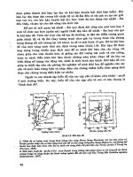
The electro-polishing system is shown in Fig. 1. The important parameters are as follows:
1. Substrate clean by acid-washing in H
2
O
2
:H
2
SO
4
=1:3 solution.
2. Electrolyte solution (Na
2
SO
4
) with concentration of 60-100 (g/L).
3. Current density in electro-polishing (EP) process is 0.1-1.0 (A/cm
2
).
The clamp was used to hold the anode and cathode plates. The anode and cathode plates
were separated by Teflon with thickness of 1 cm. Fig. 2 shows the optical microscopy (OM)
images of 304 SS substrate with and without EP process. The average surface roughness (Ra)
of 304 SS substrate increased from 0.045 μm to 0.197 μm after the EP process with current
density of 1A/cm
2
in 10 min.
陽極 陰極
Na
2
SO
4
電解液
Fig. 1. Experimental set-up of the EP process.
Cathode
Anode
Na
2
SO
4
electrolyte
Anode clamp area
Reaction area
Enhanced Diffuse Reflection of Light by
Using a Periodically Textured Stainless Steel Substrate
41
2.2 Sand blasting process
The glass sand (#320) was used to form randomly textured surface with cave size of several
μm to tens μm on the surface of stainless steel substrate. The average surface roughness (Ra)
of 304 SS substrate increased from 0.277 μm to 6.535 μm after the sand blasting process. The
OM images of raw 304 SS substrate and with sand blasting process were shown in Fig. 3.
Fig. 2. The OM images (x2000) of (a) raw 304 SS substrate surface and (b) 304 SS substrate
surface with EP process.
Fig. 3. The OM images (x400) of (a) raw 304 SS substrate surface and (b) 304 SS substrate
surface with sand blasting process.
2.3 Photolithography process
The photo-mask patterns were designed by CAD. Photolithography is a process of using
light to transfer a geometric pattern from a photo-mask to a photo-resist on a 430BA SS
substrate. The steps involved in the photolithographic process are metal cleaning, barrier
layer formation, photo-resist application, soft baking, mask alignment, exposure and
development, and hard-baking. After the photolithographic process, the 430BA SS substrate
is etched by aqua regia (HNO
3
: HCl=1 : 3). There are two types of photo-mask patterns:
one, different diameters but with the same interval, and two, the same diameters but with a
different interval. They are both designed to study light trapping for the application of thin
film solar cells. Finally, silver coating technique by e-beam evaporation was used to improve
the TR and DR rates of the 430BA SS substrate.
(a) (b)
(a) (b)
Solar Cells – Thin-Film Technologies
42
2.4 Lift-off and etching process
In this study, lift-off and etching processes were used to fabricate the different textures of
the 304BA SS substrates. The striped texture was created on the 304BA SS substrate using
the lift-off process. After the hard-baking process, a silver (Ag) thin film was deposited on
the substrate by e-beam evaporation. An acetone solution was used to remove the residual
photo resistor (PR). The depth of the striped texture was controlled by the thickness of the
Ag thin film deposited. Four different striped textures were created on the 304BA SS
substrates, including period/height: 6/0.1, 6/0.3, 12/0.1 and 12/0.3 μm. Two other types of
textured 304BA SS substrate, the ridged-stripe and pyramid texture with 22.5 μm width
were created by the etching process. After hard-baking, the 304BA SS substrate was etched
by aqua regia (HNO
3
: HCl : DI water=1 : 3 : 4). The etching temperature was 28-35℃ with
an etching time of 7-12 min. to control the etching depth of the textured 304BA SS substrate.
The detail experimental flow charts of lift-off and etching processes are shown in Fig. 4 and
Fig. 5, respectively.
3. Optical properties of textured stainless steel substrate
3.1 Measurements of optical properties of textured stainless steel substrate
The total reflection (TR) and diffuse reflection (DR) rates of incident light from the textured
substrate were carefully studied by using a Perkin Elmer Lambda 750S spectrometer. It was
known that the specula reflection takes place on a smooth surface, and the angle of reflection is
the same as the angle of incidence. DR is a phenomenon where an incident beam of light
strikes an uneven or granular surface and then scatters in all directions. In Fig. 6, the 6 cm
Fig. 4. The experimental flow charts of lift-off process.
1. Substrate cleaning
2. Coating PR
3. Softbake & exposin
g
UV li
g
ht
mask
4. Development
A
g
film
5. Hardbake & metal
deposition
6. Removing PR
7. Metal deposition
AZ4620
Aceton
Developer
SS 304BA
A
g
film
Enhanced Diffuse Reflection of Light by
Using a Periodically Textured Stainless Steel Substrate
43
Integrating Sphere is used for diffuse reflectance measurements. Reflectance measurements
include total and diffuse reflectance at an incident angle of 8 degrees. Specular reflectance
can be calculated from the total and diffuse reflectance measurements. The TR and DR rate
of a textured substrate are important indexes when increasing the light trapping efficiency
of thin-films solar cells.
Fig. 5. The experimental flow charts of etching process.
Fig. 6. The total reflection and diffuse reflection measured by integrating Sphere.