Electric Vehicles The Benefits and Barriers Part 7 potx
Bạn đang xem bản rút gọn của tài liệu. Xem và tải ngay bản đầy đủ của tài liệu tại đây (1.65 MB, 20 trang )
Fuel Cell Hybrid Electric Vehicles
109
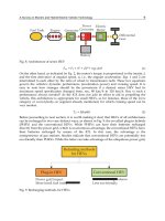
In order to demonstrate that fuel cell technology can be used also in farm sector “Hy-
Tractor” project wants to develop a fuel cell tractor fed by hydrogen. In farm sector the
hydrogen distribution is not a problem because hydrogen can be produced on site
using the available renewable energies: wind, photovoltaic, biomass. The main activities
are:
- Development of a hydrogen production and storage system based on: 1) photovoltaic
and electrolyzer (fig. 14), 2) biomass, 3) low temperature thermolysis, 4)
high
temperature pyrolysis;
- Design and development of tractor equipped with fuel cell powertrain, on board
hydrogen storage system and other needed auxiliary subsystems.
- Development of energy saving systems for efficiency increase. Some of these are:
photovoltaic roof, high efficiency air-conditioning and external lights, hydraulic
systems and power take-off (PTO) with electric drive.
- Replacement of hydraulic drive with electric drive, avoiding oil (that is a polluting
substances) and increasing the check.
- Design of a Multi-Power Testing-Trailer able to carry out simultaneous tests on the
traction, hydraulic system and electric devices.
- Field test of the FC tractor during operation both in external sites and inside places
(hayloft).
Fig. 20. “Hy-Tractor”: Project layout with photovoltaic plant.
The H-BUS is a joint project of National research Council of Italy and two supplier
companies to develop a range extender Fuel Cell/Battery Hybrid Electric city bus. The aim
of H-BUS project is to realize a pre-commercial Fuel Cell/Battery HEV able to increase the
range (at least 30%) with respect to same bus in a standard electric configuration, using a
small size of fuel cell that works as batteries recharge on board. Within the project, CNR
TAE Institute is involved in determining the optimal level of hybridization assessing all
boundary conditions (mission, performances, hydrogen consumption, range, etc ). The bus
selected for the prototype realization is an electric vehicle having an 85 kW rated power of
electric drive motor and a capacity of 44 passengers (Fig.21).
Electric Vehicles – The Benefits and Barriers
110
Fig. 21. The selected bus for the H-BUS project
5.1 Fuel cell systems development
The CNR ITAE collaborations with fuel cell developers are focused on improving
durability, architecture and cost reduction of fuel cell systems and stacks. As above said, in
automotive sector, PEMFC and SOFC are the principal technologies studied. The
development of PEM fuel cell systems is summarized in table 5, all devises are fed by pure
hydrogen. Gen 3 is a hybrid system composed by a stack of 5 kWe and a battery pack with a
power output of 4 kW. Besides, this system is equipped with a new kind of hydrogen
recirculation system which increases stack durability up to 10000 hr.
A fuel cell system is composed by fuel cell stack and the linked ancillaries: a blower for the
air, a pump for the water and a fan for the cooling circuit (Fig 22). Dedicated micro–
computer and software are used for the management of the entire system in terms of
operation and safety
The stack is the core componentof a fuel cell system but, for the electrical energy production,
hydrogen and air have to be fed into the stack. Excess heat must be removed through a
cooling system. The operational characteristic curve of a stack (polarization curve) illustrates
the device’s performance unambiguously. The experimental curve of the fuel cell PEM
system is is shown in Fig. 23a.It demonstrates that the stack works in a defined range of
voltage of 0.65-1Vcell. In this range of voltage it is possible to obtain high performance in
terms of efficiency and to limit the materials stress in order to assure a long durability. The
figure also reports cell voltage of stack (average voltage of two contiguous cells) at different
power levels (fig.23b). The stack is composed by 40 cells.
An important issue in automotive sector is the response time of system. For this reason start-
up/warm-up times have been evaluated at different temperatures in order to determine
system limitations and the best operative conditions. The aim was to minimize the battery
pack that supply the load and the FC system ancillaries at the same time. The first remark is
that batteries cannot be completely eliminated, due to start-up operations. In fact, during the
Fuel Cell Hybrid Electric Vehicles
111
Rated Power
(kW)
5 5 5 kW FC + 4 kW batteries
Number of
cells
40 40 40
Temperature
(°C)
80 80 80
Active area
(cm
2
)
500 500 500
Efficiency
(%)
52 54 54
Durability
(hr)
1500 3000 10000
Table 5. PEM Fuel Cell Systems development.
Fig. 22. Schematic diagram of the Fuel Cells System.
start-up, system drains an average current of 13.5 A (P = 648W), from an external power
supply (Fig. 18). The minimum time needed by the FC system to generate power is ever 7
seconds (FC system software setting), but its value never reaches the maximum value (5
kW) before the warm-up.
Ge
n
1 2006
Gen 2 2008
Gen 3 2009
Electric Vehicles – The Benefits and Barriers
112
Fig. 23. Polarization curve (A) and voltage distribution (B) for a stack of 40 cells PEM.
Fig. 24. Current demand from external 48V power supply by FC system during then start-
up.
0.00
0.20
0.40
0.60
0.80
1.00
1.20
1.40
1.60
1.80
1 2 3 4 5 6 7 8 9 10 11 12 13 14 15 16 17 18 19 20
Pair of cells
Cells Voltage [V]
4.8 kW 4.3 kW 3.8 kW 3.4 kW 2.8 kW
A
B
Fuel Cell Hybrid Electric Vehicles
113
The minimum time needed by the FC system to generate power is ever 7 seconds (FC
system software setting), but its value never reaches the maximum value (5 kW) before the
warm-up. FC system produces the best response when it starts to run at the nominal
temperature as shown in the following figure 19, where is reported the start-up/warm-up
time depending on the different initial FC system temperature. At the nominal temperature,
FC system generates maximum power after 76 seconds during start-up routine runs (7
seconds) and FC stack is warmed-up (69 seconds) at the nominal temperature.
Fig. 25. Start-up times at different initial FC system temperatures.
Rated Power
(kW)
1.248 1.811 1.096
Number of
cells
75 10 32
Temperature
(°C)
650 500 750
Active area
(cm2)
92 360 50
NG
reforming
Internal with pre-
reforming
Internal Internal
Table 6. Features of the three SOFC stacks.
Among Fuel Cells, SOFCs show the great advantage of working with more flexible gas than
than polymer electrolyte fuel cells. The table 6 reports the performance of three intermediate
Electric Vehicles – The Benefits and Barriers
114
temperature SOFC stacks. The aim is to build a complete SOFC power generation system
around the stack. All these three stacks have planar bipolar plate, but they are arranged with
different technical solutions: active areas, volumes, dimensions, ect.
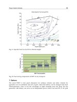
A polarization curve of a SOFC system tested is showed in figure 26. The stack power
output is 500 W and 55% of electric efficiency is expected. The working temperature is about
750 °C.
Polarizzazione "Asterix" 500kWe
15
20
25
30
35
40
45
02468101214161820
Corrente [A]
Tensione [V]
0
100
200
300
400
500
600
Potenza [W]
V_stack P_stack
Fig. 26. Polarization curve of a SOFC system with a power of 500 W.
These systems are suitable for small recreation vehicles (i.e. motor cycles, golf car), utility
vehicles ( i.e. fork-lift trucks) and hybrid vehicles in range extended configuration.
5.2 Hybrid powertrain studies
Over the years, CNR ITAE has evaluated different powertrain configurations in terms of
the energy flows and system components size. Here are reported some architectures chosen
for hybrid powertrains used in small vehicles and buses.
The structure of a hybrid powertarin for a golf car is the same showed in figure 16. The
hybrid powertrain is composed by the following main devices: fuel cell power soure, battery
pack, static power converter (inserted between FC and load diode between the static power
converter and load). The fuel cell system is a compact power module with a nominal power
of 5kWe, developed with Nuvera Fuel Cells. The lightweight vehicle was adequately
instrumented for data acquisition by applying speed transducer, voltage and current sensors
(fig. 27); it was subjected to a work cycle with heavy load conditions, both on road and in
laboratory simulated by electric load.
In this latter configuration, the fuel cell is used as main power source for the powertrain,
also providing battery charge. The battery has the role to provide peak power during the
start up of the vehicle and to supply the necessary energy to the fuel cell system during the
start up. The hybrid powertrain has shown a fast response even at extreme and impulsive
loads and a wider range compared to a battery vehicle, without compromising the weight
limitations on the vehicles.
The figure 28 shows the response of the battery and the fuel cell system during a rising
transient. The behaviour of starting batteries is characterized by a short delay in the load
response when rising transient begins. This phenomenon is due to a small power inlet from
Fuel Cell Hybrid Electric Vehicles
115
fuel cell to batteries. The batteries package is connected directly to the electronic load and, in
correspondence of the power demand, voltage decreases. As a consequence the recharging
current of the batteries increases, since the voltage difference between PowerFlow and
batteries is higher than the pre-fixed control value. During this very short time (0.1 s) the
fuel cell tries to recharge the batteries even if the demand is higher than its rated power.
This delay occurs every time the load changes. Moreover, the load response is slightly lower
than the electronic load demand.
Fig. 27. Golf car Hybrid Powertrain.
Fig. 28. Response of the battery and the fuel cell system during a rising transient.
An important instrument to identify the most favourable vehicle configuration in specified
operating conditions is the computer simulations. Figure 29 shows a power train simulation
for a bus in range extended configuration. A range-extender HEV is essentially an EV with
an on-board charging system(Suppes GJ et al., 2004). Simulation studies have been
performed to evaluate the potential SoC saving and autonomy increase with respect of pure
battery EV bus. The simulation models have been developed in the Matlab® Simulink®
environment utilizing the SimPowerSystems tool.
Electric Vehicles – The Benefits and Barriers
116
In the proposed configuration FC system works as batteries recharge that provides,
following an identified strategy, the necessary power to the driving cycle to increase the
autonomy of the vehicle. The storage system (traction batteries) provides, however, the
energy required to satisfy the peak power demand. PEM Fuel Cell and ZEBRA® (Zero
Emission Battery Research Activities) technologies have been selected for the fuel cell
system and batteries, respectively.
The study has demonstrated that a power train with 6 ZEBRA® batteries connected with 5
kW FC system appears as the best solution. This configuration allows to increase the range
of about 40% as shown Figure 30.
Fig. 29. Simulink® model of the powertrain for bus application.
Fig. 30. SoC (%) analysis: Comparison of proposed HEV (blue) and pure battery EV (green).
Fuel Cell Hybrid Electric Vehicles
117
The obtained results show that Fuel Cells and Batteries achieve an optimal synergy because
their combination provides better performance and lower costs than batteries or total fuel
cells vehicles.
With regard to the integration of fuel cell in the vehicles, the figure 31 shows the layout bus
for the project "H-Bus". The fuel cell system and hydrogen storage are assembled on the top
of the vehicle in substitution of N°1 batteries box. TIn order to reduce costs and improve the
fuel cell system technological development the exiting vehicle structure and electric drive
train technology have been used.
Batteries Pack N°1 Batteries Pack N°2
Batteries Pack N°3
Fig. 31. Position of batteries packs on the top of the electric Bus version (only battery electric
vehicle).
Fig. 32. Example of distribution of the power between SOFC and battery.
Some studies are focused on SOFC technology used mainly for APU demonstration units for
road vehicles having a hybrid configuration (Battery and FC). The work here reported
regards the integration of a little SOFC system of 500 W with a battery. In particular, a
specific control algorithm was developed for utilizing the SOFC system as a base power
source and battery as a complementary source (Fig.32). In fact, on the contrary of PEM
technology, SOFC device is not able to follow fast and wide changes of the load because its
Electric Vehicles – The Benefits and Barriers
118
high working temperature. The aim is to develop an efficient hybrid system able to deliver
the power requirement, to combine energy storage and to ensure durable operation.
To obtain benefits from the operation of a hybrid system, the flows of power within the
system must be carefully planned and regulated in accordance with an appropriate
energetic strategy to optimize the total efficiency and to preserve the devices from stress that
may reduce their lifecycle. This research with a power of 500 W can be scaled-up and
optimized for specific conditions.
6. References
World Resources Institute, Sustainable Development Information Service, The global
commons: Proceed with caution: Growth in the global motor vehicle fleet.
Ogden, J. M. (2005). Alternative fuels and prospects-Overview, In: Handbook of Fuel Cell.
Wolf Vielstich Arnold Lamm Hubert A. Gasteiger, 3-24, Wiley, England.
European Commission COM(2010)186 April 2010. A European strategy on clean and energy
efficient vehicles. Available from: < http://eur-
lex.europa.eu/LexUriServ/LexUriServ.do?uri=COM:2010:0186:FIN:EN:PDF>.
McKinsey & Company on behalf of a consortium of 31 public and private companies.
(November 2010). A Portfolio of Powertrains for Europe: A Fact Based Analysis: The role
of Battery Electric Vehicles, Plug-in Hybrids and Fuel Cell Electric Vehicles. Available
from :< www.zeroemissionvehicles.eu >
DOE, (January 2009). Hydrogen and Fuel Cell Activities, Progress, and Plans. Report to Congress.
Available from:
< >
DOE, (2010). Well-to-Wheels Greenhouse Gas Emissions and Petroleum Use for Mid-Size Light-
Duty Vehicles. Available from:
< www.hydrogen.energy.gov/program_records.html >.
Lisa Callaghan Jerram. 2008. 2008 Bus Survey, Available from
< >.
Gemma Crawley. (March, 2006). Proton Exchange Membrane (PEM) Fuel Cells, Available from
< >.
Gemma Crawley. (August, 2007). Direct Methanol Fuel Cells (DMFC). Available from
< >.
DOE (2010). Research and Development of Fuel Cells for Stationary and Transportation. Available
from: < www.energy.gov/>.
Lisa Callaghan Jerram (May, 2009). 2009 Light Duty Vehicle Survey. Available from
< >.
Dr. Jonathan Butler (2008). 2008 Niche Transport Volume 2. Available from
< >.
Gemma Crawley ( 2007). Solid Oxide Fuel Cells (SOFC). Available from
< >.
Fuel Cell 2000 (2011). Available from
<
Dr. Jonathan Butler (July 2008). 2008 Niche Transport Survey Vol.1. Available from
< >
Suppes GJ, Lopes S, Chiu CW (2004). “Plug-in fuel cell , hybridsas transition technology to
hydrogen infrastructure”. Int. J Hydrogen Energy Vol. 29, pp. (369-374).
7
Supercapacitors as a Power Source
in Electrical Vehicles
Zoran Stević and Mirjana Rajčić-Vujasinović
University of Belgrade, Technical faculty in Bor
Serbia
1. Introduction
Accelerated science and technology advances leads to improvement of human life, but also
creating of new crisis situation. Mankind is confronted with risks not seen earlier in human
history. Global worming is one of the typical examples. Although majority of the experts
studying climate changes claim global worming and fact that it is caused by human, there
are also scientists that doubt those statements. One of the main problems related to critical
situations is – mater of responsibility.
World Governments have to consult with experts and to estimate well when to announce
risk situation. Strong political initiative is needed to start dealing with serious ecological
problems as it is global worming. Political agreements at the world level which are achieved
so far under Kyoto protocol are not substantial enough to stop this phenomenon. According
to this protocol, gas emission that creates greenhouse effect should be reduced by eight
percent in first years of 20th century in European Union countries, seven percent in USA
and six percent in Japan. Even under assumption that all of signers of protocol follow the
agreement, global worming will continue till the moment of substantial reduction of gas
emission.
On the other hand, industrial giants as „General Electric“, „Toyota“ and „Sharp“ and
investment companies as „Goldman Sach“ are investing billions of dollars in clean
technologies. A clean technology development is not just social problem governed by people
dealing with environment protection, but it is also possible business that brings money and
slowly flows into business streams. In fact, economy is confronted with new challenges due
to very high energy prices, resource limits, global environment and security treats. That is
why clean technologies – technologies designed to provide superior performance at lower
price at same time creating less loses compared to conventional offerings – have great
chance to become future motor force providing economic growth.
Science, certainly, before all spots problems of planet survival and life on it. It also tries to
solve them and succeeds as much as it is possible in reality, having political, social,
economical and technological factors.
Electric drive vehicles present one of the most important technological advances having in
mind spread of this kind of nature pollution. Lately there is increased world interest for so
called hybrid vehicles that have reduced fuel consumption and much less pollutants
emission than regular vehicles. Hybrid vehicles can in broadest sense be described as
vehicles utilizing combination of production and storage of energy (Van Voorden at al.,
Electric Vehicles – The Benefits and Barriers
120
2007). Good properties of conventional vehicles are combined (long range and acceleration,
very good supply network) and electrical vehicles (zero emission, quiet operation,
regenerative use of braking energy).
Two kinds of these vehicles are in consideration - so called parallel and series hybrids. In
parallel hybrids there is a connection between power generator and driving wheels, while in
series that relation is not present. Series hybrids have substantial advantages compared to
parallels due to their mechanical simplicity, flexibility in terms of design and ability of
simple new technologies incorporation (Stević at al., 2002).
In next five years electrical and hybrid vehicles may became real alternative to classical
vehicles in big cities, as shown by research done by consultant company „Mc Kinsey &
Company“. New York plans about 70.000 electrical vehicles in 2015 their number in new
registered vehicles of 16 percent. Paris is planning for 60.000 and Senghai 25.000 such
vehicles.
Research showed that it is not required to build network of charging stations to increase sale
of electrical vehicles, since users are ready to charge its vehicles batteries at home. As a next
step could be a possibility of supermarkets, parking stalls and restaurants to offer their
clients charging stations. Very good solution is exchange empty for charged accumulator
batteries at the specialized stations.
Important factor to bring political decisions is a public opinion as well. So it is very
important to raise global ecological awareness and wider public education in that sense.
Goal of this chapter is to bring closer to reader new drive technologies that are intended to
environment and nature protection in all.
2. Supercapacitors vs. accumulator batteries and fuel cells
Supercapacitors are relatively new type of capacitors distinguished by phenomenon of
electrochemical double-layer, diffusion and large effective area, which leads to extremely
large capacitance per unit of geometrical area (in order of multiple times compared to
conventional capacitors). They are taking place in the area in-between lead batteries and
conventional capacitors. In terms of specific energy (accumulated energy per mass unity
or volume) and in terms of specific power (power per mass unity or volume) they take
place in the area that covers the order of several magnitudes. Supercapacitors fulfill a very
wide area between accumulator batteries and conventional capacitors taking into account
specific energy and specific power (Conway, 1999). Batteries and fuel cells are typical
devices of small specific power, while conventional capacitors can have specific power
higher than 1MW/dm
3
, but at a very low specific energy. Electrochemical capacitors
improve batteries characteristics considering specific power or improve capacitors
characteristics considering specific energy in combination with them. In relation to other
capacitor types, supercapacitors offer much higher capacitance and specific energies, as
illustrated in Figure 1.
Accumulator batteries and low temperature fuel cells are typical devices with low specific
power, where conventional capacitors may have specific power over 1MW/dm
3
, but at very
low specific energy. Electrochemical capacitor can improve characteristics of batteries in
terms of specific power and improve properties of capacitors in terms of specific energy
when they are combined with them (Stević, 2001).
Supercapacitors, ultracapacitors (commercial denominations given originally by its
manufactures Nippon Electric Company, NEC, in Japan, and by Pinnacle Research Institute,
Supercapacitors as a Power Source in Electrical Vehicles
121
PRI, in USA) or electrochemical double-layer capacitor (EDLC, technical name) are devices
that can be used as energy storage systems, that have high energy and power densities, a
high efficiency, nearly 95% and a large life expectancy (Guerrero at al. 2009).
Fig. 1. Area diagram for various energy storage systems
Supercapacitors store charge in a similar way to conventional capacitors, but the charge
does not accumulate in two conductors, but in the interface between the surface of a
conductor and an electrolytic solution. Devices consist of two electrodes which allow a
potential to be applied across the cell, therefore they present two double-layers, one at each
electrode/electrolyte interface (Bugarinović at al., 2007). An ion-permeable separator is
placed between the electrodes in order to prevent electrical contact, but still allows ions
from the electrolyte to pass through. The electrodes are made with high effective surface
materials, such as porous carbon or carbon aerogel (Bugarinović at al., 2008). Two principal
technologies are used (Stević at al., 2010): aqueous (maximum voltage of 1.2 V and work
voltage of 0.9 V) and organic (voltage near 3 V but with a much higher series resistance).
The principal supercapacitor characteristic that makes it suitable for using in energy storage
systems (ESS), is the possibility of fast charge and discharge without lost of efficiency, for
thousands of cycles. This is because they store electrical energy directly. Supercapacitors can
recharge in a very short time having a great facility to supply high and frequent power
demand peaks (Kotz & Carlen, 2000).
Supercapacitor can be manufactured in any size because they do not need a dielectric, form
high capacitance supercondensators for hybrid vehicles, to small capacitance ones to be
used in low power applications such as wireless systems.
Electric Vehicles – The Benefits and Barriers
122
Data given in Table 1 clearly show supercapacitor characteristics that make those devices
adequate for purposes requiring great specific energy and great specific power combination
or long lifetime denoted by charging and discharging number of cycles In other words,
capacitors have retained classical capacitors positive property to achieve almost unlimited
charging and discharging number of cycles.
Characteristic Classical capacitor Supercapacitor Accumulator
Discharging time
s – ms
ms – weeks min - months
Charging time
s – ms
ms – minutes hours
Specific energy < 0,01 Wh/dm
3
0,5 – 5 Wh/dm
3
< 500 Wh/dm
3
Specific power > 10
4
W/dm
3
(1-3) 10
3
W/dm
3
< 500 W/dm
3
Cycles number 10
6
- 10
8
(unlimited) 10
6
- 10
8
200 - 1000
Table 1. Capacitor, supercapacitor and accumulator basic characteristics
Literature offers data on two basic kinds of supercapacitors with different ways for energy
storing (Arbizzani at al., 2001). New trends in electrochemical supercapacitors. Journal of
Power Sources, Vol.100, No1-2, (November 2001):
a. double layer capacitors
b. redox supercapacitors.
Capacitance of the first kind is electrostatic by its nature, taking into account that distance
between quasi electrodes is extremely short, and electrode material has highly developed
surface. Typical examples are Faraday inactive coal powders including both assumptions.
The name electrochemical double layer capacitor describes the elementary principle of
energy storing at those devices. Principally, energy storing at double layer capacitor is a
result of electrical charge separation at the interface between electrode as electronic
conductor and electrolyte as ionic conductor. Capacitance created at that interface is the
double layer capacitance. Owing to the large specific area, coal is one of the best examples of
materials for double layer capacitors (Stević & Rajčić-Vujasinović, 2006). Electrochemical
processes taking place on double layer capacitors can be described in the following way
(Zheng at al. 1997):
Positive electrode:
Charging
E
s
+ A
-
Es
+
// A
-
+ e
-
Discharging
Negative electrode:
Charging
E
s
+ C
+
+ e
-
E // C
Discharging
Overall reaction:
Supercapacitors as a Power Source in Electrical Vehicles
123
Charging
E
s
+ E
s
+ C
+
A
-
E // A + E //C
Discharging
where E
s
represents carbon electrode surface, // presents the double layer in where charges
are accumulated on the two sides of the double layer, while C
+
and A
-
represent the cation
and the anion of the electrolyte. From above given equations it can be concluded that during
the charge electrons are forward from the positive electrode to the negative electrode
through an external power source, while positive and negative ions are separated from the
bulk electrolyte and moved to the electrode surfaces. During the discharge, electrons move
from the negative electrode to the positive electrode through the load, and ions are released
from the electrode surface and moved back into the bulk of the electrolyte. As it can be seen
from overall reaction, the salt (C
+
A
-
) in the electrolyte is consumed during charge, so the
electrolyte could be considered as an active material. During the charge and discharge, the
charge density at the interface electrode– electrolyte changes as well as concentration and
electrolyte conductivity (Stević at al., 2002).
Figure 2 presents the scheme of a symmetrical double layer elemental cell as well as
illustration of interface on which electrochemical double layer and potential drop appear
(Rajčić-Vujasinović at al., 1999).
a) b)
Fig. 2. (a) Cross section through a practical electrochemical double layer capacitor and
profiles of the potential across an electrochemical capacitor; (b) Simplified equivalent electric
circuit for an electrode – electrolyte interface
In the case of redox capacitors, in the course of electricity pass, Faraday processes are
occurring as at batteries and a new phenomenon, called pseudocapacitance is appearing
(Ardizzone at al., 1990). That is the reason why this kind of supercapacitors has got the
name pseudocapacitors. Typical representatives of the supercapacitors type are RuO
2
,
Co
3
O
4
, NiO
2
and IrO
2
in acid water solutions. Investigation of materials by cyclic
voltammetry method showed extremely capacitance behavior that can be explained only by
double layer capacitance. The latest researches in this field are focused to the development
of supercapacitors based at fast reversible Faraday reactions. Specific capacitances realized
at those supercapacitors are from 50 to 64 F/g, specific energy from 25 to 40 kJ/kg and
specific power 4 to 17 kW/kg.
Pseudocapacitors have rather greater values of specific energy comparing to carbon double
layer capacitors. Besides, electrical conductivity of metal oxide (RuO
2
) is extremely higher
Electric Vehicles – The Benefits and Barriers
124
than at carbons and all together lead to greater specific power or, in other words, to less RC
(resistance – capacitance) value of time constant. These pseudocapacitors advantages are
decreased by their high price compared to carbon. However, advantages realized with
carbon materials can be combined with advantages achieved with transient metals oxides,
so it led to the new class of electrochemical capacitors. Development of combined double
layer Faraday pseudocapacitors as a result may have the use of the advantages of metal
oxide Faraday capacitance and carbon material double layer capacitance (Miller at al. 1997).
Investigations of behavior of copper sulphide minerals during their anodic polarization and
modeling of these reactions were performed at Bor Technical faculty. On this occasion, it
was established that equivalent electrical circuit must contain very high capacitances,
indicating possibility of copper sulphide mineral use as potential material for
electrochemical supercapacitor electrodes (Stević at al., 2003).
3. Supercapacitor characterization
Electrochemical investigation methods are widely used for characterization of different
kinds of materials, as well as of the processes in systems where the electrochemical reactions
take part. There is a series of well known methods, but some new methods from
electrotechnical area have been introduced (Stević at al., 2008). So, first of all it was given an
overview of the standard electrochemical methods and parameters, beginning with
potential measurement and simple methods such as chronopotentiometry and
chronoamperometry, till electrochemical impedance spectroscopy (Stević at al., 2010). The
last named method is adapted for systems containing large capacitances that became
actually with appearance of electrochemical supercapacitors. New methods are Dirac
voltage excitation and Dirac current excitation. Measurement system described here allows
application of electrochemical methods, as follows: measuring open circuit potential,
chronopotentiometry, chronoamperometry, galvanostatic method, potentiostatic method,
Dirac voltage excitation, galvanodynamic method, cyclic voltammetry and electrochemical
impedance spectroscopy.
For signal generation and data acquisition it was developed a measuring and control system
based on PC Pentium 4. Beside PC, hardware consists of ADDA converter and external
interface for analog signals conditioning. ADDA conversion is performed using
commercially available converter NI 6251 from National Instruments, M series high-speed
multifunction data acquisition. They have an onboard NI-PGIA2 amplifier designed for fast
settling times and high scanning rates, ensuring 16-bit accuracy even when measuring all
channels at maximum speeds.
Measurement interface has been designed for the needs of the electrochemical investigations
by controlled current or voltage excitation and response registration.
The software platform for predicted measurement methods was National Instruments Lab
VIEW package, which is regarded as a high standard in the area of modern virtual
instruments. In Lab VIEW, one builds a user interface by using a set of tools and objects. The
user interface is known as the front panel. As an example, the description, as well as Front
Panel has been showed for the Electrochemical Impedance Spectroscopy (Stević at al., 2004).
3.1 Electrochemical impedance spectroscopy
In this method differs, before any measurement has been done, on the outlet there has been
put the direct (DC) voltage to last long enough in order to achieve a stationary regime, and
Supercapacitors as a Power Source in Electrical Vehicles
125
then the current measurement can be started as a response to a complex excitation
(superimposed alternating voltage of an order of magnitude milivolts on DC level up to
10V). The assigned parameters are: open circuit potential, E
oc
, direct voltage, E
DC
, and time
of the regime duration, to (Stević at al., 2009).
Fig. 3. Front panel of the measuring system for electrochemical impedance spectroscopy
Fig. 4. Electrochemical impedance spectroscopy diagram
Electric Vehicles – The Benefits and Barriers
126
After the DC regime expires, the initial WHILE loop starts, in which the current value of the
alternate voltage of the assigned amplitude EmAC and the calculated frequencies (block
DAQmx Write), the channel (AOCH1) have been generated. The frequency is calculated in
the external loop according to octaves, in relation to the assigned values starting from fmin
to fmax. The lowest frequency can be 1µHz necessary for systems with high capacitances.
The generated alternating voltage is being superimposed with already installed DC voltage
and they both make together the excitement of the electrochemical system.
The current response, which in the pseudo stationary regime has also got the sinusoidal
shape with a DC component, is measured on the analog input channel, being averaged,
converted into an array and led in a block Array Max&Min. On the base of this block it is
possible to calculate the average maximal value of the superimposed component of the
voltage excitation so that the outcome is the module of system impedance which is
memorized and graphically displayed as a function of the logarithm of the frequency – Bode
diagram of an impedance (Fig.3 and 4).
4. Supercapacitor applications
Considering applying, there are four groups of supercapacitors. Depending on applying
place, different characteristics of supercapacitors can be more or less taken into account.
Some of them are of crucial importance for capacitor choice, and some of them can be of no
importance at all. The most important catalogue data for different commercial
supercapacitor types are given in Table 2.
First group includes capacitors for supplying electronic consumers of small power and very
low voltage (CMOS memories, watches, micro controllers, intelligent sensors etc.). They are
most frequently produced as a miniature cell of great capacitance. Crucial role at choice
have cell voltage, capacitance and self-discharging current. Inner (linear) resistance is
resistance of less importance.
Second group includes filter capacitors for obtaining “ideally” filtered one-way voltages.
Apart from great capacitance, cell voltage is of great importance for them, and for achieving
working voltage, it most frequently requires linear connection of several cells. Self-
discharging current and linear resistance are practically of no importance.
Third group of supercapacitors in future will have great application in energetic electronics
complexes of medium power, using for electrical energy reservoirs in transient regime.
There is an actual possibility to replace soon massive inductivities, which are at the same
time great sources of electromagnetic disturbances. Used for those purposes, supercapacitor
must have great capacitance and relatively great working voltage (implicating linear cell
connection and all problems related to that). Inner resistance has to be rather small, and
leakage current is not of greater importance.
Most strict requirements are related to capacitors of fourth group applying in electric
haulage, i.e. for vehicles of the future. Nowadays, batteries of several hundreds farad
capacitance are with working voltage of several hundred volts have been produced. Beside
great capacitance and relatively high working voltage, these capacitors must have great
specific energy and power (because of limited space in vehicle). Considering their specific
power, they have great advantage in relation to accumulator batteries, but, on the other side,
they are incomparably weaker considering specific energy. Hence, ideal combination is
parallel connection of accumulator and condenser batteries. In an established regime
Supercapacitors as a Power Source in Electrical Vehicles
127
(normal drawing) vehicle engine is supplied from accu-battery, and in the case of rapidly
speeding, from supercapacitor. Very important is the fact that in the case of abrupt breaking,
complete mechanical energy could be taken back to system by converting into electrical
energy only in presence of supercapacitor with great specific power. Because of mentioned
reasons, inner resistance of these supercapacitors has to be extremely small. Leakage current
is not of essential importance. Vehicles with such drive are not still in wide use, and the
reasons for that are for sure economic.
Parameter / Model Pulse fast supercapacitors Supercapacitors for applying:
Continually Reserve
Dimensions, mm 55 x 35 x 4 27 x 17 x 2,0
24 / h5 21 / h15
Nominal voltage,
V
4,5 4,5 3,6 5,5 3,6 5,5
Nominal
capacitance, mF
200 – 400 50 –80 1000 400 2400 1000
Leakage current,
A
< 50 < 20 < 3
- 25 do + 70
Working/storage
temperature,
o
C
- 20 do + 60
- 20 do + 60
Table 2. Some of the most important characteristics of different supercapacitor types
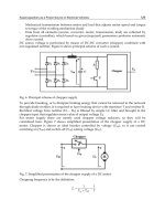
Fig. 5. Scheme of electrical drive vehicle with supercapacitor with possibitlity for using
breaking energy; B – one-way voltage source, SC – supercapacitor; DC/DC – direct voltage
converter; R – regulator; M-G – engine – generator (depending on working regime; W –
drive wheels
Vehicles with electrical drive would present one of the most significant ecological
advantages taking into account diffusion of this kind of nature pollution. There is an
increased interesting for so-called hybrid vehicles in the world lately, with less fuel
consumption and relatively less harmful product emission. Generally, hybrid vehicles could
be described as vehicles using combination of technologies for energy production and
Electric Vehicles – The Benefits and Barriers
128
storage. Two types of the vehicles are in consideration – so called parallel and linear
hybrids. Parallel type possesses mechanical connection between power generator and drive
wheels, while in linear one such connection does not exist. Serial hybrids have significant
advantages in relation to parallel ones because of their mechanical simplicity, design
flexibility and possibility for simple incorporation of new technologies.
In Figure 5 the scheme of an electrical drive vehicle in which supercapacitor is used for
energy storage and so-called regenerative breaking is presented.
Critical component at each hybrid or pure electrical vehicle presents electrical storage.
Supercapacitors are nowadays the only available technology, which can provide great
specific power (over 1 kW/kg) and great number of cycles at reasonable price and save and
reliable work. Supercapacitors have other characteristics that make them attractive in hybrid
vehicles such as possibility of complete energy using (so called regenerative breaking) for
increasing energy efficiency, with no additional maintenance, great recovery of electrical
energy, little toxicity and easy disposal after usage.
The greatest advance is expected at hybrid vehicles in city traffic. More variants of vehicle
prototypes are tested in real conditions in heavy traffic of the largest world cities. Data on
installed supercapacitors in a vehicle are given in Table 3.
Table 3. Data on installed supercapacitors in a vehicle
5. Supercapacitors in regulated electrical drives
Regulated electrical drives are nowadays 20-25% of all electric drives. They are developing
quickly and present to constructors stricter and stricter speed regulation (and position) and
torque. From energy point of view it is desirable their more participation, since optimal
speed setting or required can lead to reduction of used energy.
Typical regulated speed electrical drive is comprised of:
- converter located between source and motor that adjusts typical source values:
frequency, voltage, current, number fo phases to required by motor. Dosing this energy
also achives motor governing.