Biofuel''''s Engineering Process Technology Part 3 potx
Bạn đang xem bản rút gọn của tài liệu. Xem và tải ngay bản đầy đủ của tài liệu tại đây (2.76 MB, 40 trang )
Biogas Upgrading by Pressure Swing Adsorption
71
Another topic that is important for the selection of materials for the PSA process for biogas
upgrading, is the presence of contaminants. Apart from CH
4
and CO
2
, other gases present in
biogas are H
2
S and H
2
O. In almost all adsorbents, H
2
S is irreversibly adsorbed, reason why
it has to be removed before the PSA process. When carbonaceous materials are employed it
is possible to remove H
2
O in the same vessel as CO
2
. However, that is not possible using
zeolites since water adsorption is also very steep, resulting in a very difficult desorption.
0
0.4
0.8
1.2
1.6
2
012345
Amount adsorbed [mol/kg]
Pressure [bar]
T = 298 K
T = 308 K
T = 323 K
CH
4
0
1
2
3
4
5
6
012345
Amount adsorbed [mol/kg]
Pressure [bar]
T = 298 K
T = 308 K
T = 323 K
CO
2
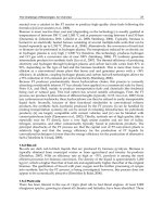
Fig. 3. Adsorption equilibrium of CO
2
(a) and CH
4
(b) on zeolite 13X at 298, 308 and 323 K
(Data from Cavenati et al., 2004).
3.2 Packed-bed performance
Adsorption is a spontaneous process and when the gas is putted in contact with the
adsorbent, a new equilibrium state will be established, depending on the partial pressure of
each of the gases and on the total temperature of the system. After achieving such
equilibrium, no more adsorption takes place and the adsorbent should be regenerated. For
this reason, a PSA column should be regenerated periodically to be able to absorb CO
2
in
different cycles. In order to keep constant feed processing, more than one column are
employed in parallel: when biogas is fed for selective removal of CO
2
, the other column(s)
are being regenerated.
The operation of a PSA process for biogas upgrading can be explained by showing what
happens when a mixture of CH
4
-CO
2
is fed to a column filled with adsorbent. For simplicity,
the column will be considered to be at the same pressure of the biogas stream and filled
with an inert gas (helium). An example of such behaviour is normally termed as
“breakthrough experiments”. An example of a breakthrough curve of CH
4
(55%) - CO
2
(45%) mixture in CMS-3K is shown in Figure 4 (Cavenati et al., 2005). It can be observed that
in the initial moments, methane molecules travel across the column filling the gas phase in
the inter-particle space, but also in the intra-particle voids (macropores), replacing helium.
Due to the very large resistance to diffuse into the micropores, CH
4
adsorption is very
difficult, reason why it breaks through the column very fast. On the other side, CO
2
takes a
very long time to break through the column since it is being continuously adsorbed. Note
that before CO
2
breakthrough, there is a period of time where only methane is obtained at
the column product end. In Figure 4(b) also the temperature increase on the different
positions of the column is shown. Note that in this experiment, temperature increase is due
(a)
(b)
Biofuel's Engineering Process Technology
72
solely to CO
2
adsorption. This experiment was carried out under non-isothermal and non-
adiabatic conditions. In the case of larger adsorbers where adiabatic conditions can be
found, temperature increase should be higher having a stronger negative impact in the
adsorption of CO
2
(faster breakthrough).
Another important thing that can be observed in Figure 4 is the dispersion of the CO
2
curve.
The perturbation in the feed stream was a step increase in CH
4
and CO
2
partial pressure and
the breakthrough result indicates that the response to that input after passing through the
column is quite spread. The shape of the adsorption breakthrough curves is associated to
diverse factors:
1. Slope of the adsorption isotherms: comprise the concentration wave if isotherm is
favourable (Langmuir Type) and dispersive if the adsorption equilibrium is
unfavourable (desorption for Langmuir-type isotherms). No effect if the isotherm is
linear,
2. Axial dispersion of the adsorption column: disperse the concentration wave,
3. Resistance to diffusion within the porous structure of the adsorbent: disperse the
concentration wave.
4. Thermal effects: normally in gas separations the thermal wave travels at the same
velocity as the concentration wave (Yang, 1987; Ruthven et al., 1994; Basmadjian, 1997)
and its effect is to disperse the concentration wave. Thermal effects can control the
shape of the breakthrough curve.
0
0.1
0.2
0.3
0.4
0.5
0 500 1000 1500 2000 2500 3000
Molar flow [mmol/s]
Time [seconds]
CH4
CO2
300
305
310
315
320
325
330
0 500 1000 1500 2000 2500 3000
Temperature [K]
Time [seconds]
0.17m
0.43m
0.68m
Fig. 4. Binary CH
4
(55%) – CO
2
(45%) breakthrough curve experiment in fixed-bed filled
with CMS-3K extrudates. Temperature: 303 K; Pressure: 4 bar (data from Cavenati et al.,
2004). (a): molar flow of CH
4
and CO
2
; (b) temperature evolution in three different points of
the column.
To compare the performance of different adsorbents, the thermal effects associated to
adsorption of CO
2
in zeolite 13X extrudates can be observed in Figure 5 where a
breakthrough of CO
2
was carried out (Cavenati et al., 2006). The experiment was conducted
at 299 K and a total pressure of 3.2 bar. It can be observed that CO
2
breaks through the bed
quite sharply due to the strong non-linearity of the CO
2
adsorption isotherm that tends to
compress the concentration front. After the initial sharp breakthrough, the shape of the
curve gets quite dispersed due to thermal effects. It can be seen in Figure 5(b) that the
temperature increase in certain points of the column is quite high, reducing the loading of
CO
2
and making breakthrough quite faster than it should be if carried out at isothermal
conditions. The opposite effect will take place in desorption of CO
2
: the temperature in the
(a)
(b)
Biogas Upgrading by Pressure Swing Adsorption
73
bed will drop increasing the steepness of the adsorption isotherm, making desorption more
unfavourable.
Fig. 5. Breakthrough curve of pure CO
2
in fixed-bed filled with zeolite 13X extrudates.
Temperature: 299 K; Pressure: 3.2 bar (data from Cavenati et al., 2006). (a): molar flow of
CO
2
; (b) temperature evolution in three different points of the column.
Due to the thermal effects and the steepness of the CO
2
isotherm on zeolite 13X, it was
concluded that using a similar PSA cycle, if the temperature of the biogas stream is close to
ambient temperature, it is better to use the Carbon Molecular Sieve (CMS-3K) than zeolite
13X (Grande and Rodrigues, 2007).
The solid lines shown in Figures 4 and 5, represent the prediction of a mathematical model,
based on pure gas adsorption equilibrium and kinetics (Cavenati et al., 2004; Cavenati et al.,
2005). The resulting equations for the prediction of the fixed-bed behaviour are (Da Silva,
1999):
i. mass balances in the column, particle and micropores (crystals) of the adsorbent.
ii. Energy balances in the gas and solid phases and column wall
iii. Momentum balance (simplified to the Ergun equation)
iv. Multicomponent adsorption isotherm model.
Note that the mass, energy and momentum balances are partial differential equations linked
by a (generally) non-linear equation (isotherm model). The mathematical model was tested
under diverse adsorbents and operating conditions for CH
4
-CO
2
separation as well as for
other gas mixtures. The mathematical model employed is termed as “homogeneous model”
since it considers mass and heat transfer in different phases using different equations.
Heterogeneous models (single energy balance) and also more simplified mass transfer
models can also be employed to predict column behaviour with good accuracy (Ruthven,
1984; Yang, 1987; Ruthven et al., 1994).
3.3 Packed-bed regeneration: basic cycles
Once that the adsorbent is selected to perform a given CH
4
-CO
2
separation under specific
operating conditions (T, P, y
CO2
), there are only few actions that can be taken to make the
adsorption step more efficient (dealing with energy transfer, for example). When designing
the upgrading PSA, the most important task is to make desorption efficiently.
The initial work reporting Pressure Swing Adsorption technology was signed by Charles W.
Skarstrom in 1960 (Skarstrom, 1960). A similar cycle was developed by Guerin - Domine in
Temperature [K]
CO
2
flow [mmol/s]
Time [seconds] Time [seconds]
Biofuel's Engineering Process Technology
74
1964 (Guerin and Domine, 1964). The Skarstrom cycle is normally employed as a reference
to establish the feasibility of the PSA application to separate a given mixture.
The Skarstrom cycle is constituted by the following cyclic steps:
1. Feed: the CH
4
-CO
2
mixture is fed to the fixed bed where the adsorbent is placed.
Selective adsorption of CO
2
takes place obtaining purified CH
4
at the column product
end at high pressure.
2. Blowdown: immediately before CO
2
breaks through, the column should be regenerated.
This is done by stopping the feed step and reducing the pressure of the column counter-
currently to the feed step. Ideally, this step should be carried out until a new
equilibrium state is established as shown in Figure 1. However, the blowdown step is
stopped when the flowrate of CO
2
-rich stream exiting the column is small. With the
reduction of pressure, CO
2
is partially desorbed from the adsorbent. In this step, the
lowest pressure of the system is achieved.
3. Purge: when the low pressure is achieved, the column will have CO
2
molecules in the
adsorbed phase but also in the gas phase. In order to reduce the amount of CO
2
in both
phases, a purge step is performed counter-current to feed step. In the purge, some of
the purified methane is recycled (light recycle) to displace CO
2
from the CH
4
product
end.
4. Pressurization: Since the purge is also performed at low pressure, in order to restart a
new cycle, the pressure should be increased. Pressurization can be carried out co-
currently with the feed stream of counter-currently with purified CH
4
. The selection of
the pressurization strategy is not trivial and may lead to very different results (Ahn et
al., 1999).
CH
4
CO
2
Feed
Internal recycle
Fig. 6. Schematic representation of the different steps in a Skarstrom cycle. The dotted line
represents the external boundary used to calculate performance parameters.
Biogas Upgrading by Pressure Swing Adsorption
75
A schematic representation of the different steps of one column in a single cycle is shown in
Figure 6. Note that in this image an external boundary was established. This boundary is
used to define the performance parameters of the PSA unit: CH
4
purity, CH
4
recovery and
unit productivity. They are calculated using the following equations:
4
0
42
00
tfeed
CH
zL
tfeed tfeed
CH CO
zL zL
Cudt
PURITY
C u dt C u dt
(1)
44
00
44
0
00
tfeed tpurge
CH CH
zL zL
tfeed tpress
CH CH
zzL
C u dt C u dt
RECOVERY
C u dt C u dt
(2)
44
00
.
tfeed tpurge
CH CH col
zL zL
cycle ads
Cudt CudtA
PRODUCTIVITY
tw
(3)
where
C
CH4
is the concentration of methane, u is the velocity, t
cycle
is the total cycle time, A
col
is the column area and w
ads
is the total adsorbent weight. Note that the calculation of CH
4
recovery and unit productivity involves the molar flowrates of the different steps where
some CH
4
is recycled. In the case of changing the cycle configurations, the equations to
calculate the process parameters may also be different.
In the cycle developed by Guerin-Domine, a pressure equalization step between different
columns take place between feed and blowdown and after the purge and the pressurization.
The pressure equalization steps are very advantageous for PSA applications since they help
to improve the recovery of the light product, they reduce the amount of gas lost in the
blowdown step and as a direct consequence, the purity of the CO
2
-rich stream obtained in
the blowdown (and purge) steps increases and also less power is consumed if blowdown is
carried out under vacuum. It should be mentioned that in the PSA process for biogas
upgrading, it is important to perform some pressure equalization steps to reduce the
amount of methane that is lost in the blowdown step. The amount of CH
4
lost in the process
is termed as CH
4
slip and in PSA processes is around 3-12% (Pettersson and Wellinger,
2009). More advanced cycles for other applications also make extensive use of the
equalization steps: up to three pressure equalizations between different columns take place
in H
2
purification (Schell et al., 2009; Lopes et al., 2011). As an example, in Figure 7, the
pressure history over one cycle is shown for the case of a two-column PSA process using a
modified Skarstrom cycle with one pressure equalization step (Santos et al., 2011).
Continuing with the example of CMS-3K as selective adsorbent for biogas upgrading, the
cyclic performance of a Skarstrom cycle is shown in Figure 8. In this example, the feed was a
stream of CH
4
(55%) – CO
2
(45%) resembling a landfill gas (T = 306 K), with a feed pressure
of 3.2 bar. The blowdown pressure was established in 0.1 bar and pressurization step was
carried out co-current with feed stream (Cavenati et al., 2005). Figure 8(a) shows the
pressure history over one entire cycle while Figure 8(b) shows the molar flowrate of each
gas exiting the column. It can be seen that in the feed step, a purified stream of CH
4
is
obtained. In this experiment, the purity of CH
4
was 97.1% with a total recovery of 79.4%
Biofuel's Engineering Process Technology
76
(Cavenati et al., 2005). An important feature of the CMS-3K adsorbent is related to the very
slow adsorption kinetics of CH
4
. In Figure 8(c) the simulated amount of CH
4
adsorbed is
shown. It can be observed that after reaching the cyclic steady state (CSS), the loading of
CH
4
per cycle is constant: this means that no CH
4
is adsorbed in the column. This is very
important since no CH
4
will be adsorbed in the pressurization step, even with a very strong
increase in its partial pressure. Unfortunately, the narrow pores also make CO
2
adsorption
(and desorption) difficult, reason why only part of the capacity of the bed is employed as
shown in Figure 8(d) resulting in small unit productivity.
Product
4
Feed
Feed
Product
Pur
g
e
Pur
g
e
1 2 3 4 5 6
4 5 6 1 2 3
Fig. 7. Scheduling of a Skarstrom cycle in a two column PSA unit: (a) step arrangement: 1.
Pressurization; 2. Feed; 3. Depressurization; 4. Blowdown; 5. Purge; 6. Equalization. (b)
Pressure history of both columns during one cycle.
As can be seen, an important amount of CH
4
is lost in the blowdown step, since there is no
pressure equalization: pressure drops from 3.2 bar to 0.1 bar having at least 55% of CH
4
in
the gas phase. The main problem of using the Skarstrom cycle for biogas upgrading is that
the CH
4
slip is quite high. Since the Skarstrom cycle is potentially shorter than more
complex cycles, the unit productivity is higher. Keeping this in mind, it may be interesting
to employ this cycle in the case of combining the production of fuel (bio-CH
4
) and heat or
electricity where the gas obtained from the blowdown step can be directly burned or
blended with raw biogas.
In order to avoid large CH
4
slip, at least, one pressure equalization should be employed to
reduce the amount of methane in the gas phase that is lost in the blowdown stream. If such
step is performed, it is possible to increase the methane recovery from 79.4% to 86.3%
obtaining methane with a similar purity (97.1%). It can be concluded that the increase of
number of equalization steps will reduce the methane lost in the blowdown step.
Furthermore, if less gas is present in the column when the blowdown step starts, the
vacuum pump will consume less power. However, to perform multiple pressure
equalizations, the number of columns and the complexity of operation of the unit increase.
Furthermore, the time required by the multiple pressure equalization steps will reduce the
unit productivity resulting in larger units. A trade-off situation is normally achieved in PSA
units with four-columns employing up to two pressure equalization steps before blowdown
(Wellinger, 2009).
0
0.5
1
1.5
2
2.5
3
3.5
4
4.5
0 200 400 600 800
Time [s]
Pressure [Bar]
1 2 3
4
5 6
(a)
(b)
Biogas Upgrading by Pressure Swing Adsorption
77
Another source of CH
4
slip is the exit stream of the purge step: in the purge, part of the
purified CH
4
stream is recycled (counter-currently) to clean the remaining CO
2
in the
column. Since CH
4
is not adsorbed, after a short time it will break through the column.
However, if the purge step is too short, the performance of the PSA cycle is poor. In order to
achieve very small CH
4
slip keeping an efficient purge, one possible solution is to
recompress and recycle this stream (Dolan and Mitariten, 2003). Furthermore, if this stream
is recycled, the flowrate of the purge can be used to control the performance of the PSA
cycle when strong variations of the biogas stream take place (CO
2
content or total flowrate).
0
0.5
1
1.5
2
2.5
3
3.5
0 100 200 300 400
Pressure [bar]
Time [seconds]
0
0.4
0.8
1.2
1.6
2
0 100 200 300
Molar flow [mmol/s]
Time [seconds]
1
2
34
0
0.1
0.2
0.3
0.4
0.5
0.6
0 0.2 0.4 0.6 0.8
CH
4
adsorbed [mol/kg]
Column length [m]
4
2
1
3
0
0.2
0.4
0.6
0.8
1
1.2
1.4
1.6
0 0.2 0.4 0.6 0.8
CO
2
adsorbed [mol/kg]
Column length [m]
1
2
3
4
Fig. 8. PSA separation of a mixture of CH
4
(55%) – CO
2
(45%) using a packed bed filled with
CMS-3K operating with a Skarstrom cycle (1. Pressurization; 2. Feed; 3. Blowdown; 4.
Purge). Feed pressure: 3.2 bar; blowdown pressure: 0.1 bar. (a) Pressure history over one
cycle; (b) molar flowrate exiting the column; (c) loading of CH
4
at the end of each step;
loading of CO
2
at the end of each step. Data from Cavenati et al., 2005.
4. New markets and improvements of PSA technology
As mentioned before, the biogas market has enormous possibilities to grow. One of the most
important sectors that may trigger large growth of PSA development is within small farms.
In such cases, the biogas can be employed for heating and to generate electricity, but a
portion of the stream (or the exceeding) can be upgraded to fuel. In such applications,
besides the specifications of process performance, six characteristics are desired for any
upgrading technology:
(a)
(b)
(c)
(d)
Biofuel's Engineering Process Technology
78
1. Economic for small streams,
2. Compact,
3. Automated,
4. Minimal attendance (by non-expert person most of the time),
5. Possible to switch on /off quite fast
6. Deliver product specifications even when subjected to strong variations in feed.
The PSA technology can potentially be employed in such applications since it can satisfy
most of the criteria established above. As an example it can be mentioned that some plants
of the Molecular Gate technology are operated remotely (automated with minimal
attendance) transported in trucks (compact) and they are employed for small streams of
natural gas (Molecular Gate, 2011). However, the scale of small biogas application is quite
small (smaller than 10 m
3
/hour). Furthermore, fast switch on/off a PSA unit for several
times was not reported in literature and surely require dedicated research as well as PSA
design to handle strong variations in feed streams.
The two major areas where research should be conducted to deliver a PSA unit to tackle
such applications are: new adsorbents and design engineering.
4.1 New adsorbents
Despite of the explosion in discovery of new materials with a wide range of possibilities,
most of the PSA units existing in the market still use the well-known zeolites (4A, 5A and
13X), activated carbons, carbon molecular sieves, silica gel and alumina. Since the adsorbent
material is the most important choice for the design of the PSA unit, more efficient materials
should be employed to satisfy more market constrains (energy consumption and size). One
interesting example of the possibility of application of new materials is the Molecular Gate
technology, where the utilization of narrow pore titanosilicates (ETS-4) lead to a successful
technology for CH
4
upgrading (Kuznicki, 1990; Dolan and Mitariten, 2003). The ETS-4
materials when partially exchanged with alkali-earth metals present a unique property of
pore contraction when increasing the temperature of activation (Marathe et al., 2004;
Cavenati et al., 2009). This property is very important since the pores can be adjusted with a
very high precision to do separations as complex as CH
4
-N
2
. Within this kind of inorganic
substrates, other interesting material that deserves attention are the aluminophosphates.
Even when these materials do not present a very high CO
2
capacity, they have quite linear
isotherms (ideal for utilization in PSA applications) and also some of them present Type V
isotherms for water adsorption, which means that they have certain tolerance (and
regenerability) if traces of water are present (Liu et al., 2011).
In the last years, a new family of materials with extremely high surface area has been
discovered (Li et al., 1999; Wang et al., 2002; Millward and Yaghi, 2005; Mueller et al., 2005;
Kongshaug et al., 2007). The metal-organic frameworks (MOFs) can actually adsorb
extremely large amounts of CO
2
when compared with classical adsorbents. Furthermore, it
is possible to adjust the structure in such a way that the steepness of the isotherm is mild
and thus regeneration is simpler. An example of this high CO
2
loading on MOFs is given in
Figure 9 where the isotherms of CO
2
and CH
4
on Cu-BTC are shown at different
temperatures (Cavenati et al., 2008). Comparing these isotherms with the ones presented by
zeolite 13X (Figure 3), it can be observed that the steepness of the isotherm is quite mild
leading to much higher “cyclic capacity” than zeolite 13X. Several MOFs were studied to
separate CH
4
-CO
2
mixtures (Schubert et al., 2007; Cavenati et al., 2008; Llewellyn et al., 2008;
Dietzel et al., 2009; Boutin et al., 2010). Most of them present excellent properties for CO
2
Biogas Upgrading by Pressure Swing Adsorption
79
adsorption, eventually with mild-non-linearity of CO
2
isotherms. Issues to commercialize
these materials are related to the correct formulation and final shaping without significantly
loosing their surface area.
0
0.4
0.8
1.2
1.6
2
0 0.5 1 1.5 2 2.5 3
Amount adsorbed [mol/kg]
Pressure [bar]
T = 303K
T = 323K
T = 373K
0
1
2
3
4
5
6
7
8
0 0.5 1 1.5 2 2.5 3
Amount adsorbed [mol/kg]
Pressure [bar]
T = 303K
T = 323K
T = 373K
Fig. 9. Adsorption equilibrium of CO
2
(a) and CH
4
(b) on Cu-BTC MOF at 303, 323 and 373 K
(data from Cavenati et al., 2008).
The extremely high CO
2
loading of MOFs indicate that the size of the PSA unit can be
significantly reduced using this material instead of classical adsorbents. Furthermore, the
CO
2
adsorption kinetics in several MOFs is quite fast, thus most of its loading can actually
be employed per cycle. One of the main issues with MOFs is that water cannot be present in
the system and should be removed in a previous step (which should not be an important
problem since water must be removed anyway).
4.2 Alternative PSA design
A possible route to design a new PSA unit involve the selection of the adsorbent, the
selection of the PSA cycle that should be used, the sizing of the unit, the definition of
operating variables for efficient adsorbent regeneration and finally the arrangement of the
multi-column process for continuous operation (Knaebel and Reinhold, 2003). However, in
the development of new applications in small scale, other parameters can be considered,
particularly the ones related to the design of the unit. One example of the possibility of out-
of-the-box process design is the rotary valve employed by Xebec that has allowed the
industrial application of rapid-PSA units for biogas upgrading (Toreja et al., 2011). When
designing small units, the shape of the columns can be different to the traditional ones and
this fact can be used to maximize the ratio of adsorbent employed per unit volume.
Furthermore, in some cases of high CO
2
contents, the heat of adsorption may increase the
temperature of the adsorbent in such a way that the effective capacity decreases
significantly. In such cases, the possibility of effective heat exchange with the surroundings
can be an alternative (Bonnissel et al., 2001) as well as increase the heat capacity of the
column (Yang, 1987). Other alternative to increase the unit productivity when using kinetic
adsorbents (like CMS-3K) is to use a second layer of adsorbent with larger pores (fast
adsorption) and with easy regenerability (Grande et al., 2008). By using this layered
arrangement, it is possible to “trap” the CO
2
in the final layer for some additional time,
which is enough to double the unit productivity of the system (keeping similar CH
4
purity
(a) (b)
Biofuel's Engineering Process Technology
80
and recovery). This layering of adsorbents can also be employed to remove water and CO
2
in the same bed as it is being done in other CO
2
applications (Li et al., 2008).
Perhaps the most important engineering challenges of new PSA design are related to the
modification of the PSA cycles. Most of the PSA units existing in industry nowadays use the
Skarstrom cycle (or small variations of it) with several pressure equalizations to reduce the
CH
4
slip. The utilization of different cycles can be adjusted for different applications of the
biogas stream: production of extremely high CH
4
purity, small CH
4
slip, combined heat /
electricity and/or fuel generation, etc. The possibility of “playing” with the step
arrangement in a PSA cycle for a given application is virtually infinite. Extreme variations in
PSA cycles can be achieved with PSA units with three or four columns. An example of such
possibilities is given in Figure 10 where a different cycle is presented in order to radically
improve the unit productivity of kinetic adsorbents (Santos et al., 2011b). This 4-column PSA
cycle was designed keeping in mind that the adsorption should be continuous, that at least
one equalization step is necessary to reduce CH
4
slip and also to improve the contact time
between gas and solid which is particularly important to increase the loading of CO
2
in the
adsorbent. To enhance the contact time between the adsorbent and the feed stream, a lead-
trim concept is employed (Keller et al., 1987).
Fig. 10. Scheduling of a column for a PSA cycle for biogas upgrading using lead-trim
concept. The steps are: 1. Pressurization; 2. Trim feed; 3-4. Feed; 5. Lead adsorption; 6.
Depressurization; 7. Blowdown; 8. Purge; 9. Pressure equalization.
In a kinetic adsorbent, the CO
2
breakthrough happens relatively fast and the mass transfer
zone is quite large as shown in Figure 8(d). In order to avoid contamination of the CH
4
-rich
stream, the feed step is normally stopped, but using the lead-trim cycle arrangement, the gas
exiting one column is routed to a second column where this residual CO
2
can be adsorbed,
giving the first column extra time to adsorb CO
2
. This column arrangement leads to a
column with virtually the double of the size (only for some adsorption steps). Also, the
column that is ready for regeneration has a higher content of CO
2
, which also result in small
CH
4
slip. A simulation of the performance of this PSA cycle using CMS-3K is shown in
Figure 11. Using this column arrangement, CH
4
purity of 98.3% could be obtained with a
total recovery of 88.5% and a unit productivity of 5.5 moles of CH
4
per hour per kilogram of
Feed
Feed
Product Product
Feed
1 2
3
4
5
6
7
8
9
Biogas Upgrading by Pressure Swing Adsorption
81
adsorbent (Santos et al., 2011b). From the 11.5% of CH
4
lost in blowdown and purge steps,
around 7% is lost in the purge step, which means that if this stream is recycled, the CH
4
-slip
will drop to values lower than 5%. Note that in Figure 11(b), CO
2
started to break through
the column at the end of the feed step. In this case the objective was to produce CH
4
with
purity higher than 98%, but this cycle can be regulated if higher purity is required.
Furthermore, the cycle is quite efficient and it does not require going to 0.1 bar for
regeneration and only 0.3 bar are employed, which significantly reduced the power
consumption when compared to classical step arrangements.
Fig. 11. Simulation of a 4-column PSA process using the lead-trim cycle (see Figure 10) with
CMS-3K for separation of a mixture of CH
4
(67%) and CO
2
(33%). (a) pressure history of one
cycle; (b) molar flow of CH
4
and CO
2
after cyclic steady state was achieved. Feed pressure: 4
bar; Blowdown pressure: 0.3 bar; Temperature: 323 K.Data from Santos et al., 2011b.
5. Conclusions
Pressure Swing Adsorption (PSA) has already proved that it is an efficient technology for
biogas upgrading under different operating conditions. This work presents a summary of
the available technologies for biogas upgrading (water and chemical scrubbing and
membranes) and gives a special focus to PSA technology. A brief overview of the operating
principles of PSA technology is given, with some insights in the adsorbents employed and
(a)
(b)
Biofuel's Engineering Process Technology
82
the design possibilities of the PSA units. A final section shows some of the new range of
possibilities to improve its design for new applications, oriented to small biogas flowrates
encountered in farms. Certainly, there is still much research required to successfully develop
PSA technology for small flowrates applications. Certainly, a strong link between materials
science and process engineering can contribute to develop this technology faster. Successful
application of PSA in such market should expand the application of biogas utilization as
environmentally-friendly and sustainable fuel.
6. Acknowledgments
The author would like to acknowledge Prof. Alirio E. Rodrigues for its constant guidance in
adsorption science along several years. The assistance of many former colleagues of the
Laboratory of Separation and Reaction Engineering at the University of Porto was also
essential in developing most of the research activities reported in this work. Also, I would
like to express my gratitude to the support of SINTEF Materials and Chemistry, particularly
to Dr. Richard Blom, in writing this Chapter.
7. References
Ahn, H.; Lee, C-H; Seo, B.; Yang, J.; Baek, K (1999). Backfill Cycle of a Layered Bed H2 PSA
Process. Adsorption, Vol. 5, No. 4, (October 1999), pp 419-433, ISSN 0929-5607.
Air Liquide (2011). Biogas Recovery System. 02.04.2011. Available at:
Basmadjian, D. (1997). The Little Adsorption Book: A Practical Guide for Engineers and
Scientists; CRC Press, 1997.
Bonnissel, M.P.; Luo, L.; Tondeur, D (2001). Rapid Thermal Swing Adsorption. Ind. Eng.
Chem. Res. Vol. 40, No. 10, (April 2001), pp 2322-2334, ISSN 0888-5885.
Boutin, A.; Coudert, F-X.; Springuel-Huet, M-A.; Neimark, A.V.; Ferey, G.; Fuchs, A.H
(2010). The Behavior of Flexible MIL-53 (Al) upon CH
4
and CO
2
Adsorption. J. Phys
Chem. C. Vol. 114, No. 50, (December 2010), pp 22237-22244, ISSN 1932-7447.
Cavenati, S.; Grande, C.A.; Rodrigues, A.E (2004). Adsorption Equilibrium of Methane,
Carbon Dioxide and Nitrogen on Zeolite 13X at High Pressures. J. Chem. Eng. Data,
Vol. 49, No. 4, (June 2004), pp 1095-1101, ISSN 0021-9568.
Cavenati, S.; Grande, C.A.; Rodrigues, A.E (2005). Upgrade of Methane from Landfill Gas by
Pressure Swing Adsorption. Energy & Fuels, Vol. 19, No. 6, (August 2005), pp 2545-
2555, ISSN 0887-0624.
Cavenati, S.; Grande, C.A.; Rodrigues, A.E (2006). Removal of Carbon Dioxide from Natural
Gas by Vacuum Pressure Swing Adsorption. Energy & Fuels, Vol. 20, No. 6,
(September 2006), pp 2648-2659, ISSN 0887-0624.
Cavenati, S.; Grande, C.A.; Rodrigues, A.E (2008). Metal Organic Framework Adsorbent for
Biogas Upgrading. Ind. Eng. Chem. Res. Vol. 47, No. 16, (July 2008), pp 6333-6335,
ISSN 0888-5885.
Cavenati, S.; Grande, C.A.; Lopes, F.V.S.; Rodrigues, A.E (2009). Adsorption of Small
Molecules on Alkali-Earth Modified Titanosilicates. Microp. Mesop. Mater, Vol.
121, No. 1-3, (May 2009), pp 114-120, ISSN 1387-1811.
Da Silva, F. A. Cyclic Adsorption Processes: Application to Propane/Propylene Separation.
Ph.D. Dissertation, University of Porto, Portugal, 1999.
Biogas Upgrading by Pressure Swing Adsorption
83
Dietzel, P.D.C.; Besikiotis, B.; Blom, R (2009). Application of Metal-Organic Frameworks
with Coordinatively Unsaturated Metal Sites in Storage and Separation of Methane
and Carbon Dioxide. J. Mater. Chem. Vol. 19, (August 2009), pp 7362-7370, ISSN
0959-9428.
Demirbas, M.F.; Balat, M.; Balat, H (2011). Biowastes-to-biofuels. Energy Conv.
Management, Vol.52, No. 4, (April 2011), pp 1815-1828, ISSN 0196-8904.
Dolan, W.B.; Mitariten, M.J (2003). CO
2
Rejection from Natural Gas. United States Patent US
2003/0047071, 2003.
Gavala, H.N.; Yenal, U.; Skiadas, I.V.; Westermann, P.; Ahring, B.K. (2003). Mesophilic and
Thermophilic Anaerobic Digestion of Primary and Secondary Sludge. Effect of Pre-
treatment at Elevated Temperature. Water Research. Vol. 37, No. 19, (November
2003), pp 4561-4572, ISSN 0043-1354.
Grande, C.A.; Rodrigues, A.E (2007). Biogas to Fuel by Vacuum Pressure Swing Adsorption
I. Behavior of Equilibrium and Kinetic-Based Adsorbents. Ind. Eng. Chem. Res.,
Vol. 46, No. 13, (May 2007), pp 4595-4605, ISSN 0888-5885.
Grande, C.A.; Cavenati, S.; Rodrigues, A.E (2008). Separation Column and Pressure Swing
Adsorption Process for Gas Purification. World Patent Application
WO/2008/072215.
Guerin de Montgareuil, P.; Domine, D. Process for Separating a Binary Gaseous Mixture by
Adsorption. US Patent 3,155,468, 1964.
Keller, G.E.; Anderson, R.A.; Yon, C.M (1987). Handbook of Separation Process Technology.
JohnWiley, New York.
Knaebel, K.S.; Reinhold, H. E (2003). Landfill Gas: From Rubbish to Resource. Adsorption
Vol. 9, No. 1, (March 2003), pp 87-94, ISSN 0929-5607.
Kongshaug, K.O.; Heyn, R.H.; Fjellvag, H.; Blom, R (2007). MOF-compounds as Gas
Adsorbers. World Patent WO/2007/128994, 2007.
Kuznicki, S.M. (1990). Preparation of Small-Pored Crystalline Titanium Molecular Sieve
Zeolites. U.S. Patent 4,938,939. July 1990.
Llewellyn, P.L.; Bourrelly, S.; Serre, C.; Vimont, A.; Daturi, M.; Hamon, L.; De Weireld, G.;
Chang, J-S; Hong, D-Y; Hwang, Y.K.; Jhung, S.W.; Ferey, G (2008). High Uptakes of
CO2 and CH4 in Mesoporous Metal-Organic Frameworks MIL-100 and MIL-101.
Langmuir, Vol. 24, No. 14, (July 2008), pp 7245-7250, ISSN 0743-7463.
Li, G.; Xiao, P.; Webley, P.; Zhang, J.; Singh, R.; Marshall, M. (2008). Capture of CO
2
from
High Humidity Flue Gas by Vacuum Swing Adsorption with Zeolite 13 X.
Adsorption, Vol. 14, No. 2-3, (June 2008), pp 415-422, ISSN 0929-5607.
Li, H.; Eddaoudi, M. O'Keeffe, O. M. Yaghi (1999). Design and Synthesis of an Exceptionally
Stable and Highly Porous Metal-Organic Framework. Nature, Vol. 402, (November
1999), pp 276-279, ISSN 0028-0836.
Liu, Q.; Cheung, N.C.O.; Garcia-Bennet, A.E.; Hedin, N (2011). Aluminophosphates for CO2
Separation. ChemSUSChem, Vol. 4, No. 1, (January 2011), pp 91-97, ISSN 1864-5631.
Lopes, F.V.S.; Grande, C.A.; Rodrigues, A.E. (2011). Activated Carbon for Hydrogen
Purification by Pressure Swing Adsorption. Multicomponent Breakthrough Curves
and PSA Performance. Chem. Eng. Sci., Vol. 66, No. 3, (February 2011), pp 303-317,
ISSN 0009-2509.
Marathe, R.P.; Mantri, K.; Srinivasan, M.P.; Farooq, S. (2004). Effect of Ion Exchange and
Dehydration Temperature on the Adsorption and Diffusion of Gases in ETS-4. Ind.
Eng. Chem. Res., Vol. 43, No. 17, (July 2004), pp 5281-5290, ISSN 0888-5885.
Biofuel's Engineering Process Technology
84
Millward, A.R.; Yaghi, O.M (2005). Metal-organic Frameworks with Exceptionally High
Capacity for Storage of Carbon Dioxide at Room Temperature. J. Am. Chem. Soc.
Vol. 127, No. 51, (December 2005), pp 17998-17999, ISSN 0002-7863.
Molecular Gate Adsorption Technology. 02.04.2011. Available at:
www.moleculargate.com/molecular-gate-CO2-removal-nitrogen-rejection.html.
Monteiro, E.; Mantha, V.; Rouboa, A. (2011). Prospective Application of Farm Cattle Manure
for Bioenergy Production in Portugal. Renewable Energy. Vol. 36, No. 2, (February
2011), pp 627-631, ISSN 0960-1481.
Mueller, U.; Lobree, L.; Hesse, M.; Yaghi, O.; Eddaoudi, M (2005). Shaped Bodies Containing
Metal-Organic Frameworks. U. S. Patent 6,893,564, 2005.
Pettersson, A.; Wellinger, A (2009). Biogas Upgrading Technologies – Developments and
Innovation, 02.04.2011. Available at:
Ruthven, D.M. (1984) Principles of Adsorption and Adsorption Processes; John Wiley &
Sons: New York.
Ruthven, D. M.; Farooq, S.; Knaebel, K. S. (1994) Pressure Swing Adsorption; Wiley-VCH,
New York, 1994. ISBN: 0471188182.
Santos, M.P.S.; Grande, C.A.; Rodrigues, A.E (2011). Pressure Swing Adsorption for Biogas
Upgrading. Effect of Recycling Streams in PSA Design. Ind. Eng. Chem. Res., Vol.
50, No. 2, (December 2010), pp 974-985, ISSN 0888-5885.
Santos, M.P.S.; Grande, C.A.; Rodrigues, A.E (2011b).New Cycle Configuration to Enhance
Performance of Kinetic PSA Processes. Chem. Eng. Sci., Vol. 66, No. 8, (April 2011),
pp 1590-1599, ISSN 0009-2509.
Schell, J.; Casas, N; Mazzotti, M (2009). Pre-Combustion CO
2
Capture for IGCC Plants by an
Adsorption Process. Energy Procedia, Vol. 1, No. 1, (February 2009), pp 655-660,
ISSN 1876-6102.
Schubert M.; Müller, U.; Hesse, M.; Diehlmann, U (2007). Process for Preparing Porous
Metal-Organic Framework Materials. World Patent WO/2007/090809.
Skarstrom, C. W. Method and apparatus for fractionating gaseous mixtures by adsorption.
U.S. Patent No. 2 944 627; 1960
Srinivasan, R.; Auvil, S.R.; Schork, J.M (1995) mass Transfer in Carbon Molecular Sieves- an
Interpretation of Langmuir Kinetics. Chem. Eng. J. Vol. 57, No. 2, (April 1995), pp
137-144, ISSN 0923-0467.
Toreja, J.; VanNostrand, B.; Chan, N.; Dickinson, J.P (2011). Rotary-Valve, Fast-Cycle
Pressure-Swing Adsorption Technology Allows West Coast Platform to Meet Tight
California Specifications and Recover Stranded Gas. Laurence Reid Gas
Conditioning Conference. 02.04.2011.Available at: www.xebecinc.com/pdf/Rotary-
Valve-Fast-Cycle-Pressure-Swing-Adsorption-Paper.pdf
Wang, Q.M.; Shen, D.; Bülow, M.; Lau, M.L.; Deng, S.; Fitch, F.R.; Lemcoff, N.O.; Semanscin, J
(2002). Metallo-organic Molecular Sieve for Gas Separation and Purification. Microp.
Mesop. Mater, Vol. 55, No. 2, (September 2002), pp 217-230, ISSN 1387-1811.
Wellinger, A (2009). Gas Upgrading Issues. European Biomethane Fuel Conference.
Göteborg, Sweden, September 2009. Available at:
Yang, R. T (1987) . Gas Separation by Adsorption Processes Butterworths: Boston, 1987.
ISBN: 0409900044.
4
Use of Rapeseed Straight Vegetable Oil as
Fuel Produced in Small-Scale Exploitations
Grau Baquero, Bernat Esteban, Jordi-Roger Riba, Rita Puig and Antoni Rius
Escola d’Enginyeria d’Igualada, Universitat Politècnica de Catalunya
Spain
1. Introduction
The current dependence on oil in most industrial sectors and mainly in the transport sector
is unsustainable neither in short nor in long term. This encourages to consider alternatives in
most industrial sectors and incentivises to promote renewable energy use. In addition, the
EU is promoting or even forcing the use of renewable energies in order to accomplish the
commitments under the Kyoto Protocol.
In Europe the most common biofuels in transport are biodiesel and bioethanol. These
biofuels are mostly obtained from large-scale plants and its production involves serious
environmental and social problems as shown by several authors (Russi, 2008; Galan et al.,
2009). In this scenario it is necessary to implement other biofuels currently not present in the
Spanish market.
Straight vegetable oil (SVO) is a biofuel that can be small-scale produced from rapeseed
planted in dry Mediterranean areas. The small-scale production presents several advantages
and is more sustainable than large-scale production as cited by several authors (Baquero et
al., 2010).
This chapter presents a method to produce rapeseed and process it to obtain rapeseed oil
and rapeseed cake meal from a small-scale point of view. It also shows how rapeseed oil can
be used as fuel in diesel engines for agriculture self-consumption. A production, processing
and use-as-fuel model for rapeseed oil is also presented, analysing environmentally and
economically the use of rapeseed oil as fuel compared to other agricultural production
alternatives. The results are evaluated for dry Mediterranean area conditions.
2. Rapeseed production
Rapeseed is an oleaginous plant widely distributed all around the world. It has the capacity
to grow and develop under temperate climate. Rapeseed is adapted to many soils, being the
fertile and well-drained soils the more advantageous, as it has low tolerance to floods. The
best are loamy soils, composed of clay, silt and sand. The desirable pH is from 5.5 to 7, but it
also withstands some alkalinity, up to 8.3. It is resistant to periods of drought due to its deep
taproot and the fibrous near-surface root system and has a good recovery after the drought
(Sattell et al., 1998). An image of the rapeseed flower is shown in Figure 1.
In the studied zone the rapeseed is a dry farming plant. Thanks to its deep roots, rapeseed
can gain access to subterranean water resources better than wheat and barley, grains usually
Biofuel's Engineering Process Technology
86
grown in the area studied. The recommended field rotation for rapeseed is planting every
five years in rotation with wheat (1 year) and barley (3 years). If there were strong price
expectations, producers might keep rapeseed in the same field for two or even three years at
the risk of the crop developing fungal diseases (Provance et al., 2000).
Fig. 1. Image of the flower and siliqua of rape (Photo J.F. Marti).
In order to select the rapeseed variety better adapted to the area of study (Anoia area in
Catalonia, Spain, selected as a dry Mediterranean area) a test has been carried out in an
experimental and representative field. The yield and the oil content of 9 rapeseed varieties
were studied during the harvest of 2006. The experimental field was divided into 36
rectangular divisions, this is to say, 4 replicas of each one of the 9 studied rapeseed varieties
were performed.
This study is still being carried out in order to average the results obtained in various years.
Table 1 shows the preliminary results obtained in the harvest of 2006. The results obtained
in 2008 were unusable because of the hard drought suffered in the autumn of 2007 and the
winter of 2007-2008.
Variety Supplier
Average oil content
(%)
Rapeseed yield
(kg/ha)
Bellini
Aceites Borges Pont 41.6 3636
Pacific
Limagrain Iberica 42.6 4645
Madrigal
Koipesol semillas 39.1 4525
Aviso
Aceites Borges Pont 40.5 4348
Sun
Agrusa 41.5 5251
Potomac
Limagrain Iberica 38.7 5251
Bambin
Agrusa 42.0 -
Royal
Koipesol semillas 39.5 5110
Standing
S.A. Marisa 40.3 4722
Table 1. Studied varieties of rapeseed. Average oil content and yield.
The average oil content of the 9 varieties and rapeseed yield are presented in Table 1 with an
average content of humidity of 9.0% in the harvest of 2006. The analysis was carried out by
applying the method described by EUETII-UPC (2006).
It should be pointed out that edge effects associated to experimental small rectangular
divisions results in higher experimental yields than those found in real arable fields. From
Use of Rapeseed Straight Vegetable Oil as Fuel Produced in Small-Scale Exploitations
87
Table 1 it seems clear that the rapeseed variety with more oil content is the Pacific, but the
varieties with higher yield are Sun and Potomac. Thus, the Sun rapeseed variety maximized
the rapeseed oil yield in the study of the harvest of 2006.
As a ground fertilization, the application was 450 kg/ha of a fertilizer of 15% nitrogen, 0 %
phosphorus, and 15% potassium oxide. Additionally, 260 kg/ha of ammonium
nitrosulphate of 27% nitrogen was spread out as a fertilizer coverage.
Before sowing, an herbicide treatment consistent in Trifluralin (48%, 2.5 l/ha), Glyphosate
(36%, 1.0 l/ha) and Metazachlor (50%, 3.5 l/ha) was applied. The insecticide treatment was
an application of Deltamethrin 2.5% of 0.4 l/ha.
Rapeseed agricultural production includes the use of different products (fertilizers,
pesticides, herbicides, fungicides, rapeseed seed to plant) for its cultivation as long as the
agricultural work done (mainly tractor work). Considering the studied region, dry farming
conditions for rapeseed are taken into account. The yields in Table 1 are very high because
they are obtained from an experimental study, where the edge effect and other variables
increase this production value. In this study, the rapeseed yield mean value considered is
2300 kg/ha. The use of 3 kg/ha of fertilizer and 2kg/ha of herbicide are considered. In the
area of study, the straw from the collected seeds is usually left in the field as fertilizer, so the
straw is considered a co-product used as fertilizer for next year.
3. Rapeseed processing
The processing of the rapeseed to obtain SVO to be used as engine fuel is made through
three mechanical steps: cleaning of seed, pressing and purification (see Fig. 2). The first step
consists of cleaning the seeds from stones, metal pieces and straw. In this process it is very
important to reduce the risk of damaging the press.
Fig. 2. Rape seed oil processing.
The second step is a cold pressing of the oil seed with the screw press to obtain oil. This step
must be done carefully to reduce the incorporation of undesirable materials from the solid
by-product (rapeseed cake) The pressing process influences the content of phosphorus,
calcium and magnesium as well as the content and dimension of the particles. The
variability of those elements depends on the speed and the pressing temperature. A low
speed (low throughput) increases the oil yield and the content of particles. A high speed
Biofuel's Engineering Process Technology
88
(high throughput), produces the opposite effect, decreasing the oil yield and also the
particles. It is possible to find an optimal compromise according to the necessities of
production and capacity of filtering. The oil yield should be between 32-36% of rapeseed
mass, due to the amount of undesirable particles obtained in the oil if the pressure is too
high or if a second pressing is done (Ferchau, 2000).
As a final step, purification of raw oil obtained from the press is needed. It is recommended to
use a press filter and to perform a security filtration after a decantation. A general filtration
procedure must be done after decantation in order to remove the suspended particles from the
oil. Usually a pressure filter is used, either a chamber filter or a vertical one. As a final step, a
security filtration of a defined pore size (between 1 and 5 µm) is recommended to remove the
finest particles that still remain in the oil. In this step is very important to pass the quality
control exposed in section 4.5. After this final step and after complying with the quality
control, the oil is prepared for combustion in a modified diesel engine.
The cake meal and the filter cake obtained in the process to obtain SVO both have a high
content of protein and are suitable for being incorporated as part of animal fodder
There is a variation of this process to extract more oil from the seed using a solvent. The
abovementioned process is the first step. About 70% of oil from the seed is extracted, leaving
30% in cake meal. The next stage is a process of extraction using hexane as solvent. It
reaches up to 95% extraction of the seed oil. In this stage, a solvent (hexane) is mixed with
rapeseed cake. The solvent dissolves the oil remaining in the rapeseed cake. After its
evaporation, the solvent is recovered for its use. The outline of the process is shown in
Figure 3. In case of hexane extraction, the cake meal obtained has less protein than when just
pressing the seed. Even though, there is no problem to use it as animal food.
Fig. 3. Rapeseed oil hexane extraction process.
Use of Rapeseed Straight Vegetable Oil as Fuel Produced in Small-Scale Exploitations
89
4. Use of rapeseed oil as fuel
4.1 Use of rapeseed SVO in diesel engines
Rapeseed oil can be used as fuel in diesel engines. Other vegetable oils can also be used as
SVO to fuel diesel engines because they have similar properties. In Table 2 the properties of
different oils are shown. The differences in the oil properties are small. However, to replace
diesel fuel, some modifications are required to adjust the physical properties of the oil to be
pumped to the engine and pulverized in diesel common injectors.
Fuel type Diesel fuel Rapeseed oil Corn oil Soybean oil
LHV
a
(MJ/kg)
b
43.35 37.62 37.83 39.62
Density 20ºC (kg/m
3
)
c
828 915 920 920
Energy content (MJ/l)
b,c
35.81 34.42 34.80 36.45
Viscosity (mm
2
/s)
c
20°C 4.64 75.27 70.8 64.37
80°C 1.64 12.27 11.65 11.29
Cetane number
b
47 37.6 37.6 37.9
Flame point (°C)
b
58 275-290 270-295 230
Chemical formula
b
C
16
H
34
C
57
H
105
O
6
C
56
H
103
O
6
C
56
H
102
O
6
a
LHV: Lower Calorific Value;
b
(Altin et al., 2001);
c
(Riba et al., 2010)
Table 2. Physical and chemical specifications of some vegetable oil fuels.
The modifications are aimed to heat the rapeseed oil to reduce its viscosity and density.
During start-up, the vehicle runs with diesel to avoid the engine working at low
temperatures with straight vegetable oil. Once the engine has warmed, it will be able to heat
and use SVO. Note that the engine shouldn’t be stopped for a long time when using SVO,
otherwise it will be complicated to cold start the engine with SVO.
The components that need to be installed in the fuel supply system:
- an additional deposit for the start-up diesel
- a water-oil heat exchanger
- a temperature sensor
- two solenoid valves to select the fuel to be used
- filters for oil and diesel fuels
The use of vegetable oil as fuel started long ago. Rudolf Diesel used peanut oil to run a
diesel engine at the World Exhibition in Paris in 1900 (Baquero et al., 2010). He also
suggested that vegetable oils could be the future fuel for diesel engines, but diesel fuel from
oil substituted vegetable oil due to its abundance and price.
The use of SVO in diesel engines carries also some difficulties, namely:
- difficulties in operating the motor itself because of the different ignition temperatures of
the two fuels. These difficulties can be solved just by preheating the vegetable oil.
- problems of engine durability due to deposit formation in the combustion chamber and
mix of the vegetable oil with the engine lubricating oil. The first problem is solved by
increasing the vegetable oil temperature, so it decreases its viscosity and density, which
allows a correct injection and burning of the vegetable oil. The second problem is solved by
reducing the life of the engine lubricant, (Agarwal et al., 2008; Vaitilingom et al., 2008).
Despite these difficulties, it is noteworthy that both fuels have very similar energy content:
34.42 MJ/l for rapeseed SVO and 35.81 MJ/l for diesel fuel. This makes the engine
performance and consumption very similar for both fuels. If we compare the performance of
Biofuel's Engineering Process Technology
90
both fuels in the same engine, experimental results show that the performance of a vehicle
running on diesel is optimal at low loads, whereas working with vegetable oil is optimal at
high loads.
4.2 Oil as fuel quality control
In order to use rapeseed oil as fuel, some physical and chemical properties of the oil must be
met. The description of these properties as well as its effect on the diesel engine should be
taken into account. Thus, the German norm DIN 51605 is to be followed.
This norm establishes the maximum and minimum values for the parameters selected to
accept a rapeseed vegetable oil as appropriate biofuel to substitute diesel in modified
engines. The parameters include some intrinsic rapeseed oil properties and some which are
variable and indicate if the oil has been correctly processed. Between these properties, acid
value, iodine index and oxidation time are the ones which indicate the vegetable oil
degradation.
4.3 Use of SVO as fuel
The authors experience in the use of a car with a modified diesel engine is described in this
section. The car which engine was adapted to run with SVO is a VW Caddy 2.0 SDI using
the parts described in section 4.1.
Table 3 presents the results of a test performed by the authors of this paper with the
modified VW Caddy 2.0 SDI after 45000 km of trial. The consumption of this vehicle using
diesel is nearly the same as with SVO, as the calorific value of both fuels are almost the
same.
Own average consumption (l/100km)
7.54
Total distance (km)
45000
Fuel consumption (l)
3393
Average rate oil/total (%)
91.36%
SVO consumption (l)
3100
Table 3. SVO consumption as fuel.
From the technical data available from Volkswagen, the urban consumption for this vehicle
is 7.5 l/100km, the extra-urban is 5.3 l/100km and the combined consumption is 6.1
l/100km. The test carried out with the above-mentioned 70 HP vehicle shows that
maintaining an average speed of 70-80 km/h leads to an average consumption of about 6
l/100km. Driving faster, maintaining 120 km/h during long periods of the ride, leads to a
consumption of about 9 l/100km.
5. Use of rapeseed cake for animal feeding
Due to its high content of protein, it is interesting to consider the use of rapeseed cake for
animal feeding. The incorporation of cake meal in animal fodder is studied in many works,
which support the fact that cake meal is suitable as animal fodder complement.
The introduction of rapeseed cake as part of the fodder has been largely studied. A lot of
studies have been carried out and the results show that the introduction of rapeseed cake in
Use of Rapeseed Straight Vegetable Oil as Fuel Produced in Small-Scale Exploitations
91
little proportions in the fodder (until 10-15%) entails no significant changes in parameters
such as nitrogen, lipid and mineral metabolism and also for the health status of the animals
(Gopfert et al., 2006). Even in cow milk, no significant differences were found in fat, protein,
casein, solids and non-solids fat content in the milk from cows fed with 15% of rape cake in
fodder (Simek et al., 2000). Other studies of rapeseed used in different forms (Brzoska, 2008;
Kracht et al., 2004) and (Rinne et al., 1999) show no negative effects on animal neither to
their meat nor the milk obtained.
Rapeseed is nowadays used as a component in the fodder of many animals. The limit
proportion is not determined by law in Spain, but some recommendations have been given by
the Spanish Animal Nutritional Foundation (FEDNA, 2003) for the different species and ages.
In Table 4 the mean chemical composition of rapeseed meal is shown (Moss & Givens, 1994).
Crude protein (g/kg DM
a
)
397
Crude fiber (g/kg DM
a
) 106
Cellulose (g/kg DM
a
) 177
Starch (g/kg DM
a
) 45
Water-soluble carbohydrates (g/kg DM
a
) 115
Gross Energy (MJ/kg DM
a
) 19.7
a
DM: Dry matter
Table 4. Mean chemical composition of rapeseed meal.
The most representative groups of farm animals in the studied area are cattle, pigs and
poultry (IDESCAT, 2008). Using the total number of animals and the characteristic intake of
each species, the potential fodder demand is calculated. In Table 5 the values of fodder
consumption in the Anoia region are shown for these representative groups. The proportion
of cake meal in fodder was calculated using FEDNA (2003) recommendations. The cake
meal yield (1500 kg
cake
/ha) is calculated based on the yield of rapeseed in the regions –2300
kg/ha as detailed in section 2– and the amount of oil extracted through pressing –35% from
rapeseed w/w as seen in section 3–.
Animal group Bovines Pigs Poultries Total
Number of livestock per year 6779 89439 607491 -
Fodder (t/year) 16321.8 62093.2 22958.4 -
Maximum cake meal in fodder (%) 17% 7% 5% -
Maximal cake meal consumption (t/year) 2774.7 4346.5 1147.9 8269.2
Cake meal yield (kg/ha) 1500 1500 1500 -
Rapeseed land (ha) 1849.8 2897.7 765.3 5512.8
Table 5. Rapeseed land requirement.
The fodder demand in the considered region could absorb completely the amount of rapeseed
cake meal produced if a tenth of the arable land (about 3000 ha) was dedicated to rapeseed
production. As seen in Table 5, the amount of land requirement for rapeseed cultivation to
cover the maximal cake meal consumption of the studied area is about 5500 ha.
6. Proposed cropping model and agricultural exploitation
The previous sections show the rapeseed production, the rapeseed processing to obtain oil
and the use of the cake meal obtained from the seed processing. This information can be
Biofuel's Engineering Process Technology
92
used to develop a cropping model that comprises the introduction of rapeseed to the current
agricultural rotation based on wheat and barley (WBBB, where W stands for wheat and B
for barley). The proposed rotation would preserve the 3 years of barley after one year of
wheat in each field portion adding on year rapeseed prior to wheat (RWBBB). The
introduction of rapeseed increases the two next following crop yields by 10% (wheat) and
3% (barley) for normal weather conditions. Additionally to the introduction of rapeseed to
the rotation, the processing of the seed into oil and cake meal would allow its use as straight
vegetable oil to fuel the exploitation tractor.
The proposed model for small-scale biofuel self consumption exploitations is graphically
represented in Fig. 4, where the basis model, the rapeseed processing and the fate of the
different products obtained are shown.
In order to design this model some hypotheses have to be made. First of all, small-scale
producers are considered. The mean farmer is supposed to work an arable land of about 100
ha. The proposal involves using approximately 10% of the arable land for self-supply. In the
studied area, as a dry Mediterranean zone, irrigated lands are nearly inexistent, being the
traditional sowed crops wheat and barley. It is proposed to cultivate rapeseed as a dry crop
in order to avoid putting pressure on water resources. Secondly, the system of crop-rotation
jointly with direct seeding is going to be applied. Thus, rapeseed can be seeded in the same
land one out of five years. Only the seeds are extracted whereas the rest of the plant is
crushed while gathering the seed and left on the fields to be rot. Doing so, the soil recovers
part of the nutrients contained in the straw from the plant, thus avoiding the use of some
amount of fertilizer. Finally, the farmers bring the harvest to the farmer’s cooperative, which
is located near their lands and where there is an industrial press for extracting the oil of the
rapeseed harvest.
Fig. 4. Exploitation model and products fate.
Important institutions such as the Food and Agriculture Organization (FAO) of the United
Nations support good agricultural practices to mitigate negative impacts, in particular on
carbon, soil and water resources. Among such practices we find no tillage and direct
seeding, retention of soil cover, multiple cropping, appropriate crop choice and crop
rotations. There are mainly three systems of harvest namely traditional seeding, minimum
cultivation and direct seeding that nowadays coexist in the studied area, being direct
Use of Rapeseed Straight Vegetable Oil as Fuel Produced in Small-Scale Exploitations
93
seeding the chosen one for its lower impact, better carbon retention in soil and reduced fuel
consumption.
General assumptions are made in this model. For example, the press is assumed to extract in
average 80-85% of the total oil content from the seeds. This means that after pressing, seeds
are converted in a 35%of oil and a 65%of meal cake. Additionally, according to a survey
answered by farmers in the Anoia area (EUETII-UPC, 2010), the average yield of the
rapeseed harvest in this area is a minimum of about 2300 kg of rapeseed/ha.
Supposing a direct harvesting system of cultivation, the fuel consumption would be about
7000 l per 100 ha. As explained, the production of rapeseed SVO is supposed to be 875 l per
ha. Therefore, dedicating 10% of the arable land to cultivating rapeseed is enough for self
fuel supply. Also there is a small excess of SVO that could be sold for other needs. Vegetable
oils can be also used in the production of additives that are useful for various industrial
purposes as pointed out by (Hancsok et al., 2008). The 15000 kg of rapeseed cake per 10 ha
would be used to feed the animals in this area as calculated in section 5.
7. Environmental and economic analyses
Life cycle assessment (LCA) is a methodology widely used to evaluate environmentally all
kind of processes and products production (Hsu et al., 2010; Huo et al., 2009; Lardon., 2009;
Schmidt, 2010). Economic assessment based on LCA methodology is also being used in
literature (Lee et al., 2009; Huppes et al., 2010; Ouyang et al., 2009; Nassen., et al 2008).
7.1 Environmental analysis
As FAO indicates (FAO, 2008), a policy objective by many countries entails mitigating
climate change by means of bioenergy promotion. Conversely, life-cycle analyses -which
measure emissions all over the bioenergy production chain- points toward a wide
divergence in carbon balances according to technologies used, locations and production
paths. Thus, more research should be carried out in this field. As FAO suggests, important
sources of emissions seem to be land conversion, mechanization and fertilizer use at the
feedstock production stage, as well as the use of non-renewable energy in processing and
transport.
To evaluate the environmental impact of the model suggested in this work, a general analysis
of different topics can be done: energy and water requirements, biodegradability, equivalent
CO
2
emissions (global warming), tailpipe engine emissions and deforestation. Moreover, LCA
methodology (Schmidt, 2010) is used to comparatively evaluate environmental impacts.
Regarding to the use of energy, the proposed method nearly eliminates the impacts related
to fuel processing and transport, which allows minimizing energy requirements. Fossil
fuels, on the contrary, are transported from remote countries as well as raw materials to
produce large-scale first-generation biofuels. Furthermore, both fossil fuels and first-
generation biofuels need complex processing, which requires significant amounts of energy.
Therefore, the proposed model reduces significantly energy consumption. Additionally,
rapeseed cultivation helps crop rotation and direct seeding. This is highly recommended as
it reduces the steps of land working, thus minimizing power requirements. This results in
less use of fuel for each crop, which is a desirable way to reduce emissions.
As for water requirements, as (FAO., 2008) states, many feedstocks are highly water
intensive, meaning that their expansion is likely to create even greater competition for this
limited resource, depending upon location and production methods. The method proposed
Biofuel's Engineering Process Technology
94
here, moves towards a dry land use, as rapeseed is able to grow in the same conditions as
replaced cereals would do. On the other hand, water requirements of SVO production are
null whereas as stated by (Pate et al., 2007), water requirements of bioethanol with the
current technology are about 4 litres of water per litre of bioethanol produced. Consumptive
water use in petroleum refining is about 1.5 l/l and biodiesel refining requires about 1 litre
of fresh water per litre of biodiesel produced.
Additionally, concerning biodegradability, commonly used SVOs including rapeseed oil are
biodegradable and non-toxic, making them useful for transportation applications in highly
sensitive environments, such as marine ecosystems and mining enclosures for example
(West et al., 2008). This implies less risk when storing the fuel and less impact to biodiversity
if accidentally spoiled.
To compare the CO
2
emissions from both models, their differences have to be considered.
As long as use of machinery, fertilizer and herbicide requirements are similar, the main
variation between the two systems is the use of SVO instead of petrodiesel.
Emissions associated to transport, production and combustion of 1 litre of petrodiesel are
3.16 kg CO
2
/l (Flessa et al., 2002). Approximately a 10% of these emissions result from the
extraction, production and transport of the diesel fuel and the remaining 90% are due to its
combustion. The fuel consumption for direct seeding and for traditional seeding, according
to local farmers, are respectively 70 and 140 l fuel/ha. Thus, the emitted CO
2
due to tractor
diesel consumption when using traditional seeding doubles the direct seeding method.
On the other hand, the CO
2
emitted when burning SVO in a diesel engine was absorbed by
the crop during growth (CO
2
neutral). Consequently, these emissions are compensated by
the photosynthesis absorption. SVO production is very simple and has a low energy
requirement, as already seen. Thus, the CO
2
associated emissions of this stage are much
lower than the ones from petrodiesel.
According to these results, the proposed system avoids the emission of more than 200 kg
CO
2
/ha. In future studies, a life-cycle assessment of this model will be carried out in order
to take into account all the emissions in the studied area. Life-cycle analyses would measure
the emissions throughout all the bioenergy production chain.
Regarding tailpipe engine emissions, diverging results are found (Krahl et al., 2007;
Thuneke & Emberger, 2007). As concerns CO, CO
2
or Particulate Matter (PM) emissions, the
SVO is clearly better than petrodiesel. Meanwhile, looking at NOx and HC it is not clear if
the use of SVO reduces or increases its emissions. Thus, more research is needed to study
this field in greater depth.
In relation to deforestation, the high demands of productive soil in large-scale production of
biofuels would produce deforestation especially in tropical forests (Russi, 2008). On the
other hand, the small scale production plant presented here deals with a small portion of the
amount of available land to produce biofuel, thus avoiding the abovementioned impact.
In order to achieve representative results, the general framework for conducting an LCA is
followed in this work (ISO 14040, 2006; ISO 14044, 2006). Taking the cropping model
presented in section 6, Gabi 4 software (PE International 2010) has been used to carry out the
LCA impact assessment.
The use of diesel or straight vegetable oil (SVO) as the tractor fuel is also included to take
into account the consumption and the corresponding fuel emissions. Crop types are
considered depending on the crop rotation chosen for each scenario. Data on crop works,
fertilizing needs and yields were obtained from the Anoia region, a northeastern dry
Mediterranean area in Spain.
Use of Rapeseed Straight Vegetable Oil as Fuel Produced in Small-Scale Exploitations
95
Different cropping schemes are studied fixing the functional unit in 10
9
kcal of energy
produced, because this is the energy obtained from approximately 100ha of land. Direct
cropping technique is assumed. An energy functional unit is the most suitable to evaluate a
system where different outputs are found, namely barley grain, wheat grain, rapeseed seed,
cake and oil.
The system boundary includes an agricultural exploitation where different crop types are
considered. The fate of the obtained products is not considered, only the energy that each
obtained product represents. The boundaries comprehend (i) materials inputs which take
into account fertilizers, herbicides, insecticides, fungicides, diesel fuel and planting seeds,
(ii) cropping stages including fertilizing, herbicide, insecticide and fungicide treatments,
sowing, harvesting and seed/grain transportation to cooperative installations, and (iii)
rapeseed processing stage which includes transportation, pressing, filtering and
degumming processes.
Three scenarios are considered for this environmental assessment, based on grouping three
crop types, namely barley, wheat and rapeseed. Barley, wheat and rapeseed models consist
on the production of the grain and seed. Additionally, rapeseed model incorporates the seed
processing, to obtain rapeseed oil that can be used as biofuel (SVO) in the exploitation. The
use of SVO as fuel is also considered in one scenario. Thus, the first scenario is the current
exploitation method (current scenario). The second incorporates rapeseed into crop rotation
but uses only diesel fuel (diesel scenario). The third additionally includes rapeseed
processing and SVO fuel use (SVO scenario).
Emissions of the considered model are aggregated into impact categories according to an
international accepted method in the impact assessment phase. CML method from the
Environmental Sciences Institute of Leiden University is the method chosen in this study,
because it is the one which generates more international consensus and avoids subjectivity
(Guinée et al., 2001; Alvaro-Fuentes et al., 2009). It is a cause-effect method that limits the
uncertainty in groups according to impact categories (Dreyer et al., 2003). It calculates the
increase of damage and quantifies its effects (Garraín, 2009).
Fig. 5 shows the environmental impact category results using 6 CML non-toxicological
impact categories, energy consumption and land use for each scenario taking the current
one as a basis. The introduction of rapeseed in the classical rotation and its use to produce
SVO for fuel self-consumption slightly lessens some of the environmental impacts
considered. Crop energy ratio indicator shows a preference for SVO fuelled scenarios, being
the ratio 21.6% superior for SVO scenario compared to the current and the diesel seed one.
Adverse environmental impacts to SVO scenario (ODP and POCP) are just 8.5% and 9.8%
worse than reference scenario. A slight land requirement increase in both diesel and SVO
scenarios is obtained, but not much representative, being lower that 1.7%. Favourable
environmental impacts to SVO scenario (ADP and GWP) are down to 21.2% and 6.2% lower
than reference scenario. AP and EP are 2.7% and 1.9% lower than reference scenario, not
being much representative. On the other hand, diesel scenario impacts compared to
reference scenario varies less than 4%, being practically the same. The higher diesel scenario
impact is global warming potential (GWP), which increases 3.7% whereas in SVO scenario
lessens 6.2%. Sensitivity analysis carried out show practically no variation in tendency,
however, the impact of the electrical energy use in SVO scenario can be reduced if
renewable electrical energy is used.