Integrated Waste Management Volume I Part 3 pdf
Bạn đang xem bản rút gọn của tài liệu. Xem và tải ngay bản đầy đủ của tài liệu tại đây (3.01 MB, 35 trang )
Planning the Management of Municipal Solid Waste:
The Case of Region “Puglia (Apulia)” in Italy
61
- Maturation/Curing of the undersized fraction for an approx period of 4-8 weeks,
depending on the technology adopted, to obtain a material with a DRI of max 400 mg-
O
2
/kg-VS
*
h;
- 2
nd
Selection/Screening, at max 25 mm;
- Utilisation/Recovery of the undersized fraction, at an amount of about 25% of the
untreated urban waste, for use as landfill cover material or land reclamation (closed
mines, etc.);
- Processing of the 1
st
and 2
nd
oversized fractions (FSC), at an amount of about 45% of the
untreated urban waste, to produce RDF.
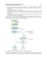
The overall bloc diagram of such integrated system for management of unsorted MSW is
shown in Figure 3. As told, all MSW is biostabilised before selection/screening to get a more
efficient separation and reduction of possible malodours.
MSW
PRE-TREATMENTS
BIO-STABILISATION
IRD < 800 mgO2/kgVS h
SEPARATION - I
< 80 mm
CURING/MATURATION
IRD < 400 mgO2/kg VS h
FSC
SEPARATION - II
< 25 mm
RBM
RBD
to RDF production
for energy recovery
to material recovery
to disposal
OPTION 2
OPTION 1
Process losses
% weight handled
=100
100
7575
25
40
35
30
5
5
Process losses
25
35
35
Fig. 3. Bloc diagram of integrated system for management of MSW
For the practical application of above schemes, the regional territory has been divided in 15
“Optimal Territorial Basins” (OTB): 4 in Province of Foggia (FG/1, FG/2, FG/4 and FG/5), 4
Integrated Waste Management – Volume I
62
in Province of Bari (BA/1, BA/2, BA/4 and BA/5), 2 in Province of Brindisi (BR/1 and
BR/2), 2 in Province of Taranto (TA/1 and TA/3) and 3 in Province of Lecce (LE/1, LE/2
and LE/3). Each OTB is served by treatment plants for:
a. “qualification” of recyclable fractions deriving from “source separation or separate
collection” of MSW;
b. “pre-treatment” of residual waste deriving from conventional “not-separate
collection”;
c. “biostabilisation” of above pretreated waste, followed by “mechanical separation” into
a “wet fraction” and a “dry fraction”, being the former (RBD) landfilled or submitted to
further curing for the production of RBM to be possibly reused for environmental
purposes, the latter (FSC) processed for conversion into RDF;
d. “landfilling” of process rejects or untreated waste during shutdown periods for
maintenance or emergency.
Operation of above point a) has the purpose to have a higher amount of selected fractions of
better quality just to give them a higher market value.
It has to be observed that, to optimise economic balances, the production of RDF and its
utilisation is planned not to be done in all OTBs, but in a few centralised Centres serving
more OTBs. This is the case of Province of Foggia, where 1 RDF production Centre is
planned to serve 4 OTBs, of Province of Brindisi to serve 2 OTBs, of Province of Lecce to
serve 3 OTBs, of Province of Taranto to serve 2 OTBs, and of OTB BA/1 serving also OTB
BA/4.
At the time of writing 10 treatment plants are in operation (OTBs of FG/3, FG/4 and FG/5;
BA/2 and BA/5; TA/1 and TA/3; LE/1, LE/2 and LE/3) and 1 is completed and ready to
start (OTB of BR/1).
4.3 Guidelines
To guarantee uniform technical designing of plants in the different OTBs, specific
Guidelines for each treatment section have been issued by the Commissariat Offices
(Commissariat for waste emergency, 1997, 1998a, 1998b, 1998c).
Guidelines require that, besides main working structures, all Centres shall be provided with
facilities destined to Support Services, subdivided into Management Services and Technical
Services.
The Management Services include:
- weighing;
- waste classification and recording;
- guardhouse;
- administration;
- social services for personnel,
while the following services and/or technological installations belong to the group of
Technical Services:
- motive/driving power and lighting electric installations;
- water supply system for drinking, hygienic and services uses;
- effluents treatment plant;
- surface water disposal system;
- fire protection system;
- earth plant and lightning strokes protection systems;
Planning the Management of Municipal Solid Waste:
The Case of Region “Puglia (Apulia)” in Italy
63
- storage, handling and materials loading/unloading areas, with sizes and characteristics
suitable for passage and operation of lorries, trucks and trailers;
- parking areas for vehicles and demountable containers, spare parts store.
4.3.1 Centres for qualification of recyclable fractions from separate collection
Such Centres shall be used for paper and cardboard, plastics, glass, aluminum cans, ferrous
and non ferrous metals (Commissariat for waste management, 1997).
The main equipment is the selection system, essentially consisting in a belt conveyor located
on a platform equipped with a sound-proof cabin and an air-change system. Operators,
standing at belt side(s), manually pick up the different fractions and store them in containers
placed below the belt. From the material remaining after the above selection, the ferrous
material is separated by a permanent magnet deferrization system, whilst aluminum and
non ferrous materials by an eddy current separator. The other materials deriving from the
selection which cannot be recycled are discharged in special containers, compatible with the
material itself, for disposal at authorized plants. Paper, cardboard and plastics must be
pressed and pressing devices must assure, for plastic wastes, their pressing in bales sizing
120x80x80 cm, each weighing 100-140 kg. A baling press for the compression of aluminum
cans must be also installed.
As far as the storage sites of glass, plastics, paper, cardboard and cans are concerned,
Guidelines require the realization of 3 sides walls cells in reinforced concrete with a height
of 2.5 m, width and length not lower than 3 m and 6 m, respectively, smooth concrete
pavement and protection against wear and tear, with a light slope (max 2%) towards the
open loading side, with a grating for collection and conveying of meteoric waters. The
storage sites for processed plastics and paper/cardboard must have a capacity sufficient for
the storage of, at least, a quantity corresponding to 2 units of useful load, equivalent to 200
bales, while the storage capacity of processed cans must be sufficient for the storage of at
least a quantity correspondent to 1 useful load, equivalent to 30 tons.
The Centres must be also equipped with a 80 t weighing balance with 18x3 m
2
platform, and
with additional equipment for materials handling, loading/unloading, storing, etc., in
number according to the potentiality of the Centre.
4.3.2 Centres for selection of unsorted wastes
Such Centres allow waste residuals from separate or undifferentiated collection or from
separate dry/wet collection to be delivered (Commissariat for waste management, 1998b).
Such plants must be located at least 1,500 m far from the limit of urban agglomerations and
of important or touristic areas and at 2,000 m far from hospitals, health or thermal centres.
Providing that all sectors must be equipped with suitable systems for odors and dust
control, in case using biofiltration apparatus, collection and storage of entering waste to be
sent to selection must occur in a confined space. The size of such sectors must allow the
storage of the maximum quantity of daily production for a period of 3 days, at least.
The separation system of the wet fraction from the dry one must allow (i) the bags breaking
and the waste size reduction preferably through shredding systems, excluding thin
comminuting techniques, incompatible with the organic materials nature, (ii) the separation,
through screening, of the wet fraction (undersize) from the dry one (oversize), (iii) the
separation of ferrous and non ferrous metallic materials.
Above system must be located in a shed with an industrial type pavement, water-proof and
suitable for the passage of mechanical means, as well as with a wastewater collection and
disposal system.
Integrated Waste Management – Volume I
64
Residuals from separation must be stored in special containers or tanks or piles properly
protected, compatible with the material characteristics for their subsequent treatment or
disposal at authorized plants. The size of the storing sector must allow a storing capacity of
the separates combustible material corresponding at least to 7 days, or in such a way as to
avoid any risk of hygienic and sanitary problems.
4.3.3 Centres for stabilisation / composting.
Such Centres allow solid waste residuals from separate collection and/or of separated
organics to be stabilised. As told, good quality compost can be obtained only if the organic
fractions are separately collected.
Such plants must be located at least at 2,000 m far from the limit of urban agglomerations
and of important or touristic centres and at 2,500 m far from hospitals, health or thermal
centres. All sectors must be equipped with suitable systems for odors and dust control,
eventually using biofiltration apparatus, while the collection and storage of entering waste
to be sent to selection must take place in a confined space. The size of such sectors must
allow the storage of the maximum quantity of daily production for a period of at least 3
days (Commissariat for waste management, 1998a).
Preliminary treatments shall allow the (i) size reduction of input waste, using systems
compatible with the organic materials nature, (ii) selection of ferrous and non ferrous
metallic materials, and (iii) e separation, through screening, of the other non processable
fractions (oversize).
The working cycle includes the two phases of primary biooxidation and curing, which must
take place in aerated windrows or closed reactors or mechanized vessels or confined piles.
Reactors and vessels must be tight, and the surfaces which the piles are placed on must be
water-proof and appropriately protected with industrial type floor suitable for the passage
of mechanic means. In anycase, wastewater drainage and collection systems, to be sent to
water conditioning or to reuse in the treatment cycle are required.
The total duration of the two above processing phases must fulfill normative requirements;
in particular, temperature must be kept for at least 3 consecutive days over 55 °C. A
sufficient oxygen quantity must be assured to keep the aerobic conditions of the mass
through the use of both fixed aeration systems and electromechanical equipments, and
handling means and/or mechanical turning machine to turn the material under treatment.
A final refining phase is also required to separate the foreign material eventually still
present in the mass of treated materials, to make uniform the product particle size and to
reach the desired final degree of humidity.
The final product must be stored in containers or tanks or piles adequately protected in
order to preserve its quality and agronomic characteristics and to avoid hygienic problems
due to recontamination. Packaging in bags with label in compliance with the law is
recommended.
4.3.4 Centres for production of refuse derived fuel
Centres for production of RDF are plants which get the selected fractions of fuel material
(e.g. FSC) for their transformation into a solid product to be reused for energy purposes in
existing industrial plants or in dedicated ones (Commissariat for waste management, 1998c).
In this case too, all sectors must be equipped with suitable systems for odors and dust
control, eventually through biofiltration apparatus. The collection and the storage of
Planning the Management of Municipal Solid Waste:
The Case of Region “Puglia (Apulia)” in Italy
65
materials to be sent to RDF production must take place in a confined space, dimensioned to
allow the storage of the maximum quantity of daily production for a period of at least 7 days.
The flooring of the shed must be of industrial type and equipped with a washing water and
wastewater collection and disposal systems, in conformity with the applicable regulations.
The production of RDF, to be realized in a suitable closed shed, must allow the (i) separation
of the dry fraction into light, thin and heavy fractions (ballistic systems or equivalent ones),
and (ii) production of a material in compliance with the quality standards established in the
agreements with the users (densifying systems or equivalent ones).
The final product must be stored in containers or vessels or piles adequately protected and
with a volume suitable to the Centre potentiality; in anycase it must assure a storage
capacity corresponding at least to 7 days of production.
4.3.5 Centres for energetical utilisation of refuse derived fuel
Centres for energetic utilization of (RDF) are plants which receive the selected fractions of
fuel material separated in the Centres for production of refuse derived fuel for its
combustion and energy production. Such plants must be located at least at 1,500 m far from
the limit of urban agglomerations and of important or touristic centres and 2,000 m far from
hospitals, health or thermal centres.
The characteristics of RDF to be sent to combustion must be in conformity with the current
technical standards, including the Standard UNI 9903-1.
All sectors must be planned in order to reduce dust, volatile organic compounds and odors
emissions, according to the best technologies available. The collection and the storage of
materials to be sent to combustion must take place in a confined space, dimensioned in
order to allow the storage of the maximum quantity of daily production for a period of at
least 7 days; the plant must be equipped with specific devices for the abatement of
particulate/dust, NO
x
, HCl, HF, SO
2
, organic micropollutants, and other inorganic
pollutants.
The other technical requirements are:
- stack height able to assure a good dispersion of pollutants and to protect human health
and environment;
- pavement and floorings of industrial type, equipped with washing water and
wastewaters collection systems;
- suitable energetic recovery section under thermal or electric form, with total efficiency
not lower than 20% with regard to electric energy production, to be calculated
according to the real value of RDF lower calorific value;
- measurement and recording of main working parameters of the energy production plant;
- ash and slag storage in containers or vessels or piles adequately protected and with a
volume able to assure a storage capacity corresponding at least to 7 days of production;
- quantification and characterization of mass flows coming out from the Centre;
- data visualization system to the public.
For handling the materials treated in the Centre, the same equipments of other above
mentioned Centres must be available.
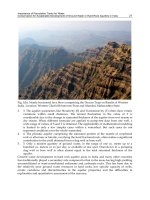
5. The Massafra plant
The first plant complying with requirements of the Puglia waste management regional plan
was that located in Massafra, serving the OTB TA/1 (Photo 1). The plant, whose technical
Integrated Waste Management – Volume I
66
specifications are summarised in Table 1, was built in 2003 and operated since 2004 by CISA
s.p.a., so has now cumulated almost 7 years of successful operations.
Photo 1. General view of the Massafra plant
Authorised capacity 110,000 t/y
Operating days 312 d/y
Daily capacity 350 t/d
Operating hours of mechanical systems 12 h/d
Throughput capacity 30 t/h
Table 1. Technical specifications of Massafra plant
Typical composition of RSU treated in the plant is shown in the following Table 2.
Main constituents of the plant are:
- waste receiving area with weigh-bridge;
- two-floors building for waste receiving and production of RDF, being the section for
waste receiving elevated of 2.5 m with respect to that for RDF production;
- two-floor building for offices and general services with controlling, monitoring and
supervision systems located on the second floor;
- building for biostabilisation of waste separated from that for production of RDF by a 10
m width road; this building includes a total of 13 biotunnels, being 4 of them possibly
utilized for RBM or compost production, and annexed auxiliary equipments, storage
containers/boxes for materials to be stabilized, and feeding system for wet-dry
separation and production of RDF;
- biofilter located close to the building for waste receiving and production of RDF, but at
the opposite side of the offices.
Planning the Management of Municipal Solid Waste:
The Case of Region “Puglia (Apulia)” in Italy
67
All the external access areas and the operating ways and roads are fully paved, and all the
plant area is confined by walling and wire fence.
All the produced RDF is recovered for energy generation at the Appia Energy power
station, that is located by the side of the waste treatment plant.
Item %
(according to UNI 9246)
Paper 24.20
Plastics 25.94
Cloth / Fabric 0.76
Wood 1.68
Glass 3.85
Metals 2.07
Inerts 2.66
Organics 10.00
Undersize <20 mm 27.53
Evaporation losses 1.31
Total 100.00
Table 2. Typical composition of MSW at Massafra plant
5.1 Biological treatment cycle
The overall biological treatment cycle is shown in Figure 4.
Receiving area
The MSW conferring occurs in a closed building which is maintained under light vacuum;
access doors are automatically operated for fast opening and closing. Wastes are
downloaded directly from trucks on the pavement of the building, and are handled by a
tyred loading shovel; during this operation, the operator of the tyred loading shovel checks
the waste to verify the absence of non-processable materials.
Pre-treatment
This operation includes primary shredding and separation of ferrous materials by a 50 t/h
slow-speed shredder with hydraulic control. The transferring belt is placed in storage pit,
thus making easier the loading operation of materials by the handling means. The
transferring speed is regulated by frequency variation.
The shredded waste is then transferred to storage boxes, where is taken by a tyred loading
shovel for its loading into the biostabilisation tunnels.
Biostabilisation
The biological stabilization process takes place in 13 tunnels (Photo 2). The process, which
includes stabilization and drying, requires 7 to 14 days, depending on the quality of waste.
Exhaust air is sent to a centralized biofilter to control odours.
Biotunnels are fully constructed in reinforced concrete, and equipped of an insufflating air
system from the pavement, through holes of squared mesh of 40 cm. Air fluxes and process
parameters are automatically controlled by a computerized system.
After passing through the material, air is recirculated. Material temperatures are
continuously monitored and air fluxes consequently regulated through variation of the cycle
of each fan which biotunnel is equipped with. The MSW biostabilisation cycle lasts 7-8 days,
Integrated Waste Management – Volume I
68
thus allowing a max Dynamic Respirometric Index of 800 mg-O
2
/kg-VS
*
h to be got, useful
for subsequent production of RDF.
The phases of the biostabilisation process are:
- hygienisation cycle with temperature continuously higher than 55 °C for at least 3 days;
the concrete biotunnels guarantee the uniformity of treatment for all the waste mass
thanks to the high insulating index of walls;
- after hygienisation, temperature is maintained at about 50 °C which is the optimal one
for the development of microflora and micetes working on organic substance
degradation; recirculation of treatment air guarantees uniform conditions of
temperature, moisture and aeration of the mass;
- treatment air flow rate is higher than 40 m
3
/h per ton of material; this allows
availability of enough air for cooling phases so the total time of treatment can be
conveniently reduced and time useful for biostabilisation consequently increased.
Fig. 4. Bloc diagram of the biological treatment cycle
Parameters controlled in each biotunnel are:
- inflated temperature, directly measured within the pile by thermometric probe inserted
through the biotunnel cover;
- temperature of air to be recirculated to the biotunnel and of exhaust air to be treated in
the biofilter;
- flow rates of fresh air and exhaust air;
- pressures inside the biotunnel, in air pipes, etc.
At the end of the biostabilisation treatment, the material is transferred to the wet-dry
separation section by a tyred loading shovel.
Planning the Management of Municipal Solid Waste:
The Case of Region “Puglia (Apulia)” in Italy
69
Photo 2. Biostabilisation tunnels
The analysis of control and monitoring system data evidenced that a fundamental requisite
for optimizing the biostabilisation process is the material size and homogeneity which
strictly depends on the previous shredding operation. Optimal size of the material to be
stabilized should range 120–150 mm, thus giving the material the necessary porosity and
also guarantee the flaking off of parceled and compressed materials. The type of shredder
installed in the plants is able to work in this direction.
In addition, the shredded material has to be submitted to biostabilisation in very short time,
just to fully utilize the organic load of waste for a fast and natural temperature increase
inside the waste pile during the initial biostabilisation phases. This fact occurs because the
fresh shredded material does contain soluble and easy degradable compounds which are
utilized by the mesophilic microorganism with production of heat necessary for the
subsequent thermophilic phase; a delayed load of biotunnels involves the dispersion of the
thermal energy accumulated during the mesophilic phase and, consequently, a not correct
development of the process. Such a procedure allows a hygienisation temperature of 55 °C
to be reached in 18 h.
For above reason, the choice of a porous pavement in the receiving area, instead of a storage
pit, showed to be successful because in a pit the material downloaded from the first trucks
remains at the bottom, so it is the last to be treated with possible developments of anaerobic
conditions which are dangerous for the process itself, and also causes malodors and leachate
release. Aeration through the pavement also avoids the negative effects of pressure on the
material, such those caused by systems adopting covered windrow systems.
The determination of Dynamic Respirometric Index on treated material is done on bi-
monthly base, while that of raw MSW entering the plant once a year, and any time the
collection system is modified or new wastes are conferred to the plant. Sampling procedures
are those standardized by the norm 9246 of the Italian standardization body, UNI.
Separation- I
As shown in the process diagram (Figure 3), after biostabilisation the material is screened in
a 80 mm openings equipment (Photo 3) where two fractions are separated.
Integrated Waste Management – Volume I
70
The undersized fraction, or wet fraction, which does mainly contain organic material, is for
80% directly landfilled as RBD, while a 20% portion is cured in an aerated static pile to
obtain RBM for subsequent use as cover material for landfill or other environmental
purposes.
The oversized fraction, or dry fraction (FSC), is destined to production of RDF.
Curing and Separation-II
The maturation section of the plant, consisting of 4 specific biotunnels, has not been used up
to now for the production of compost due to difficulties:
- in supplying the plant of selected organic material deriving from separated collection at
source;
- in finding a destination for the compost to be eventually produced, so this section is
only used for production of landfill cover material or land reclamation one.
However, above additional biotunnels can be used to expand the overall plant capacity and
flexibility.
Photo 3. Selection / Screening equipment
Planning the Management of Municipal Solid Waste:
The Case of Region “Puglia (Apulia)” in Italy
71
Production of CDR
As told, the oversized fraction from separation is processed to convert it into densified RDF.
After ferrous separation, an aeraulic device separates heavy components from light ones, the
latter consisting of pieces of plastics, paper, cardboard, polystyrene, insulating material, etc.,
which are treated by two secondary shredders which reduces the material size thus making
it acceptable to be treated by the subsequent horizontal draw bench densifiers, working in
parallel, to produce pellets.
A magnetic separator attracts further ferrous material, before the material is processed by
the densifiers, and again after them.
Figure 5 shows the bloc diagram of RDF production, and Photo 4 a particular of the
pellettizing equipment.
Fig. 5. Bloc diagram of RDF production
The densified material is automatically stored in containers for transporting to the Centre
for its energetic utilization, while the heavy components and other manufacturing rejects are
belt transferred to storage containers for subsequent disposal at authorized plants
In Table 3 the typical composition of RDF produced by the plant is summarized.
Process control
The control system manages not only all plant devices and equipment, but also records all
data of field instrumentations whose analysis made possible the optimization of the entire
treatment system.
The plant is also equipped with installations to control dust in the building of production of
RDF and air from all plant sections. As a matter of fact, all equipment in the building of RDF
production can produce some dust, so they are equipped with suction caps which are
connected to a bag filter. The filtered air is then returned to the biostabilisation building
which are maintained under light vacuum to avoid air emission outward.
Integrated Waste Management – Volume I
72
Item %
Cellulose 20.77
Wood 1.67
Polyethylene LWD 6.27
Polyethylene HD and Polypropylene 3.72
PET 1.91
Polystyrol 1.47
PVC 3.40
Cloth and Fabrics 2.89
Aluminum 0.58
Inerts 0.08
Undersize <20 mm 55.80
Losses 1.44
TOTAL 100.00
Table 3. Typical composition of produced RDF
Photo 4. Particular of the pellettizing equipment
All the closed ambients are maintained under vacuum to avoid diffusion of bad odors.
Picked up air is utilised in the biotunnels and then sent to the biofiltration system. In the
Planning the Management of Municipal Solid Waste:
The Case of Region “Puglia (Apulia)” in Italy
73
biofilter plenum, condensate collecting wells connected to the network ending in the
corresponding tank of humidification waters for their recirculation are placed.
Leachate from biotunnels, and water drained from all transit areas are collected and
transferred to treatment by static grate filter, storage and treatment at authorized plants.
5.2 Energy recovery plant
The energy recovery plant, whose general view is shown in Photo 5, occupies an area of
about 90,000 m
2
. It is operated by Appia Energy s.r.l.
It consists of the following sections:
- fuel transport and dosing;
- combustion and steam generation;
- combustion gas treatment;
- ash evacuation and storage;
- condensation;
- energy supply and automation.
By means of the pre-heating and superheating phases, produced steam gets pressure and
temperature conditions required by the turbine, where it is converted to mechanical energy
and then to electric energy through the alternator. All the produced energy is forced into the
national energy lines network due to agreement with the network operator.
The low pressure steam from the last turbine expansion stage is condensed to water in air
condenser and enters again the thermodynamic cycle.
Photo 5. General view of the power station for energy recovery
Combustion gases, after exchanging their heat with water steam, are submitted to treatment
for abatement of polluting compounds.
Steam generator is supported by a steel construction which is covered to protect the
generator from atmospheric agents. Maximum height of the structure is 40 m. The stack is 45
m tall and has a diameter of 1.6 m.
Integrated Waste Management – Volume I
74
The turbo-group is installed in a fire-resistant and sound adsorbing cabin. The
interconnecting system to the national electrical network is located near the turbo-group and
close to the existing electric lines; it includes a transformer (6.3 - 150 kV).
The following Table 4 summarizes the main operating data of the energy recovery plant.
Produced
Energy
Power consumption
(auto consumptions)
Energy
forced to national
network
Gasoil
for combustion
kWh kWh kWh Litres
69,672,000 12,524,000 59,040,000 463,286
Table 4. Main operating data of the energy recovery plant
Other power plant data are:
- gross electric power ~12.5 MW
e
,;
- net electric power ~10.0 MW
e
;
- thermal power ~49.5 MW
t
;
- net efficiency ~21%.
Industrial water needs have been estimated in about 18 m
3
/h during the start-up phase and
in about 7.2 m
3
/h during the operation one, but experience showed that real needs during
the operation phase could be as low as 2-3 m
3
/h.
The plant can be fed with RDF (main fuel) produced by the MSW treatment plant, and with
gasoil (auxiliary fuel) during start-up and emergency periods. RDF consumption is
estimated in about 100,000 t/y.
Interferences of the energy recovery plant with environment include gaseous, liquid, solid,
noise, and electromagnetic emissions.
Gaseous emissions into the atmosphere are summarized in Table 5. Legal limits are reduced
by 20% with respect to the national ones because the plant area is classified at
environmental risk due to the presence of many industrial installations.
Item Units Value
Wet gases flow rate Nm
3
/h 80,000 – 100,000
Dry gases flow rate Nm
3
/h 60,300 – 89,000
Oxygen (as O
2
) % ~ 11
Exit temperature °C ~ 170
Table 5. Characteristic emission values of power plant
Reduction of sulphur oxides is obtained within the combustion camera by injection of lime
above the fluidised bed. Reduction of nitrogen oxides is obtained through injection of
ammonia solution in the post-combustion zone of the furnace. Finally, reduction of acid
gases and organic micropollutants is obtained through chemical reactions after dry injection
of alkaline substances, such as sodium bicarbonate and activated carbon, in a reaction tower
downstream the steam generator. The treatment is completed by a bag filter which retains
particulate/dust produced during the combustion process, and residues of the reaction for
the abatement of acid gases.
Planning the Management of Municipal Solid Waste:
The Case of Region “Puglia (Apulia)” in Italy
75
The plant is also equipped with a double system of continuous monitoring of emitted
pollutants (CO, NO
2
, O
2
, Particulate, SO
2
, HCI, HF). Other pollutants, such as IPA, Heavy
metals, Dioxins, Furans, are also periodically checked.
The authorized limits for stack emissions are reported in the following Table 6.
The system dealing with emissions of liquids is based on appropriate systems which allow
most of the liquid wastes to be reutilized in the plant.
Two independent networks respectively collect raining waters and/or those coming from
roads, service ways and areas, buildings roofs and coverings, and process waters and
sanitary effluents.
Waters from the first network are treated by sedimentation, separation of solids substances
and oils removal. At the end of the treatment their characteristics allow their reutilization
and/or disposal with respect of the applicable normative.
Waters from the second network are treated by sedimentation, oils removal, biological
treatment, pH correction and chlorination. At the end of the treatment, a portion is sent to
external treatment plants for treatment and disposal, while another portion is utilized to
moisten fly ashes for the abatement of their dustiness.
Main solid waste produced by the energy recovery plant include sand, bottom ashes and fly
ashes which are disposed of according to the applicable normative. Bottom ashes amount to
5,000-6,500 t/y, and fly ashes to 14,000-17,500 t/y.
Compund Max allowed concentration
(mg/m
3
)
Particulate / dust 8
Total Carbon (TOC) 8
Hydrochloric acid (HCl) 8
Hydrofluoric acid (HF) 0.8
Sulphur oxides (SO
2
) 40
Nitrogen oxides (NO
x
) 160
Table 6. Authorized limits for gaseous emissions
Periodical monitoring campaigns to check the acoustic emissions of the plant are also
planned and carried out by the official Institutions charged of this duty.
Analogously, during plant operation measurements of the electro magnetic field are done to
verify the respect of the normative limits of non ionizing radiation emissions.
Since 2006, the plant got and operates a certified ISO 14001:2004 EMAS system of
environmental management.
6. Conclusion
The correct management of municipal solid waste, in a context of a sustainability concept,
requires adoption of appropriate integrated systems to:
- maximize the use and utilisation of waste material and energy content;
- minimize the impact of waste on the environment.
In the Region Puglia (Apulia), SE of Italy, the “Commissariat for Environmental
Emergency” was established since 1997 having, among others, the duty to develop the
Integrated Waste Management – Volume I
76
regional plan for municipal solid waste management in conformity with European and
National regulations.
With the Commissary Decree 296/2002, as completed and adjourned by the Decree
187/2005, the Commissary approved the “Regional Solid Waste Management Plan”, after
introducing on 1997 and 1998 technical specifications for the mechanical-biological
treatment of solid waste remaining after separation at source of selected fractions.
Basically, above mentioned Commissary Decrees, require the:
- development of “source separation” schemes with the target for 2010 of 55% of MSW
separately collected to be subsequently handled for material recoveries;
- operation of Centres for the “qualification” of specific recyclable fractions deriving from
above “source separation or separate collection”;
- “biostabilisation” of urban waste remaining from separate collection prior to the
separation of a treated wet fraction to be landfilled, or used for environmental
purposes, and a dry fraction to be used for the production of refuse derived fuel.
The management plan split up the regional territory into 15 “Optimal Territorial Basins”
each mainly served by treatment plant for:
- “qualification” of specific recyclable fractions deriving from “source separation or
separate collection” of urban waste;
- “pre-treatment” of residual urban waste deriving from conventional “not-separate
collection”;
- “biostabilisation” of above pretreated waste;
- “mechanical separation” of biostabilised material into a “wet fraction” and a “dry
fraction”, being the former landfilled or submitted to further curing for the production
of materials to be possibly reused for environmental purposes, the latter (FSC)
processed for conversion into RDF;
- “landfilling” of process rejects or of untreated waste during shutdown periods for
maintenance and/or emergency.
The first plant complying with requirements of the waste management regional plan was
that located in Massafra, with an authorised capacity of 110,000 t/y.
Core of the plant is the biological stabilization process that takes place for 7-14 days in 13
biotunnels. The biostabilised material is then screened to obtain a “wet” (undersized)
fraction and a “dry” (oversized) one. Then the dry fraction is processed to be converted into
densified refuse derived fuel.
Finally, produced RDF is burnt in a dedicated power plant to recover energy. Main
characteristics of the power plant are a gross electric power of about 12.5 MW
e
, a net electric
power of about 10.0 MW
e
, a thermal power of about 49.5 MW
t
, and a net efficiency of about
21%.
The plant has now cumulated almost 7 years of successful operations fully complying with
limits imposed by applicable regulations.
7. Abbreviations
DRI Dynamic Respirometric Index
EU European Union
FSC Treated (biostabilised) dry fraction for production of refuse derived fuel (RDF)
MSW Municipal solid waste
OTB Optimal territorial basin
Planning the Management of Municipal Solid Waste:
The Case of Region “Puglia (Apulia)” in Italy
77
RBD Treated (biostabilised) wet fraction for disposal in landfill
RBM Further treated (cured/matured) wet fraction for environmental utilisation
RDF Refuse derived fuel
8. Acknowledgements
Thanks are due to Commissariat for Environmental Emergencies in Region Puglia (Apulia),
C.I.S.A. s.p.a. and Appia Energy s.r.l. for kindly providing the authors of information,
documents and characteristics of the plant for municipal solid waste management located in
Massafra (Italy).
To this purpose, opinions and statements expressed in the Chapter are those of the authors
and not necessarily those of above mentioned Institutions and Companies.
9. References
Adams, W.M. (2006). The Future of Sustainability: Re-thinking Environment and
Development in the Twenty-first Century, Report of the IUCN Renowned Thinkers
Meeting, pp. 1-18, Zurich, Hotel Uto Kulm, January 29-31
Commissariat for waste management (1997). Technical specifications for the realisation of
Centres for qualification of recyclable fractions from separate collection.
Commissary Decree, 95, published in Region Puglia Official Bulletin (B.U.R.P.) nr.
13, Bari, February 5 (in Italian)
Commissariat for waste management (1998a). Technical specifications for the realisation
of Centres for stabilisation/composting, Commissary Decree, 113, published in the
Region Puglia Official Bulletin (B.U.R.P.) nr. 113, Bari, January 19 (in Italian)
Commissariat for waste management (1998b). Technical specifications for the realisation
of Centres for selection of unsorted wastes Commissary Decree, 154, published in
the Region Puglia Official Bulletin (B.U.R.P.) nr. 41, Bari, April 30
Commissariat for waste management (1998c). Technical specifications for the realisation
of Centres for production of refuse derived fuel, Commissary Decree, 228,
published in the Region Puglia Official Bulletin (B.U.R.P.) nr. 116, Bari,
November 19
Marmo, L. (2002). Management of biodegradable waste - Current practice and future
perspectives in Europe, Waste Management World, Review Issue 2002-3, 75-79,
July-August
Spinosa, L. (2005). EU developments in sludge regulation and characterization,
Proceedings of 1
st
National Symposium on Sludge Management, 11-26, Dokuz Eylul
Univ., Izmir, March 23-25.
Spinosa, L. (2007a). Sewage sludge co-management: developments in EU legislation and
characterization procedures, Int. Conf. on Sustainable management of recycled water:
from recycling to sewage sludge use, ISR (Instituto para la Sostenibilidad de los
Recursos”), www.isrcer.org, Barcellona, March 14
Spinosa, L. (2007b). Sewage sludge co-management for energy recovery: developments in
EU legislation and characterization procedures, II Int. Conf. on Energy recovery
Integrated Waste Management – Volume I
78
from waste and biomass, ISR (Instituto para la Sostenibilidad de los Recursos”),
www.isrcer.org, Madrid, October 24-26
Spinosa, L. (2008). Co-management of sludge with solid waste: towards more efficient
processing, Water 21, December issue, p. 21
Williams, P.T. (2005). Waste Treatment and Disposal (2
nd
ed.), John Wiley & Sons Ltd, ISBN
0-470-84912-6, Chichester
5
Strength and Weakness of Municipal and
Packaging Waste System in Poland
Joanna Kulczycka
1
, Agnieszka Generowicz
2
and Zygmunt Kowalski
3
1
Mineral and Energy Economy Research Institute, Polish Academy of Sciences
2
Institute of Water Supply and Environmental Protection – Cracow
University of Technology Poland
3
Institute of Chemistry and Inorganic Technology
Poland
1. Introduction
The European Union's approach to waste management is based on three principles:
prevention, recycling, and reuse. The introduction to Directive 2006/12/EC of the European
Parliament and the Council on Waste states that “the recovery of waste and the use of
recovered materials as raw materials should be encouraged in order to conserve natural
resources”. According to the newest Directive 2008/98/EC on waste recovery is one of the
five objectives of environment-friendly waste management. The targets for re-use and
recycling of waste, which should be attained by 2020, is:
for re-use and the recycling of waste materials such as at least paper, metal, plastic and
glass from households and possibly from other origins as far as these waste streams are
similar to waste from households, shall be increased to a minimum of overall 50% by
weight;
and for non hazardous construction and demolition waste: defined in category 17 05 04
in the list of waste shall be increased to a minimum of 70% by weight (EC, 2008).
Moreover, the Directive 2004/12/EC (amending Directive 94/62/EC) on packaging and
packaging waste was adopted. This Directive aims to harmonize national measures in order
to prevent or reduce the impact of packaging and packaging waste on the environment.
Therefore the recovery (60% in 2014) and recycling (55% in 2014) targets were established
and must be met by each member state. In Poland, although the recycling level for
municipal waste has been increasing, it still remains at a very low level (approximately 8%).
One of the reasons for this is that there are two parallel systems, which are responsible for
separate collection, i.e.:
system for local communes, which are responsible for management of all type of
municipal waste,
system for entrepreneur-manufactures, which are obliged for recovery and recycling of
packaging waste.
On both systems the market conditions, i.e. relatively high cost of separate collection, which
depends on the amount of collected material, the unit size of the waste material, the quality
Integrated Waste Management – Volume I
80
of the waste materials, changing price of waste materials, lack of education have significant
influence and not allow implementing new technological solutions. As both the waste
material obtained from separate collection from municipal waste and the waste packaging
material should be deliver to recycling companies, the cost of their collection is a decisive
factor in respect of the profitability of this process. As the cost of collection of individual
waste is usually higher then bulk packaging and transport packaging waste, system for
entrepreneur-manufactures is usually focus on the latter collected. The demand from Polish
producers for waste materials (glass, paper, plastic) is relatively high, even the proper
quality of waste with low price is required; therefore the system for entrepreneur-
manufactures has higher potential to develop.
The aim of this chapter is to analyze the strength and weakness of existing systems of waste
management in Poland, the assessment if the EU requirements with current systems could
be achieved till 2020 and the proposal how to develop – based on best EU practice – these
systems to promote both the recovery and recycling of separate collection of household
waste and packaging waste.
2. The strength and weakness of local communes system
In the EU old members the planning of waste management had been developed since 1970s.
In that time in most of EU new members there was central planned economy, with quite
well developed system for glass reuse and metal collection. During the transformation
period the waste management was not the most important subject and the waste landfilling
was the most popular option. After joint the EU it was necessary to implement the EU
requirements. With the EU financial support (structural funds) first it was necessary to close
the ineffective landfills and then to build the system for recovery and reuse. Unfortunately
this is a very slow process. Numerous economic and legal changes concerning waste
management have been introduced in Poland over the last 10 years. As a result, the amount
of waste deposited in landfills sites has been diminishing, dropping from over 95% a few
years ago to approximately 85% last year. According to the Central Statistical Office (GUS),
over 12 million Mg of waste, i.e. 319 kg per person, was generated in Poland in 2009, while
about 10 million Mg (264 kg/per person) was collected, of which 8.469 million Mg was
deposited in landfill sites, 0.101 million Mg was incinerated, 0.508 million Mg was subjected
to biological and mechanical treatment methods, and 0.796 million Mg was segregated from
mixed waste. From collected household waste 0.543 million Mg was collected separately for
recycling, predominated by glass, paper and cardboard (Fig. 1 and 2).
Segregated collection has been increasing, though very slowly, mainly for economic reasons
such as the fact that the price of the material separated from the waste remains low, and
therefore there is not interest of implementing new technological solutions. As one of the
aims set out in, for example, the National Waste Management Plan 2010 and the ecological
policy, is to increase the recovery or recycling of waste material from household waste
(glass, paper, metal) from the current level of 8%, to 50% of the overall quantity by 2020,
new solutions should therefore be developed for the promotion of both separate collection
and the segregation of material from mixed waste.
In some communes, the selective collection of waste is financed from budget sources, as the
communes are responsible for keeping their region clean. A company, chosen by means of
open bidding, empties the special selective waste collection containers, known as 'bells'. In
2004, the average total cost, including investment, for segregated collection in communes
Strength and Weakness of Municipal and Packaging Waste System in Poland
81
Fig. 1. Municipal solid waste managed in 2004-2009
Fig. 2. Segregated municipal waste collection in 2009 [thousand Mg per year]
Integrated Waste Management – Volume I
82
varied from PLN 235/Mg (glass) to over PLN 1.160/Mg (aluminium) (Poskrobko, 2005).
Similar cost levels for waste collection were obtained in various towns in 2006, e.g. in
Tarnów, the average cost was over PLN 600/Mg (Report, 2007). Most communes concluded
that separate collection is not in the least profitable, with every PLN 1 received for the
material obtained having incurred a collection cost of PLN 4. In order to reduce collection
costs, the collection companies have now introduced a bag system. The cost of collecting
paper in 120 litre bags was PLN 60/Mg, with plastic costing PLN 200/Mg and glass, in 80
litre bags, costing PLN 27/Mg (OGIR, 2008). An even more effective system proved to be the
provision of one bag for mixed paper, plastic and glass waste. This solution made it possible
to increase the amount of waste for recycling, and to cover the costs of collection for some
types of waste material; for example, the price of waste paper might then be approximately
PLN 100/Mg. However, even if some income could be earned from the sale of paper, plastic
materials, glass and aluminium tins for recycling, it would not reach a level permitting
investment in, and the development of, such an operation.
However, this system is fully dependent on market conditions, which are changeable.
Therefore, other incentives for promoting recovery should thus be implemented, for
instance, a system of awards for individual 'collectors', educational measures, or the seeking
of financial support from Structural Funds for new technological solutions, and so forth.
The strength and weakness of local communes system is presented in table 1.
Even there are some improvements in waste management in Polish regions, it is important
to elaborate in regional plans a conceptual model, which can promote waste recycling and
recovery including regional conditions. Such model was proposed e.g. in South East
England. The model was developed for the recycling chain for each priority materials. The
five stages model has been analyzed and it included: collection, pre-processing
(sorting/segregation), densification (volume/size reduction), reprocessing (conversion ratio
into raw material) and fabrication (produce/product). This structure has been proposed to
each priority material to establish the size and distribution of capacity at each point in the
chain. It is recognized that some routes combine steps in the chain. For example newspaper
recycling to newsprint may go direct from collection to reprocessing and fabrication (Potter,
2006). Based on such model the regional plans should set realistic targets for all form of
waste. It is particularly important that communes should work together in the area where
there are opportunities to achieve better value for money and to achieve sustainable waste
management.
Moreover, for the evaluation of environmental impact of waste processes or systems one of
the most respected, popular and widely used in the EU method is LCA (Life Cycle
Assessment). The method has been seized, inter alia, to develop The Strategic
Environmental Impact Assessment for the National Waste Management Plan in the
Netherlands and Strategic Environmental Impact Assessment for the Waste Management
Plan of the region of Liguria in Italy. Worldwide, there are many programs that use the LCA
for supporting modelling of waste systems as well as evaluating their impact on the
environment, i.e. IWM-2 (Integrated Waste Management II), WRATE (The Waste Resources
Assessment Tool for Environment), TRACI (Tool for the Reduction and Assessment of Chemical and
Other Environmental Impacts), EASEWASTE (Environmental Assessment of Solid Waste Systems
and Technologies), ORWARE (Organic Waste Research), WISARD (Waste – Integrated Systems for
Assessment of Recovery and Disposal), and more general software as SimaPro and GaBi. These
programs are used to evaluate both the existing as well as the modelling of new waste
management systems and to determine the environmental benefits of their modernization.
Strength and Weakness of Municipal and Packaging Waste System in Poland
83
Introduction of such assessment could be beneficial also for new members, especially, as
some proposals have already been done by JRC, Ispra (Koneczny et al., 2007).
strength weakness
the planning system – based on the EU
experience – has been introduced including
aims, tasks and costs of its realization
lack of proper legal regulation which allow
communes to manage the waste as the
owner of waste. The owner of waste could
be transport companies or owners of waste
management facilities, i.e. sorting
installation or landfills
communes started to cooperate with each
other creating larger organization system
for separate collection
communes are relatively small, therefore the
management of waste is dispersed, and as a
result there are not enough specialists
responsible for waste management,
planning and reporting in communes
the existence of environmental fee and fines
system, which are separate from tax system
lack of common scheme for collecting and
recording data for type of waste, methods of
recovery and recycling, etc.
small progress in separate collection has
been achieved in last years
there is not regional system of waste
management, which should be connected
with the regional conditions i.e. if there is a
glass factory in the region the system of
glass collection should be promoted
the separate collection system (i.e. bells or
bags) is available for about 50% inhabitants
in some regions in Poland, but not all
inhabitants are used it
relatively low cost of landfilling (including
environmental fee) compared to other
methods
availability of financial support for new
installations and education from EU –fund
as well National Fund of Environmental
Protection and Water Management
lack of systematic education as well lack of
education provided by individual regions
lack of economic encouragement for privet
investors for development of separate
collection, therefore there are only few
sorting plants where waste from individual
household should be cleaned
there are not legal instruments to force to
achieve the indicated in local and regional
plans level for separate collection
Table 1. The strength and weakness of local communes system in Poland
3. The strength, weakness of entrepreneur – manufactures system
(packaging waste)
Poland has already adopted the majority of the EU regulations, e.g. the Directive
2004/12/EC (amending Directive 94/62/EC) on packaging and packaging waste, which
Integrated Waste Management – Volume I
84
imposes the obligation of adopting specified packaging waste recovery and recycling levels
on Member States. The Directive was introduced into Polish law in 2001, and updated over
the course of the following years. The entrepreneur-manufactures or importers of packed
materials were obliged to attain the appropriate percentage level for mass of the packaging
waste towards the implemented packaging mass. The legislation permits the delegation of
this obligation to a recovery organization. If they fail to attain the statutory level of
recycling, they are obliged to pay a product fee for the difference between the required and
the achieved level of recovery and/or recycling, expressed in product weight or quantity
1
.
The fees are imposed on entrepreneur-manufactures or importers of packaging materials.
The system is very complicated, as the duty imposed on an individual company for different
types of packaging material, and not on the total tonnage of packaging material, can be met
by company itself, or by a recovery organization. The product fee is in correlation with the
collection costs, but the cost of collection from an industrial source (bulky packaging waste)
is several time lower than from individual one. In 2008, the product fee varied from PLN
0.26/kg for glass to PLN 2.37/kg for plastic. In general, being higher than the price, which
can be obtained for material separated from municipal waste (Kulczycka & Kowalski, 2010).
The system seems to be very effective, given that official statistics suggest that the required
level of recycling for all types of packaging material was not only achieved, but, in a number
of years, was even significantly exceeded (tab. 2). The very high level of recycling in 2004-
2006 presented here was mainly due to the system of classification introduced by the
Ministry of the Environment, whereby if required annual recovery and recycling levels
excess 100%, were carried forward to the report for the next year. This was amended in 2007
and from then on reported recovery and recycling levels have not included the
aforementioned surplus (GUS, 2009).
Year
2003 2004 2005 2006 2007 2008 2009 2014
A R A R A R A R A R A R A R R
Plastics 16.8 10.0 22.4 14.0 30.3 18.0 36.9 22.0 28.0 25.0 23.9 16.0 21.5 17.0 22.5
Aluminum 27.1 20.0 33.3 25.0 86.7 30.0 110.4 35.0 82.0 40.0 60.9 41.0 64.2 43.0 50.0
Steel 14.4 8.0 17.3 11.0 23.4 14.0 34.1 18.0 21.2 20.0 26.5 25.0 33.6 29.0 50.0
Paper 52.9 38.0 57.0 39.0 65.4 42.0 85.6 45.0 69.1 48.0 67.2 49.0 50.9 50.0 60.0
Glass 20.4 16.0 31.2 22.0 38.4 29.0 48.0 35.0 39.7 40.0 43.9 39.0 41.9 430 60.0
Natural
materials
9.0 7.0 19.4 9.0 47.2 11.0 73.4 13.0 47.8 15.0 26.3 15.0 23.1 15.0 15.0
Multi material 13.5 – 14.2 – 22.5 – – – – – – - - - -
A – achieved; R – required
Table 2. Required and attained recycling and recovery levels for packaging material in 2003-
2009 and required level for 2014 (in percent %)
Source: GUS
1
The Minister of the Environment's Regulation of 14 June 2007 on annual levels of recovery and
recycling of packaging and post-usage waste (O. J. No. 109 item 752) stipulated the required level of
recovery and recycling.
Strength and Weakness of Municipal and Packaging Waste System in Poland
85
In Poland the quantity of packaging product launched on to the market has increased from
approximately 3.1 million Mg in 2005 to about 3.8 million Mg in 2009, and officially about
37% of packaging waste undergoes recycling process. At over 43% the main packaging
material is paper, namely packaging made from corrugated and solid cardboard and glass
(fig. 3). Bulk packaging and transport packaging waste are predominant here, as they are
easy to localize because they occur in the trade and industry sectors. Glass packaging holds
second place owing to the extensive production of the disposable packaging that facilitates
the disposal of packaging waste.
Fig. 3. Recycled packaging waste Poland in 2009 [thousand Mg]
Source: GUS
In spite of possessing the higher capacity for recycling especially for plastics and glass the
owners of the recycling companies are unable to bear the high costs of selective collection.
Meanwhile, the entrepreneur-manufacturers limit themselves to the statutory recovery and
recycling levels to which they are bound. Product fee sanctions can be imposed on the
entrepreneur-manufacturers only in cases where these levels are not met; at the same time,
most of them are able to achieve this level owing to the fact that they can fulfil their
obligations by means of Recovery Organization on the free market to buy so-called 'receipts'
(there are about 40 of such Recovery Organizations on Polish market). An organization
introducing packaging and products on to the market can buy the appropriate amount of
'virtual receipts’; corresponding to the quantity it should meet in order to fulfil its recovery
and recycling obligations. The financial resources for fulfilling this obligation are known as
a 'recycling payment'. When the act initially came in to force, these recycling payments were
high, though they did not exceed 50% of the product payment. However, as the system was
not watertight, some 'virtual receipts' were incorporated in the relevant calculations several
times, and the price of the recovery payment thus dropped significantly. As a result about
producers and importers of packaging waste paid 5 million PLN/year as a product fee,
whereas about 60 million PLN/year to Recovery Organizations in last years, whereas the
real cost of collection of 1,5 million Mg of packaging waste was estimated on 300 million
PLN (Kawczyński, 2009).
The existing entrepreneur-manufactures system is presented on Fig. 4.
The revenues from product fees are distributed (according to the Act on requirements for
entrepreneurs with respect to management of some wastes and product and deposit fees-
consolidated text O. J. 2007, no. 90 item 607) to: