Advances in Satellite Communications Part 13 doc
Bạn đang xem bản rút gọn của tài liệu. Xem và tải ngay bản đầy đủ của tài liệu tại đây (2.2 MB, 15 trang )
New Antenna Array Architectures for Satellite Communications
169
MSS services are divided into two groups, those that offer a regional coverage usually with
GEO satellites, and those which offer a global coverage based on LEO or MEO satellite
constellations. Depending on the coverage, there are some examples for MSS with regional
coverage as the mobile satellite system (MSAT) in EEUU, Canada and South America, Optus
in Australia, N-Star in Japan, Asia cellular satellite (ACeS) in Asia or Thuraya in the Middle
East and in the North of Africa. While for MSS of global coverage there are some examples
as Iridium, ICO Global Communications, Globalstar, Teledesic, etc. (Evans, 2009; Wu, 1994).
Most of the MSSs work at L and S band, new applications on satellite to mobile terminal
links work at X, Ku and Ka band, and satellite to base station connections work at L, S and C
band. A number of applications is broad and lead terrestrial telecommunications market to
offer a wider coverage: high speed voice and data (internet access, SMS, VoIP), digital video
broadcasting by satellite 2 (DVB-S2) and digital video broadcasting satellite services to
handhelds (DVB-SH), global position system (GPS) and Galileo, security, control and
machinery monitoring on ships and aircrafts, teleeducation or telemedicine.
These modern satellite communications systems require new antenna solutions for base
stations, aeronautical applications or personal communications services (PCS) on-the-
move (Fujimoto & James, 2001). Within these applications, antenna array systems are
potentially the best choice due to, as discussed above, its capability to perform
electronically steering or beamforming, increase the antenna gain, and conform over
curved or multifaceted surfaces the radiating elements. Portable antennas for PCS must be
easy to install and mechanically robust, besides compact and lightweight (García et al.,
2010) as the antenna array presented in Fig. 4.a. The design of antenna systems to provide
high data rates for reliable PCS boarded on ships is not so strict in term of the geometrical
requirements because it does not have space limitations (Geissler et al., 2010). However, in
the case of land or airborne vehicles, geometrical and mechanical constraints are more
severe. Antennas for terrestrial vehicles must be low profile, and for airborne vehicles
aerodynamic shapes must be considered (Baggen et al., 2007; Vaccaro et al., 2010).
Moreover, for the civil market conformal antenna arrays (Schippers, 2008; Kanno et al.,
1996), or multi-surface arrays (Khalifa & Vaughan, 2007) are suitable choices to deal with
the system aesthetic partiality.
Technological challenges have been faced during the implementation of satellite
communication systems in the last decades. The design of a Test-Bed flexible and modular
for testing or debugging beamforming algorithms and receiver architectures is an invaluable
contribution in the educational, research and development area on satellite communication
systems. The adaptive antenna array Test-Bed (A3TB) concept is based on the use of antenna
arrays with beamforming capability to receive signals from LEO satellites (Salas et al., 2008).
The scope of the A3TB is to probe the concept of antenna arrays applied to ground stations
instead of reflectors for different applications, such as telemetry data downloading. It is also
a good chance for Universities and Research Centers aiming to have their own ground
station sited in their installations.
The A3TB ground station relies on the use of an antenna array to smartly combine the
received signals from the satellite thanks to the implementation based on software defined
radio (SDR) technology. The advantages of the SDR implementation is that A3TB
architecture can be used to process any received signal from LEO satellites in the band
imposed by the radio frequency (RF) circuits. Moreover, most of the processing is performed
in software, so that appropriate routines can be used to process any received signal. The
A3TB can be used to analyze the feasibility of different receivers and beamformer
Advances in Satellite Communications
170
algorithms, regarding the capability to switch the receiver architecture in terms of the
synchronizer algorithm configuration (Salas et al., 2007).
The current version has been developed to track The National Oceanic and Atmospheric
Administration (NOAA) satellites in the very high frequency (VHF) band, in particular, the
automated picture transmission (APT) channel (Salas et al., 2008). Previous versions of A3TB
dealt with low rate picture transmission (LRPT) signals from the meteorological operational
satellite-A (MetOp-A), where a complete receiver with beamforming and synchronization
stages has been implemented (Salas et al., 2007; Martínez et al., 2007).
3. Antenna arrays for satellite communications
Satellite applications require compactness, lightweight and low cost antenna systems to be
mounted on a terrestrial vehicle, an aircraft or a ship, or as a portable man-pack or a
handset, and to be competitive against ground systems. Its major advantage is the
possibility of getting a wider or even a global coverage. For such purposes, antenna arrays
offer the technology to get a directive system whose steering direction can be electronically
and/or mechanically controlled. However, planar arrays usually cannot steer more than 60º-
70º from the normal direction of the antenna (Mailloux, 2005). Thus, when a wider angular
coverage is required conformal arrays are an appropriate option (Josefsson & Persson, 2006).
Arrays can approximate conformal shapes, such as spheres or cylinders, using several
planar arrays, simplifying fabrication of active components (Sierra et al., 2007).
Since the low cost and low weight specifications are of importance, micro-strip antennas are
mostly used, due to its capacity to be printed over a dielectric substrate with
photolithography techniques. Low cost and low permittivity substrates are usually used
such as FR4 or PTFE with different quantities of glass or ceramic impurities. For more
demanding applications, ceramics, like alumina or high/low temperature co-fired ceramics
(HTCC/LTTC) allow the use of smaller components thanks to its high permittivity, and give
robustness against mechanical stresses and high temperatures.
3.1 Geodesic antenna array for satellite tracking in ground station
The aim of using a single antenna for tracking many satellites at the same time avoiding
mechanical movements as well as its inexpensive cost make these antennas an alternative to
be considered (Salas et al., 2008). Multi-beam ability and interference rejection are facilitated
thanks to the electronic control system of such antennas that improves the versatility of the
ground stations.
The GEODA is a conformal adaptive antenna array designed for MetOp satellite
communications with specifications shown in Table 1. This antenna was conceived to
receive signals in single circular polarization (Montesinos et al., 2009). Subsequently, in
recent efforts the system has been upgraded also for transmission and double circular
polarization (Arias et al., 2010). Hence, operating at 1.7 GHz with double circular
polarization it can communicate with several LEO satellites at once in Downlink and
Uplink. Current structure is the result of a comprehensive study that valued the ability to
cover a given spatial range considering conformal shape surface and a given beamwidth
(Montesinos et al., 2009). As Fig. 1 shows, GEODA structure consists of a hemispherical
dome placed on a cylinder of 1.5 meters height. Both cylinder and dome are conformed by
30 similar triangular planar arrays (panels). Each panel consists of 15 sub-arrays of 3
elements (cells). The radiating element consists of 2 stacked circular patches with their own
New Antenna Array Architectures for Satellite Communications
171
RF circuits. The principal patch is fed in quadrature in 2 points separated 90º in order to
obtain circular polarization. The upper coupled patch is used in the aim of improving the
bandwidth.
Each panel is able to work itself as an antenna since they have a complete receiver that
drives the 1.7 GHz signal to an analog to digital converter (ADC). In order to adapt the
signal power to the ADC, it is mandatory to implement a complete intermediate
frequency (IF) receiver consisting of heterodyne receiver with an automatic gain control
block. Hence, each triangular array has active pointing direction control and leads the
signal to a digital receiver through an RF conversion and filtering process. To follow the
signal from the satellite, the main beam direction has to be able to sweep an angle of 60º.
In this way, it is needed a phase shift in the feeding currents of the single radiating
element. Previous calculations have demonstrated that 6 steps of 60 degrees are needed to
achieve the required sweeping angle. An adaptive digital system allows the adequate
signal combination from several triangular antennas. The control system is explained in
(Salas et al., 2010).
Parameter Specification Parameter Specification
Frequency range [GHz]
Tx:
Rx:
1.65 to 1.75
1.65 to 1.75
Isolation between Tx
and Rx [dB]
>20
Polarization
Dual circular for
Tx and Rx
bands
VSWR
1.2:1
G/T [dB/K]
For elevation >30º
For elevation 5º
3
6
SLL [dB]
-11
EIRP [dBW]
36
Size [m]
1.5x1.5x3
3dB beamwidth [deg.]
5
Accuracy steering [deg.]
±1.4
Maximum gain [dBi]
29
Coverage [deg.]:
Azimuth
Elevation
360º
>5º
Efficiency [%]
50
Table 1. Main specifications for GEODA antenna.
3.1.1 Cell radiation pattern
Based on the study presented in (Sierra et al., 2007), the single radiating element is a double
stacked circular patch that works at 1.7 GHz with 100 MHz bandwidth. In order to obtain
circular polarization, the lower patch, which has 90 mm diameter, is fed by 2 coaxial cables
in quadrature. Both coaxial cables connect the patch with a hybrid coupler to transmit and
Advances in Satellite Communications
172
receive signals with both, right and left, circular polarizations. The upper patch is a circular
plate with 78.8 mm diameter, and it is coupled to the lower patch increasing the bandwidth
by overlapping both resonant frequencies tuning the substrate thickness and the patch
diameter size. Fig. 2.a shows the radiating element scheme and main features of the layer
structure are specified in (Montesinos et al., 2009).
A cell sub-array of 3 radiating elements shown in Fig. 2.b is considered the basic module to
build the planar triangular arrays. The whole cell fulfills radiation requirements since it has
a good polar to crosspolar ratio and a very low axial ratio. Likewise, as it is presented in Fig.
2.c, the radiation pattern shows symmetry and low side lobes for full azimuth.
a b c
Fig. 2. a) Assembly of the single radiating element, b) Cell scheme, and c) Cell radiation
pattern.
3.1.2 Transmission and Reception (T/R) module and cell distribution
Different T/R module configurations have been considered, providing either single or
double polarization (Arias et al., 2010). T/R module allows amplifying and controlling the
phase shift between signals, received and transmitted, providing an adaptive beam and
steering direction controller in the whole working pointing range. As Fig. 3 shows, the
design implemented contains a hybrid coupler, enabling double circular polarization; a
double pole double throw (DPDT) switch, selecting polarization associated with
transmission and reception way; 2 low noise amplifiers (LNAs), which amplify the signal
received or transmitted; a single pole double throw (SPDT) switch, choosing transmission or
reception way; and phase shifters, introducing multiples of 22.5º relative shift phases to
form the desired beam. These surface mount devices have been chosen in order to reduce
space and simplify the design.
Signals transmitted/received by the 3 T/R modules placed in a cell are
divided/combined thanks to a divider/combiner circuit composed of 3 hybrid couplers
that leads the signal to a general T/R module where signal is amplified. Due to
transmission and reception duality, 2 SPDT switches are used to select the amplification
way. Furthermore, each T/R module has associated a -25dB directional coupler that is
used to test T/R modules in the transmission mode. Additionally, reception mode is
tested by measuring signal in the divider/combiner circuit. A single pole 6 throw (SP6T)
switch selects the path that is tested.
New Antenna Array Architectures for Satellite Communications
173
Fig. 3. Cell sub-array and RF circuit.
3.1.3 Control system
The control system has two main parts (Salas et al., 2010), the hardware structure and the
control software. The two level hardware structure has the lowest possible number of
elements, making the control simpler in contrast to the previous in (Salas et al., 2010).
Finally, an inter-integrated circuit (I2C) expander is used to govern T/R modules
individually, and one more cover cell needs (LNA of call and test). A multipoint serial
standard RS-485 is used to connect the computer with the panels.
3.2 Portable antenna for personal satellite services
New fix and mobile satellite systems (Evans, 2000) require antenna systems which can be
portable, low profile and low weight. Planar antennas are perfect candidates to fulfill these
specifications. Usually slots (Sierra-Castañer et al., 2005) and printed elements (García et al.,
2010) are most used as radiating elements.
3.2.1 Antenna system structure
In this subsection it is introduced a printed antenna for personal satellite communications at
X band, in Fig. 4. Table 2 shows main antenna characteristics.
Parameter Specification Parameter Specification
Frequency range[GHz]
Tx:
Rx:
7.9 to 8.4
7.25 to 7.75
Efficiency [%]
50
Polarization
Dual circular
polarization
for Tx and Rx bands
Isolation between Tx and
Rx [dB]
>17
G/T [dB/K]
7
VSWR
1.4:1
EIRP [dBW]
32
SLL [dB]
-11
3dB beamwidth [deg.]
5
Size [m]
40x40x2.5
Maximum gain [dBi]
25
Weight [Kg]
2
Table 2. Portable antenna specifications.
Advances in Satellite Communications
174
This is a planar, compact, modular, low loss and dual circular polarized antenna, for Tx and
Rx bands, simultaneously. It is made up by a square planar array of 16x16 double stacked
micro-strip patches, fed by two coaxial probes. A hybrid circuit allows the dual circular
polarization (Garg et al., 2001). Elements are divided in 16 sub-arrays excited by a global
power distribution network of very low losses, minimizing the losses due to the feeding
network and maximizing the antenna efficiency. In order to reduce side lobe levels (SLL),
the signal distribution decreases from the centre to the antenna edges, keeping symmetry
with respect to the main antenna axes. The antenna works at X band from 7.25 up to 8.4
GHz with a 14.7% relative bandwidth for a 1.4:1 VSWR and a maximum gain of 25 dBi.
3.2.2 Sub-array configuration
The sub-array configuration can be seen in Fig. 4.a. It makes possible to separate the
fabrication of these sub-arrays from the global distribution network, simplifying the
corporative network and getting a modular structure suitable for a serial fabrication process.
Each sub-array is a unique multilayer board, where PTFE-Glass substrate of very low losses
has been used as base material. The power distribution network is connected to each sub-
array through (SMP-type) coaxial connectors.
a b c
Fig. 4. a) Dual polarized portable printed antenna for satellite communication at X band, b)
Sub-array perspective view, and c) Side view and multilayer scheme.
Fig. 5.a and Fig. 5.b show the sub-array unit cell. In order to obtain better polarization
purity, each element is rotated 90º and excited by a 90º phase-shifted signal. Moreover, in
Fig. 5.c is showed a miniaturized branch-line coupler (BLC) of three branches working as a
wide band hybrid circuit (García et al., 2010; Tang & Chen, 2007).
a b c
Fig. 5. Unit cell test board, a) Unit cell test board 2x2 stacked patches, b) Micro-strip feeding
network, and c) Miniaturized BLC Prototype.
New Antenna Array Architectures for Satellite Communications
175
A conventional configuration takes up an area of 13.3 cm
2
which is big compared to the
radiating element and the sub-array subsystem size. Therefore, a miniaturization of the BLC
is needed using the equivalence between a λ/4 transmission line and a line with an open-
ended shunt stub. An area reduction about 35% is achieved and the hybrid circuit behaves
like a conventional BLC. In Fig. 6.b and Fig. 6.c measurement results for the BLC in Fig. 5.c
are shown compared with simulations.
Fig. 7 depicts some sub-array measurements. The copular to crosspolar ratio is better than 25
dB and axial ratio is under 0.9 dB in the whole bandwidth.
a b
Fig. 6. Miniaturized BLC, Measured and simulated S-parameters in: a) Amplitude, and b)
Phase.
a b
Fig. 7. 4x4 patch sub-array measurements, a) Radiation pattern at 7.75 GHz, and c) Axial
ratio for right-handed circular polarization.
3.2.3 Low losses power distribution network
The global feeding network presented in Fig. 8.a is a protected strip-line, where foam sheets
of high thickness are used to get low losses. Such a kind of feeding network allows keeping
a trade-off between the simplicity of exciting the radiating elements using printed circuits
and the loss reduction when the distribution network is separated in a designed structure to
have low losses. Losses in the structure are around 0.6 dB/m which yields to 0.3 dB of losses
in the line. Two global inputs/outputs using SMA-type connectors, one for each
polarization, excite the strip-line networks.
Vertical transitions have to be treated carefully and must be protected to avoid undesired
higher order mode excitation. Thereby, it has been design a short-ended pseudo-waveguide,
adding some extra losses about 0.3 dB, for two kinds of vertical transitions, as can be seen in
Fig. 8.b and Fig. 8.c.
Advances in Satellite Communications
176
a b c
Fig. 8. a) Protected strip-line global corporative network for one polarization, b) Transitions
from strip-line to SMA-type connector, and c) Transitions from strip-line to SMP-type
connector.
3.2.4 Antenna performance
Fig. 9 depicts measured radiation pattern at 7.75 GHz, gain and axial ratio for the antenna
system. It is shown a maximum gain of 25 dBi in the lower band and about 22 dBi in the
upper band, and a SLL around 11 dB. Copolar to crosspolar ratio is better than 30 dB and
axial ratio is under 0.7 dB. Total losses are about 4 dB in the working band.
a b
Fig. 9. Antenna measurements results, a) Radiation pattern at 7.75 GHz, and c) Axial ratio
for right-handed circular polarization.
3.3 Electronically steerable antennas for mobile and fixed portable systems
At present, two types of electric steerable antenna systems can be used to access the
satellite communication services (Bialkwoski et al., 1996). These are: fixed position
portable systems and mobile systems such as those installed on a land vehicle. The fixed
portable antenna system is relatively easy to be accomplished by the antenna designer.
The design involves standard procedures that concern the operational bandwidth,
polarization and moderate gain (García et al., 2010). One drawback of the fixed position
portable system is that they require the user to be stationary with respect to the ground.
This inconvenience can be overcome with the mobile antenna system. A mobile user
complicates the scenario since the ground mobile antenna needs to track the satellite
(Alonso et al., 1996). The design of such a system is more challenging as new features
associated with the mobility of the system have to be incorporated (Fernández et al.,
2009). The requirement leads to a narrow beamwidth, for which satellite tracking is
required as the vehicle moves around. Electronically steerable antennas enable the
development of reconfigurable antennas for satellite applications.
New Antenna Array Architectures for Satellite Communications
177
3.3.1 Steerable antenna for fixed position portable systems
This antenna is a fixed satellite communication system with high gain at X band, consisting
of an antenna array that integrates 32 2x2 sub-array modules in the complete antenna, as
shown in Fig. 10.a. It is a planar and dual circular polarized antenna for Tx and Rx bands
simultaneously. It is made up by a planar array of double stacked circular micro-strip
patches, fed by 2 coaxial probes to generate circular polarization. A hybrid circuit allows the
dual circular polarization as shown in Fig. 10.b.
a b c
Fig. 10. Active multi-beam antenna, a) Top view, b) Feeding network of the complete
antenna, and c) Beamforming network of the 2x2 sub-array module
The antenna has the same design parameters, structure and configuration as the antenna
explained in Section 3.2 but with a different feeding network, as previously shown. In this
case, the beamforming network requires changes in the feeding phase in the 2x2 sub-arrays,
which can be achieved by phase shifters (φ) associated with different sub-arrays (Fig. 10.c).
All these sub-arrays are connected to a feeding network, in Fig. 10.b, formed by
transmission lines with low losses in strip-line. General specifications of the steerable
antenna for fixed position portable systems are provided in Table 3.(a).
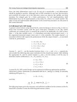
3.3.2 Automatic steerable antenna for mobile systems
A broadband circularly polarized antenna for satellite communication in X band is
presented in Fig. 11 and specified in Table 3.(b). The arrangement features and
compactness are required for highly integrated antenna arrays. It is desired to get a low-
gain antenna for mobile satellite communications with low speed of transmission. In this
system, the antennas are formed by 5 planar 4x4 arrays of antennas, which form a
truncated pyramid with a pointing capability in a wide angular range, so that among the 5
planar arrays the complete antenna can cover any of the relative positions between the
mobile system and the satellite in a practical way. The scheme of the active antenna can be
seen in Fig. 11.
As it can be observed in Fig. 11.a, the antenna terminal is a multi-beam printed antenna
shaped as a trunk pyramid capable of directing a main beam in the direction of the satellite.
The antenna steering system consists of a multi-beam feeding structure with switches that
lets combine the feed of each 4x4 arrays to form multiple beams. Switching the different 4x4
arrays, it is achieved different multiple beams and the variation of the steering direction.
Advances in Satellite Communications
178
The complete antenna consists of a Tx and Rx module that works independently in the 2
frequency bands.
The antenna has multiple beams covering the entire space to capture the satellite signal
without moving the antenna. The signal detected in each of the beams is connected to a
switch, which, by comparison, is chosen the most appropriate 4x4 array. The steering
direction of the 4x4 array can vary between a range of directions that covers a cone angle
range of 90º. To obtain the required gain and cover the indicated range, it is required around
15 beams, which can be obtained by integrating the beamforming networks with switches in
the design as presented in (Fernández et al., 2009).
a b
Fig. 11. Complete antenna structure, a) Radiating element of the 4x4 arrays, and b)
Prototype top view.
The radiating element of the 4x4 array is one 2 crossed dipoles with a stacked circular patch
as shown in Fig. 11.a and Fig. 11.b. In Fig. 12 the cross-section of the radiating element
structure is presented.
2 crossed dipoles
Balun
Ground plane
PTFE substrate NELTEC NY (ε
r
= 2.17)
Microstrip feeding network
Stacked circular patch
Foam (ε
r
= 1.07)
Ground plane
PTFE substrate NELTEC NY (ε
r
= 2.17)
PTFE substrate NELTEC NY (ε
r
= 2.17)
Foam (ε
r
= 1.07)
Foam (ε
r
= 1.07)
Fig. 12. Cross-section scheme of the radiating element.
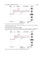
The key element of the radiating element feeding structure (Fig. 14.b) is a resonant micro-
strip feed ring that has been implemented, as well as a micro-strip 90º branch-line coupler to
obtain the desired right hand or left hand circular polarizations (RHCP or LHCP) which
ensures adequate port coupling isolation. The S-parameters in amplitude and phase of the
micro-strip feeding structure are shown in Fig. 13.a and Fig. 13.b.
Fig. 14.a depicts the S-parameters of the radiating element with the micro-strip feed
structure and they fulfill the specification, in Table 3.(b). In Fig. 14.c, the radiation pattern of
the radiating element at 7.825 GHz is shown and in Fig. 14.d the radiation pattern of the 4x4
New Antenna Array Architectures for Satellite Communications
179
arrays is presented. It is shown a maximum gain of 19.4 dBi at the center frequency band
(7.825 GHz). Copolar (CP) to crosspolar (XP) ratio is better than 17 dB and the axial ratio is
under -3dB.
a b
Fig. 13. Micro-strip feeding structure, a) Amplitude of S-parameters, and b) Phase of S-
parameters.
RHCP
LHCP
Port 1
Port 2
Port 3
Port 4
Port 6
Port 5
a
b
c
d
Fig. 14. a) S-parameters, b) Resonant ring + 90º branch-line coupler, c) radiation pattern at
7.825 GHz, and d) 4x4 array radiation pattern.
Advances in Satellite Communications
180
Parameter Value (a) Value (b) Comments
Freq. range [GHz] Rx
Tx
7.25 - 7.75
7.9 - 8.4
7.25 - 7.75
7.9 - 8.4
Microwave applications.
G/T (in Rx) [dB/K]
7 7
EIRP (in Tx) [dBW]
32 32
Beamwidth at -3dB [deg.]
4 20
Polarization
circular circular
In both, reception and
transmission.
Gain [dBi]
>28 >15
Axial ratio [dB]
< 1 <3
(a) Between ±50º.
(b) Between ±45º.
VSWR
< 1.4:1 (-15.6 dB) < 1.5:1 (-13.9 dB)
Isolation between ports
[dB]
< -17 < -15
Radiation pattern [deg.]
±35 ±90 Steering direction tilt.
Dimensions [cm]
40x40x4 20x20x15
Table 3. (a) General specifications of the steerable antenna for fixed position portable
systems , and (b) General features of the automatic steerable antenna for mobile systems.
3.4 Transmit-array-type lens antenna for terrestrial and on board receivers
Technology in satellite communications has revealed an increasing interest in novel smart
antenna designs. Phased-array based designs are basic in electronically reconfigurable
devices for satellite applications, which are more and more demanding. The strict
requirements in terms of architecture, shape and robustness are important constraints for
the development of planar lens-type devices. Regarding the usage and location, lens-type
devices are useful for either terrestrial or on board receivers, in vehicular technology. Some
clear examples are satellite communications for aircrafts preserving the fuselage
aerodynamics or for some other kind of vehicles such as trains, etc.
3.4.1 Introduction to lens-type structures
In a general view, in lens-type a particular signal is received (in our case, an electromagnetic
wave with specific features in terms of frequency, wave-front, etc.), it is processed (either
complex signal processing techniques or only phase correction tasks can be considered in
this interface), and finally, the processed signal is retransmitted.
Regarding the lens configuration, a transmit-array lens consists of three well distinguished
interfaces: the first one for signal reception, one interface for signal processing, and the last
one for processed signal re-radiation, as depicted in Fig. 15.
New Antenna Array Architectures for Satellite Communications
181
a b
Fig. 15. a) Multi-user scheme with different receivers and transmitters, and b) Adaptive
scheme with DoA determination.
These structures are intimately related to reflect-array ones, where the reception and
transmission interfaces are turned to be the same interface, with a reflection-type behavior
(Encinar & Zornoza, 2001). Although in an equal output phase configuration a transmit-
array device behavior would be similar to the one obtained with a reflect-array, the
transmit-array offers the advantage of removing the feed blockage.
In a transmission scheme, depending on the transmitter position regarding the lens, a
different steering direction is achieved and a different user is pointed. In the case of
reception, the situation is the same: the user position configures the direction of arrival,
which determines the receiver position around the lens (Padilla et al., 2010a). In adaptive
schemes, applying the proper processing algorithm to the signal received in the different
receivers around the lens, it is possible to develop an adaptive steering vector, in terms of
the desired direction of arrival.
3.4.2 Transmit-array lens architecture and design
Lens-type structures provide two fundamental advantages. First, phase error correction due
to spherical wave front coming from the feeding antenna. Fig. 16.a shows this effect. Second,
new radiation patterns configuration. Fig. 16.b depicts this fact.
a b
Fig. 16. a) Phase error correction, and b) Radiation pattern reconfiguration.
3.4.3 Electronically reconfigurable devices for active transmit-array lenses
The addition of reconfigurability on transmit-array devices requires the possibility of
controlling the phase response of the transmitted signal at each cell of the lens. Electronic
control of phase signal may be added in two different ways: First, electronic tuning of the
Advances in Satellite Communications
182
radiating element phase response (Padilla et al., 2010a): Modifications in the radiating
element circuital behavior lead to changes in phase response (arg[S
21
]). Fig. 17 shows an
electronically reconfigurable microwave patch antenna for this purpose, along with the
equivalent circuit and prototype outcomes in terms of phase.
Second, electronic tuning of phase shifters in transmission lines (Padilla et al., 2010c):
Modifications in the phase response of the phase shifters lead to corresponding changes in
phase response. Some options are applied for these devices, such as hybrid couplers, etc.
Fig. 18 shows a microwave phase shifter prototype for this purpose, along with the working
scheme and its outcomes in phase.
a b c
Fig. 17. Electronically reconfigurable antenna, a) Patch antenna prototypes, b) Equivalent
circuit, and c) Phase behavior in frequency.
a b c
Fig. 18. Electronically reconfigurable phase shifter, a) Phase shifter prototype, b) Working
scheme, and c) Phase behavior in frequency.
3.4.4 Electronically reconfigurable active transmit-array prototype
One electronically reconfigurable prototype is presented in Fig. 19 and detailed in this
section. The prototype design implies the use of microwave phase shifters according to the
design specified in section 3.4.3. This transmit-array lens prototype operates at 12 GHz.
Main specifications are provided in Table 4.
New Antenna Array Architectures for Satellite Communications
183
Parameter Value Comments
Frequency range [GHz]
12 ± 0.5 Microwave applications.
Polarization Linear In both, reception and transmission.
Directivity [dBi]
>21
Axial ratio [dB] < 1 Between ±50º elevation.
S
11
[dB] < -20
Radiation pattern [deg.]
±30 Steering direction tilt, for both H and V planes.
Feeding antenna [mm] 120 Corrugated horn linearly polarized
Phase shifters [deg.] 360 Full phase range variation.
Transmit-array elements
36 6x6 array topology.
Separation between elements 0.7λ
0
Related to the wavelength
Table 4. Main features of the electronically reconfigurable transmit-array prototype.
a b c
Fig. 19. Transmit-array core, a) Transmit-array prototype, b) Distribution networks, and c)
Phase shifter integration.
The electronically controllable steering capabilities are tested and assured for a range of ±
30ºin each main axis. An example of radiation pattern is provided in Fig. 20, for 9º tilt in one
of the main axes.
a b c
Fig. 20. a) Complete transmit-array with feeder and control circuits; and transmit-array
measurement results for 9º tilt in one axis, b) H plane, and c) 3D plot.