Recent Advances in Vibrations Analysis Part 11 doc
Bạn đang xem bản rút gọn của tài liệu. Xem và tải ngay bản đầy đủ của tài liệu tại đây (986.43 KB, 20 trang )
Torsional Vibration of Eccentric Building Systems
189
(a/b=1.0)
e= .10
e= .20
e= .30
e= .40
0.0
1.0
2.0
3.0
4.0
5.0
0.0 0.5 1.0 1.5 2.0
x
U
f
/U
o
Torsionally Flexible Torsionally Stiff
(a/b=1.0)
e= .10
e= .20
e= .30
e= .40
0.0
1.0
2.0
3.0
4.0
5.0
0.0 0.5 1.0 1.5 2.0
x
U
s
/U
o
Torsionally Flexible Torsionally Stiff
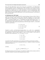
Fig. 13. Normalized displacements of the flexible and stiff edges; flat spectrum
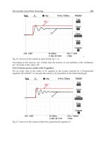
Those for the case of hyperbolic spectrum are presented in Fig. 14. The maximum
displacements of both flexible and stiff edges are calculated by modal superposition
method, using complete CQC method. These values are then normalized by
o
U the
maximum displacement in the x direction produced by the same earthquake in an
associated torsionally balanced building with stiffness and mass values similar to those of
the asymmetric building but coincident centers of mass and rigidity.
(a/b=1.0)
e= .10
e= .20
e= .30
e= .40
0.0
1.0
2.0
3.0
4.0
5.0
0.0 0.5 1.0 1.5 2.0
x
U
f
/U
o
Torsionally Flexible Torsionally Stiff
(a/b=1.0)
e= .10
e= .20
e= .30
e= .40
0.0
1.0
2.0
3.0
4.0
5.0
0.0 0.5 1.0 1.5 2.0
x
U
s
/U
o
Torsionally Flexible Torsionally Stiff
Fig. 14. Normalized displacements of the stiff and flexible edges; hyperbolic spectrum
The normalized flexible edge displacement
f
o
UUis plotted as a function of
x
for
different values of eccentricity
y
ee
and a plan aspect ratio of ab 1
in Fig. 11. In all cases
flexible edge displacement in the structure is greater than the displacement of the associated
symmetric structure. Of particular interest is the fact that there is a sharp increase in flexible
edge displacement when
x
falls below about 1.0.
It is also of interest to note that resonance between uncoupled translational and torsional
frequencies, i.e., when
x
1.0
, does not cause any significant increase in response.
Recent Advances in Vibrations Analysis
190
Frequency resonance is not, therefore, a critical issue. Plots of normalized stiff edge
displacement are shown in Fig. 13, again for different values of eccentricity
y
ee
and a plan
aspect ratio of b 1
a . Stiff edge displacement is less than 1 for
x
1.0
. For
x
1.0
, that is for torsionally flexible behaviour, stiff edge displacement starts to
increase and can be, substantially, higher than 1. The results presented in Figs. 13 and 14
clearly suggest that buildings with low torsional stiffness may experience large
displacements, causing distress in both structural and nonstructural components.
3. Torsional provisions in seismic codes as applied one-storey buildings
Most seismic building codes Formulate the design torsional moment at each storey as a
product of the storey shear and a quantity termed design eccentricity. These provisions
usually specify values of design eccentricities that are related to the static eccentricity
between the center of rigidity and the center of mass. The earthquake-induced shears are
applied through points located at the design eccentricities. A static analysis of the structure
for such shears provides the design forces in the various elements of the structure. In some
codes the design eccentricities include a multiplier on the static eccentricity to account for
possible dynamic amplification of the torsion. The design eccentricities also include an
allowance for accidental torsion. Such torsion is supposed to be induced by the rotational
component of the ground motion and by possible deviation of the centers of rigidity and
mass from their calculated positions. The design eccentricity formulae, given in building
codes, can be written in two following parts:
max
avg
Horizontal Force
F
l
o
o
r
D
i
a
p
h
r
a
g
m
L
i
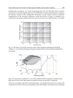
Fig. 15. Maximum and average diaphragm displacements of the structure
The first part is expressed as some magnification factor times the structural eccentricity.
This part deals with the complex nature of torsion and the effect of the simultaneous
action of the two horizontal ground disturbances.
The second term is called accidental eccentricity to account for the possible additional
torsion arising from variations in the estimates of the relative rigidities, uncertain
estimates of dead and live loads at the floor levels, addition of wall panels and
partitions; after completion of the building, variation of the stiffness with time and,
Inelastic or plastic action. The effects of possible torsional motion of the ground are also
Torsional Vibration of Eccentric Building Systems
191
considered to be included in this term. This terms in general a function of the plan
dimension of the building in the direction of the computed eccentricity.
In Iranian code, in case of structures with rigid floors in their own plan, an additional
accidental eccentricity is introduced through the effects generated by the uncertainties
associate with the distribution of the mass level and/or the spatial variation of the ground
seismic movement, (Iranian code 2800, 2005). This is considered for each design direction and
for each level and also is related to the center of mass. The accidental eccentricity is computed
with the relationship
ii
eL0.05
(31)
where
i
e is the accidental eccentricity of mass for storey i from its nominal location, applied in
the same direction at all levels;
i
L – the floor dimension perpendicular to the direction of the
seismic action. If the lateral stiffness and mass are not distributed in plan and elevation, the
accidental torsional effects may be accounted by multiplying an amplification factor
j
A as follow
j
avg
A
2
max
1.0 3.0
1.2
(32)
where
max
and
av
g
are maximum and average diaphragm displacements of the structure,
respectively, (see Fig. 15).
4. Conclusion
A study of free vibration characteristics of an eccentric one-storey structural model is
presented. It is shown in the previous sections that the significance of the coupling effect of
an eccentric system depends on the magnitude of the eccentricity between the centers of
mass and of rigidity and the relative values of the uncoupled torsional and translational
frequencies of the same system without taking the eccentricity into account. The coupling
effect for a given eccentricity is the greatest when the uncoupled torsional frequency,
,
and translational frequency,
x
of the system are equal. As the value of
x
increases, the
coupling effect decreases. For small eccentricities, the motions may reasonably be
considered uncoupled if the ratio of
x
exceeds 2.5.
In addition, it is shown that the locus of the associated center of rotation can be formulated
corresponding for a given eccentricity. Note that, for all values of eccentricity, as the value
of the uncoupled natural frequencies ratio increases the center of rotation shifts away from
the center of rigidity for the first mode and approaches the center of mass for the higher
mode. It is also shown that, the torsional behaviour of the model assembled, using our
approach, can be classified based on the nature of the instantaneous center of rotation.
It is well known that asymmetric or torsionally unbalanced buildings are vulnerable to
damage during an earthquake. Resisting elements in such buildings could experience large
displacements and distress. With eccentricity defined for one-storey buildings, the torsional
provisions or building codes can then be applied for a seismic design or such structures.
5. Acknowledgment
The author gratefully acknowledges the financial support provided by the Office of Vice
Chancellor for Research of Islamic Azad University, Kerman Branch.
Recent Advances in Vibrations Analysis
192
6. References
9-11 Research Book, (2006). Other Building Collapses, Available from
Anastassiadis, K., Athanatopoulos, A. & Makarios, T. (1998). Equivalent static eccentricities
in the simplified methods of seismic analysis of buildings, Earthquake Spectra, vol.
14, No. 1, pp.1–34.
Chandler, M. & Hutchinson, G.L. (1986). Torsional Coupling Effects in the Earthquake
Response of Asymmetric Buildings, Engineering Structures, vol. 8, pp. 222-236.
Cruz, E.F. & Chopra, A.K. (1986). Simplified Procedures for Earthquake Analysis of
Buildings, Journal of Structural Engineering, Vol. 112, pp. 461-480.
De la Llera, J.C. & Chopra, A.K. (1994). Using accidental eccentricity in code-specified static
and dynamic analysis of buildings, Earthquake Engineering and Structural Dynamics,
vol. 23, No. 7, pp. 947–967.
Dempsey, K.M. & Irvine, H.M. (1979). Envelopes of maximum seismic response for a
partially symmetric single storey building model, Earthquake Engineering and
Structural Dynamics, vol. 7, No. 2, pp. 161–180.
Earthquake Engineering ANNEXES, (2007), European Association for Earthquake
Engineering.
Fajfar P., Marusic D. & Perus I. (2005). Torsional effects in the pushover-based seismic
analysis of buildings. Journal of Earthquake Engineering, vol. 9, No. 6, pp. 831–854.
Hejal, R. & Chopra, A.K. (1989). Earthquake Analysis of a Class of Torsionally-Coupled
Buildings, Earthquake Engineering and Structural Dynamics, Vol. 18, pp. 305-323.
Iranian Code of Practice for Seismic Resistant Design of Buildings. (2005). Standard No.
2800-05, 3
rd
Edition.
Koh, T., Takase, H. & Tsugawa, T. (1969). Torsional Problems in Seismic Design of High-
Rise Buildings, Proceedings of the Fourth World Conference on Earthquake Engineering,
Santiago, Chile, vol. 4, pp. 71-87.
Kuo, Pao-Tsin. (1974). Torsional Effects in Structures Subjected to Dynamic Excitations of
the Ground, Ph.D. Thesis, Rice University.
Moghadam, A.S. & Tso, WK. (2000). Extension of Eurocode 8 torsional provisions to multi-
storey buildings, Journal of Earthquake Engineering, vol. 4, No. 1, pp. 25–41.
Newmark, N. M., (1969). Torsion in Symmetrical Buildings, Proceedings of the Fourth World
Conference on Earthquake Engineering, Vol. 2, Santiago, Chile, pp. A3-19 to A3-32.
Tabatabaei, R. & Saffari, H. (2010). Demonstration of Torsional Behaviour Using Vibration-
based Single-storey Model with Double Eccentricities, Journal of Civil Engineering,
vol. 14, No. 4., pp. 557-563.
Tanabashi, R. (1960). Non-Linear Transient Vibration of Structures, Proceedings of the Second
World Conference on Earthquake Engineering, Tokyo, Japan, vol. 2, pp. 1223.
Tso, W.K. & Dempsey, K.M. (1980). Seismic torsional provisions for dynamic eccentricity,
Earthquake Engineering and Structural Dynamics, vol. 8, No. 3, pp. 275–289.
Wilson, E. L., Der Kiureghian, A. & Bayo, E. R. (1981). A Replacement for the SRSS Method in
Seismic Analysis, Earthquake Engineering and Structural Dynamics, Vol. 9, pp. l87-l92.
10
Beam Structural Modelling in Hydroelastic
Analysis of Ultra Large Container Ships
Ivo Senjanović, Nikola Vladimir, Neven Hadžić and Marko Tomić
University of Zagreb, Faculty of Mechanical Engineering and Naval Architecture
Croatia
1. Introduction
Ultra large container ships are very sensitive to the wave load of quartering seas due to
considerably reduced torsional stiffness caused by large deck openings. As a result, their
natural frequencies can fall into the range of encounter frequencies in an ordinary sea
spectrum. Therefore, the wave induced hydroelastic response of large container ships
becomes an important issue in structural design. Mathematical hydroelastic model
incorporates structural, hydrostatic and hydrodynamic parts (Senjanović et al. 2007, 2008a,
2009b, 2010b). Beam structural model is preferable in the early design stage and for
determining global response, while for more detailed analyses 3D FEM model has to be
used. The hydroelastic analysis is performed by the modal superposition method, which
requires dry natural vibrations of the structure to be determined. For each mode dynamic
coefficients (added mass and damping) and wave load are calculated based on velocity
potential. The governing equation of ship motion in rough sea specified for the impulsive
(slamming) load as a transient problem is solved in time domain. The motion equation is
also given for the case of harmonic wave excitation (springing), which is solved in the
frequency domain.
In the chapter, methodology of the ship hydroelastic analysis is described, and position and
role of the beam structural model is explained. Beam finite element for coupled horizontal
and torsional vibrations, that includes warping of ship cross-section, is constructed. Shear
influence on both bending and torsion is taken into account. The strip element method is
used for determination of normal and shear stress flows, and stiffness moduli, i.e. shear
area, torsional modulus, shear inertia modulus (as a novelty), and warping modulus.
In the modelling of large container ships it is important to appropriately account for the
contribution of transverse bulkheads to hull stiffness and the behavior of relatively short
engine room structure. In the former case, the equivalent torsional modulus is determined
by increasing ordinary (St. Venant) value, depending on the ratio of the strain energy of a
bulkhead and corresponding hull portion. Equivalent torsional modulus of the engine room
structure is also determined utilizing the energy approach. It is assumed that a short closed
structure behaves as an open one with the contribution of decks.
Application of the beam structural model for ship hydroelastic analysis is illustrated in case
of a very large container ship. Correlation of dry natural vibrations analysis results for the
beam model with those for 3D FEM model shows very good agreement. Hydroelastic
analysis emphasizes peak values of transfer functions of displacements and sectional forces
Recent Advances in Vibrations Analysis
194
in resonances, i.e. in the case when the encounter frequency is equal to one of the natural
frequencies.
2. Methodology of ship hydroelastic analysis
A structural model, ship and cargo mass distributions and geometrical model of ship
surface have to be defined to perform ship hydroelastic analysis. At the beginning, dry
natural vibrations have to be calculated, and after that modal hydrostatic stiffness, modal
added mass, damping and modal wave load are determined. Finally, wet natural vibrations
as well as the transfer functions (RAO) for determining ship structural response to wave
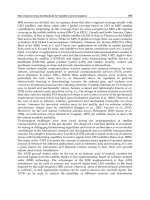
excitation are obtained (Senjanović et al. 2008a, 2009b), Fig. 1.
Fig. 1. Methodology of ship hydroelastic analysis
3. General remarks on structural model
A ship hull, as an elastic non-prismatic thin-walled girder, performs longitudinal, vertical,
horizontal and torsional vibrations. Since the cross-sectional centre of gravity and centroid,
as well as the shear centre positions are not identical, coupled longitudinal and vertical, and
horizontal and torsional vibrations occur, respectively. The shear centre in ships with large
hatch openings is located below the keel and therefore the coupling of horizontal and
torsional vibrations is extremely high. The above problem is rather complex due to
geometrical discontinuity of the hull cross-section, Fig. 2.
The accuracy of the solution depends on the reliability of stiffness parameters
determination, i.e. of bending, shear, torsional and warping moduli. The finite element
method is a powerful tool to solve the above problem in a successful way. One of the first
solutions for coupled horizontal and torsional hull vibrations, dealing with the finite
element technique, is given in (Kawai, 1973, Senjanović & Grubišić, 1991). Generalised and
improved solutions are presented in (Pedersen, 1985, Wu & Ho, 1987). In all these
references, the determination of hull stiffness is based on the classical thin-walled girder
Beam Structural Modelling in Hydroelastic Analysis of Ultra Large Container Ships
195
theory, which doesn’t give a satisfactory value for the warping modulus of the open cross-
section (Haslum & Tonnessen, 1972, Vlasov, 1961). Apart from that, the fixed values of
stiffness moduli are determined, so that the application of the beam theory for hull vibration
analysis is limited to a few lowest natural modes only. Otherwise, if the mode dependent
stiffness parameters are used the application of the beam theory can be extended up to the
tenth natural mode (Senjanović & Fan, 1989, 1992, 1997).
.
Fig. 2. Discontinuities of ship hull
4. Consistent differential equations of beam vibrations
Referring to the flexural beam theory (Timoshenko & Young, 1955, Senjanović, 1990), the
total beam deflection, w, consists of the bending deflection, w
b
, and the shear deflection, w
s
,
while the angle of cross-section rotation depends only on the former, Fig. 3
,
b
bs
w
ww w φ
x
(1)
The cross-sectional forces are the bending moment and the shear force
,
b
MEI
x
(2)
,
s
s
w
QGA
x
(3)
where E and G are the Young's and shear modulus, respectively, while I
b
and A
s
are the
moment of inertia of cross-section and shear area, respectively.
The inertia load consists of the distributed transverse load, q
i
, and the bending moment, μ
i
,
and in the case of coupled horizontal and torsional vibration is specified as
22
22
,
i
w
qm c
tt
(4)
2
2
,
ib
J
t
(5)
where m is the distributed mass, J
b
is the mass moment of inertia about z-axis, and c is the
distance between the centre of gravity and the shear centre,
GS
cz z
, Fig. 4.
Recent Advances in Vibrations Analysis
196
Fig. 3. Beam bending and torsion
Fig. 4. Cross-section of a thin-walled girder
In a similar way the total twist angle, ψ, consists of the pure twist angle, ψ
t
, and the shear
contribution, ψ
s
, while the second torsional displacement, which causes warping of cross-
section, is variation of the pure twist angle, i.e. Fig. 3 (Pavazza, 2005)
Beam Structural Modelling in Hydroelastic Analysis of Ultra Large Container Ships
197
, .
t
ts
x
(6)
The cross-sectional forces include the pure torsional torque, T
t
, warping bimoment, B
w
, and
additional torque due to restrained warping, T
w
,
tt
TGI
(7)
,
ww
BEI
x
(8)
,
s
ws
TGI
x
(9)
where I
t
, I
w
and I
s
are the torsional modulus, warping modulus and shear inertia modulus,
respectively.
The inertia load consists of the distributed torque, μ
ti
, and the bimoment, b
i
, presented in the
following form:
22
22
,
ti t
w
Jmc
tt
(10)
2
2
,
iw
bJ
t
(11)
where J
t
is the mass polar moment of inertia about the shear centre, and J
w
is the mass
bimoment of inertia with respect to the warping centre, Fig. 4.
Considering the equilibrium of a beam differential element, one can write for flexural
vibrations
,
i
M
Q μ
x
(12)
,
i
Q
x
(13)
and for torsional vibrations (Pavazza, 1991)
,
w
wi
B
Tb
x
(14)
.
tw
ti
TT
μμ
xx
(15)
The above equations can be reduced to two coupled partial differential equations as follows.
Substituting Eqs. (2) and (3) into (12) yields
Recent Advances in Vibrations Analysis
198
22
22
.
sb b
ss
wEI J
xGAxGAt
(16)
By inserting Eqs. (3) and (4) into (13) leads to
42 4 4 3
42 22 4 2
.
bb
bb
ss
qEI mJ
EI m J m mc
x t GA x t GA t x t x
(17)
In a similar way, substituting Eqs. (8) and (9) into (14) yields
22
22
.
sw w
ss
EI J
xGIxGIt
(18)
By inserting Eqs. (7), (9) and (10) into (15) one finds
422 4 4 3
422 22 4 2
.
ww
wttwt
ss
EI J
w
EI GI J J J mc
xxt GIxtGItxtx
(19)
Furthermore, ψ in (17) can be split into
ts
and the later term can be expressed with (18).
Similar substitution can be done for
bs
ww w
in (19), where w
s
is given with (16). Thus,
taking into account that
/
b
wx
and
/
t
x
, Eqs. (17) and (19) after integration
per x read
42 4 4
42 22 4
244
2224
bb bbbb
bb
ss
tw twt
ss
ww EIwmJw
EI m J m
xt GAxtGAt
EI J
mc q
tGIxtGIt
(20)
422 4
422 22
42 4 4
42 224
.
ttt wt
wttwt
s
wt b b b b b
sss
EI
EI GI J J J
xxt GIxt
JwEIwJw
mc
GI t t GA x t GA t
(21)
After solving Eqs. (20) and (21) the total deflection and twist angle are obtained by
employing (16) and (18), i.e.
22
22
bbb b
bsb
ss
EI w J w
ww w w ft
GA x GA t
(22)
22
22
wtw t
tst
ss
EI J
g
t
GI x GI t
(23)
where f(t) and g(t) are integration functions, which depend on initial conditions.
The main purpose of developing differential equations of vibrations (20) and (21) is to get
insight into their constitution, position and role of the stiffness and mass parameters, and
Beam Structural Modelling in Hydroelastic Analysis of Ultra Large Container Ships
199
coupling, which is realized through the inertia terms. If the pure torque T
t
is excluded from
the above theoretical consideration, it is obvious that the complete analogy between bending
and torsion exists, (Pavazza, 1991).
Application of Eqs. (20) and (21) is limited to prismatic girders. For more complex problems,
like ship hull, the finite element method is on disposal.
The shape functions of beam finite element for vibration analysis have to satisfy the
following consistency relations for harmonic vibrations obtained from Eqs. (22) and(23),
(Senjanović, 1990)
2
2
2
d
1
d
bbb
bs b
ss
JEIw
ww w w
GA GA x
(24)
2
2
2
d
1.
d
wwt
ts t
ss
JEI
GI GI x
(25)
5. Beam finite element
The properties of a finite element for the coupled horizontal and torsional vibration analysis
can be derived from the total element energy. It consists of the strain energy, the kinetic
energy, the work of the distributed external lateral load, q, and the torque, μ, and the work
of the boundary forces. Thus, according to (Senjanović, 1990, Senjanović & Grubišić, 1991),
22 2 2
2
22
22
0
22 22
22
0
1
d
2
1
2d
2
(
l
bs t t
s
tot b s w s t
l
bt
bwt
ww
EEI GA EI GI GI x
xxxxx
ww w
mJ mc J J x
txt ttxtt
qw
0
0
)d ( ) ,
l
l
w
xQwM T B
(26)
where l is the element length. Since the beam has four displacements,
,,,w
, a two-node
finite element has eight degrees of freedom, i.e. four nodal shear-bending and torsion-
warping displacements respectively, Fig. 5,
(0) (0)
(0) (0)
,
() ()
() ()
w
UV
wl l
ll
(27)
Therefore, the basic beam displacements, w
b
and ψ
t
, can be presented as the third-order
polynomials
, , 0,1,2,3,
, .
kk
bk tk
T
wa d k
x
l
(28)
Recent Advances in Vibrations Analysis
200
Furthermore, satisfying alternately the unit value for one of the nodal displacement {U} and
zero values for the remaining displacements, and doing the same for {V}, it follows that:
, , ,
, , , 1,2,3,4,
bbi ssi i
tti ssi i
wwUwwUwwU
VVVi
(29)
where w
bi
, w
si
, w
i
and ψ
ti
, ψ
si
, ψ
i
are the shape functions specified below by employing
relations (24) and (25)
, ,
, ,
kkk
bi ik si ik i ik
kkk
ti ik si ik i ik
wa wb wc
def
(30)
2
2
60 32
43 12 23
1
6032
12
26 0 6
ik
αβ α α
β
αβl αα βl αα βl α l
a
β
αα
αα β
β
αβl αα βl α l
(31)
Fig. 5. Beam finite elemet
Beam Structural Modelling in Hydroelastic Analysis of Ultra Large Container Ships
201
002
113
22
33
12
16
1
1,
iii
iii
ii
ii
b α a
β
a
b α a
β
a
b α a
b α a
(32)
ik ik ik
cab i k, 1,2,3,4, 0,1,2,3
(33)
2
2
1,
bb
ss
JEI
GA GA l
(34)
Constitution of torsional matrices
ik
d
,
ik
e
and
ik
f
is the same as
ik
a
,
ik
b
and
ik
c
, but parameters α and β have to be exchanged with
2
2
1,
ww
ss
JEI
GI GI l
(35)
according to (25). By substituting Eqs. (29) (26) one obtains
0
11
,
0
22
T
T TT
bs sb st
tot
ws t ts tw
Uk U UmmU qU PU
E
VkkV mm VRV
VV
(36)
where, assuming constant values of the element properties,
2
2
22
00
dd
d
d
dd
dd dd
ll
bj sj
si
bi
bs
bs
ww
w
w
kEI xGA x
xx xx
– bending-shear stiffness matrix,
2
2
22
00
dd
d
d
dd
dd dd
ll
tj sj
si
ti
ws
ws
kEI xGI x
xx xx
– warping-shear stiffness matrix,
0
d
d
d
dd
l
tj
ti
t
t
kGI x
xx
– torsion stiffness matrix,
00
d
d
dd
dd
ll
bj
bi
ij b
sb
w
w
mmwwxJ x
xx
– shear-bending mass matrix,
00
d
d
dd
dd
ll
tj
ti
tij w
tw
mJ xJ x
xx
– torsion-warping mass matrix,
0
d,
l
T
ij
st ts st
mmcwxmm
– shear-torsion mass matrix,
0
0
d–shear load vector,
d–torsion load vector,
,1,2,3,4.
l
j
l
j
qqwx
x
ij
(37)
Recent Advances in Vibrations Analysis
202
The vectors {P} and {R} in Eq. (36) represent the shear-bending and torsion-warping nodal
forces, respectively,
(0) (0)
(0) (0)
,
() ()
() ()
w
w
QT
MB
PR
Ql Tl
M
lBl
(38)
The above matrices are specified in Appendix A, as well as the load vectors for linearly
distributed loads along the finite element, i.e.
01 0 1
,.qq q
(39)
The total element energy has to be at its minimum. Satisfying the relevant conditions
0, 0
tot tot
EE
UV
(40)
and employing Lagrange equations of motion, the finite element equation yields
,
q
fk m f
(41)
where
,,
0
,.
0
q
bs sb st
ws t ts tw
PqU
ff
RV
kmm
km
kk mm
(42)
It is obvious that coupling between the bending and torsion occurs through the mass matrix
only, i.e. by the coupling matrices [m]
st
and [m]
ts
.
6. Contribution of transverse bulkheads to the hull stiffness
This problem for container ships is extensively analyzed in (Senjanović et al., 2008b),
where torsional modulus of ship cross-section is increased proportionally to the ratio of
bulkhead strain energy and strain energy of corresponding hull portion. The bulkhead is
considered as an orthotropic plate with very strong stool (Szilard, 2004). Bulkhead strain
energy is determined for the given warping of cross-section as a boundary condition. The
warping causes bulkhead screwing and bending. Here, only the review of the final results
is presented. Bulkhead deflection (axial displacement) is given by the following formula,
Fig. 6:
2
2
,12,
y
zz
uyz y z d
bH H
(43)
Beam Structural Modelling in Hydroelastic Analysis of Ultra Large Container Ships
203
where H is the ship height, b is one half of bulkhead breadth, d is the distance of warping
centre from double bottom neutral line, y and z are transverse and vertical coordinates,
respectively, and
is the variation of twist angle.
Fig. 6. Shape of bulkhead deformation
The bulkhead grillage strain energy includes vertical and horizontal bending with
contraction and torsion (Senjanović et al., 2008b).
33
2
2
1 116 32 8 143
1
1 35 105 75 75
gyzyzt
HbHb Hb
UiiiiiE
bH
(44)
where i
y
, i
z
and i
t
are the average moments of inertia of cross-section and torsional modulus
per unit breadth, respectively. The stool strain energy is comprised of the bending, shear
and torsional contributions
22
2
2
3
12 9
72 1
10 1
sb sb st
s
s
hI I bI
h
UE
bbA
(45)
where I
sb
, A
s
and I
st
are the moment of inertia of cross-section, shear area and torsional
modulus, respectively. Quantity h is the stool distance from the inner bottom, Fig. 7.
Fig. 7. Longitudinal section of container ship hold
Recent Advances in Vibrations Analysis
204
The equivalent torsional modulus yields, Fig. 7
2
10
41
1, ,
g
s
tt
t
UU
C
a
IIC
lIl E
(46)
where a is the web height of bulkhead girders (frame spacing), l
0
is the bulkhead spacing,
10
lla
is the net length, and C is the energy coefficient.
7. Contribution of engine room structure to the hull stiffness
Ultra Large Container Ships are characterized by relatively short engine room structure with
length of about a half of ship breadth. Its complex deformation is illustrated in a case of a
7800 TEU container ship, Fig. 8. The deck shear deformation is predominant, while hold
transverse bulkhead stool is exposed to bending. Due to shortness of the engine room, its
transverse bulkheads are skewed but somewhat less pronounced than warping of the hold
bulkheads. Warping of the transom is negligible, and that is an important fact when
specifying boundary conditions in vibration analysis.
Fig. 8. Deformation of 7800 TEU container ship aft structure
7.1 Stiffness of engine room structure
A short engine room structure can be considered either as a closed segment with relevant
stiffness or as an open segment with increased stiffness due to deck contribution (Pedersen,
1985). The latter simulation in fact gives results which agree better with 3D FEM results,
than the former one (Pedersen, 1983). Deck contribution to hull stiffness can be determined
by energy approach, as it is done in the case of transverse bulkheads (Senjanović et al.,
2008b). Such a beam model is consistent at global level of energy balance, and that is
sufficient for application in ship hydroelastic analysis, where proper natural frequencies and
mode shapes of dry hull are required.
In the case of short engine room, torsion induces distortion of cross-section while hull
bending is negligible. Solution of that complex problem is described here by employing the
energy balance approach and concept of the effective stiffness due to reason of simplicity. A
Beam Structural Modelling in Hydroelastic Analysis of Ultra Large Container Ships
205
closed hull segment is considered as open one with deck influence. For that purpose let us
determine deck strain energy. All quantities related to closed and open cross-section are
designated by
.
and
.
, respectively
As it can be seen in Fig. 8, the upper deck is exposed to large deformation, while the double
bottom in-plane deformation is quite small. The relative axial displacement of the internal
upper deck boundaries, with respect to double bottom, is result of their warping
DB DBt
UU U w w
(47)
It causes deck in-plane (membrane) deformation. The problem can be solved in an
approximate analytical way by considering deck as a beam. Its horizontal anti-symmetric
deflection consists of pure bending and shear contribution, Fig. 9. The former is assumed in
the form
2
3,
2
bb
yy
uU
bb
(48)
which satisfies relevant boundary conditions:
00
b
u
and
00
b
u
, where
b
U
is the
boundary bending deflection. Shear deflection depends on bending deflection
d
d
2
2
2
21 ,
b
sb
yu
EI a
uU
GA y b b
(49)
where the internal deck cross-section area, 2Aat
, its moment of inertia,
3
2
3
Iat
, and the
relation
21E ν G
, are taken into account, Fig. 9. Total deflection is obtained by
summing up its constitutive parts, Eqs. (48) and (49). Relation between total boundary
deflection and the bending boundary deflection reads
2
121
b
a
UU
b
(50)
Fig. 9. Deck deformation and double bottom rotation, a)-bird view, b)-lateral view
Recent Advances in Vibrations Analysis
206
The total internal deck strain energy consists of the bending and shear contributions
dd
dd
dd
22
2
1
2
11
22
bb
bs
bb
uu
EEI
y
GA
y
yy
(51)
By substituting Eqs. (48) and (49) into (51), one finds
32
2
1
41 1 21
b
aa
E ν Gt ν U
bb
(52)
Finally, by taking into account Eqs. (47) and (50), yields
3
2
2
1
2
41
121
DBt
a
ν Gt
b
Eww
ψ
a
ν
b
(53)
On the other hand, total energy of the closed hull segment can be obtained by summing up
energy of open segment and the deck strain energy, i.e.
1tot w t μ
EEEEE
(54)
where
ddd
11
, , .
22
aaa
wwttttμ x
aaa
EBψ xE Tψ xE μψ x
(55)
Within a short span 2a, constant value of
t
ψ
(as for deck) can be assumed, so that second
term in Eq. (26) by inserting
t
T
from Eqs. (7), leads to
2
.
ttt
EGIa
ψ
(56)
t
E and
1
E
in (54) can be unified into one term since both depend on
2
t
ψ
2
1ttt
EEGaIψ
(57)
where
1
1,
tt
t
E
ICIC
E
(58a, b)
t
I
is the effective torsional modulus which includes both open cross-section and deck
effects.
Engine room structure is designed in such a way that the hold double skin continuity is
ensured and necessary decks are inserted between the double skins. Strain energy is derived
for the first (main) deck and for the others it can be assumed that their strain energy is
Beam Structural Modelling in Hydroelastic Analysis of Ultra Large Container Ships
207
proportional to the deck plating volume, V, and linearly increasing deformation with the
deck distance from inner bottom, h, Fig. 9, since the double bottom is much stiffer than
decks. In that way the coefficient C, Eq. (58b), by employing (53) and (56), reads
3
2
1
2
41
121
DB
i
t
t
a
ν twwk
E
b
C
E
a
ν Ia
b
(59)
where
2
11
.
ii
Vh
k
Vh
(60)
In the above consideration distortion of cross-sections is not included and that is subject of
further investigation.
7.2 Torsion of segmented girder
Let us consider a girder consisted of three segments, Fig. 10. The end segments are open and
the middle one is closed, so that the girder is symmetric with respect to the z axis. Each
segment is specified in its local coordinate system. The properties of the middle and end
segments are designated by
.
and
.
, respectively. The relevant expressions for
displacements and sectional forces are listed below (Senjanović et al., 2009a, 2010a):
1
23
1
23
23
1
d
sh ch ,
d
sh ch ,
sh ch ,
,
t
p
tt p
wt wp
tpwp
ψ
A
uw w AααxAααx ψ
xl
A
TGI AααxAααx ψ
l
TGIAααxAααxEIψ
A
TGI ψ EI ψ
l
(61)
23
ch sh ,
wt w
p
BGIAαxA αxEIψ
where
p
ψ
represents particular solution of differential equation and coefficient
α
yields
.
t
w
GI
α
EI
(62)
The symbols
i
A
and
i
B
are used for the integration constants of the closed and open
segments. The girder is loaded with torque M
t
at the ends, while
0
x
μ
. The ends are fixed
against warping.
The boundary and compatibility conditions in the considered case, yield
Recent Advances in Vibrations Analysis
208
0, 0,
0, 0,
0, .
tt
ww
t
ψ a ψψa ψ
Ta T Ba B
ul Tl M
(63)
Fig. 10. Torsion of segmented girder
From the third and last conditions (63) one finds
11
, .
tt
t
t
M
aMl
AB
GI
GI
(64)
The remaining four conditions (63) lead to the system of algebraic equations (Senjanović et
al., 2010a) and its analytical solution reads:
33
2
323
, , ,
AB
B
DD
D
ABB
DDD
(65)
where
3
2
3
1ch1,
sh 1 ch ,
1sh sh ch,
ch ch sh sh .
tt
A
t
ttt
B
tt
tt
B
t
tt
MI
D βl
G
I
MII
D αa βl
GII
MI
α
D αa
β
l αa
GI β
DIααa βlIβαa βl
(66)
8. Numerical procedure for vibration analysis
A thin-walled girder is modelled with a set of beam finite elements. Their assemblage in the
global coordinate system, performed in the standard way, results in the matrix equation of
motion, which may be extended by the damping forces