Vibration Analysis and Control New Trends and Developments Part 1 pot
Bạn đang xem bản rút gọn của tài liệu. Xem và tải ngay bản đầy đủ của tài liệu tại đây (1.86 MB, 25 trang )
VIBRATION ANALYSIS AND
CONTROL – NEW TRENDS
AND DEVELOPMENTS
Edited by Francisco Beltrán-Carbajal
Vibration Analysis and Control – New Trends and Developments
Edited by Francisco Beltrán-Carbajal
Published by InTech
Janeza Trdine 9, 51000 Rijeka, Croatia
Copyright © 2011 InTech
All chapters are Open Access articles distributed under the Creative Commons
Non Commercial Share Alike Attribution 3.0 license, which permits to copy,
distribute, transmit, and adapt the work in any medium, so long as the original
work is properly cited. After this work has been published by InTech, authors
have the right to republish it, in whole or part, in any publication of which they
are the author, and to make other personal use of the work. Any republication,
referencing or personal use of the work must explicitly identify the original source.
Statements and opinions expressed in the chapters are these of the individual contributors
and not necessarily those of the editors or publisher. No responsibility is accepted
for the accuracy of information contained in the published articles. The publisher
assumes no responsibility for any damage or injury to persons or property arising out
of the use of any materials, instructions, methods or ideas contained in the book.
Publishing Process Manager Masa Vidovic
Technical Editor Teodora Smiljanic
Cover Designer Jan Hyrat
Image Copyright Igor Klimov, 2010. Used under license from Shutterstock.com
First published August, 2011
Printed in Croatia
A free online edition of this book is available at www.intechopen.com
Additional hard copies can be obtained from
Vibration Analysis and Control – New Trends and Developments,
Edited by Francisco Beltrán-Carbajal
p. cm.
ISBN 978-953-307-433-7
free online editions of InTech
Books and Journals can be found at
www.intechopen.com
Contents
Preface IX
Chapter 1 Adaptive Tuned Vibration Absorbers:
Design Principles, Concepts
and Physical Implementation 1
Philip Bonello
Chapter 2 Design of Active Vibration Absorbers
Using On-Line Estimation
of Parameters and Signals 27
Francisco Beltran-Carbajal, Gerardo Silva-Navarro,
Benjamin Vazquez-Gonzalez and Esteban Chavez-Conde
Chapter 3 Seismic Response Reduction of Eccentric
Structures Using Liquid Dampers 47
Linsheng Huo and Hongnan Li
Chapter 4 Active Control of Human-Induced Vibrations
Using a Proof-Mass Actuator 71
Iván M. Díaz
Chapter 5 Control Strategies
for Vehicle Suspension System Featuring
Magnetorheological (MR) Damper 97
Min-Sang Seong, Seung-Bok Choi and Kum-Gil Sung
Chapter 6 A Semiactive Vibration Control Design
for Suspension Systems with Mr Dampers
Hamid Reza Karimi 115
Chapter 7 Control of Nonlinear Active Vehicle Suspension
Systems Using Disturbance Observers 131
Francisco Beltran-Carbajal, Esteban Chavez-Conde,
Gerardo Silva Navarro, Benjamin Vazquez Gonzalez
and Antonio Favela Contreras
VI Contents
Chapter 8 Semi-Active Control of Civil Structures Based
on the Prediction of the Structural Response:
Integrated Design Approach 151
Kazuhiko Hiramoto, Taichi Matsuoka and Katsuaki Sunakoda
Chapter 9 Seismic Response Control Using Smart Materials 173
Sreekala R, Muthumani K, Nagesh R Iyer
Chapter 10 Whys and Wherefores of Transmissibility 197
N. M. M. Maia, A. P. V. Urgueira and R. A. B. Almeida
Chapter 11 Control Design Methodologies for Vibration
Mitigation on Wind Turbine Systems 217
Ragnar Eide and Hamid Reza Karimi
Chapter 12 Active Isolation and Damping of Vibrations for
High Precision Laser Cutting Machine 243
Andrea Tonoli, Angelo Bonfitto and Mario Silvagni
Chapter 13 Bearings Fault Detection Using Inference Tools 263
Miguel Delgado Prieto, Jordi Cusidó i Roura and
Jose Luis Romeral Martínez
Chapter 14 Vibration Analysis of an Oil Production Platform
Submitted to Dynamic Actions Induced by
Mechanical Equipment 281
José Guilherme Santos da Silva, Ana Cristina Castro
Fontenla Sieira, Luciano Rodrigues Ornelas de Lima
and Bruno Dias Rimola
Chapter 15 MIMO Vibration Control for a Flexible Rail Car Body:
Design and Experimental Validation 309
Alexander Schirrer, Martin Kozek and Jürgen Schöftner
Chapter 16 Changes in Brain Blood Flow on Frontal Cortex Depending
on Facial Vibrotactile Stimuli 337
Hisao Hiraba, Takako Sato, Satoshi Nishimura, Masaru Yamaoka,
Motoharu Inoue, Mitsuyasu Sato, Takatoshi Iida, Satoko Wada,
Tadao Fujiwara and Koichiro Ueda
Preface
This book focuses on the very important and diverse field of vibration analysis and
control. The sixteen chapters of the book written by selected experts from international
scientific community cover a wide range of interesting research topics related to original
and innovative design methodologies of passive, semi-active and active vibration control
schemes, dynamic vibration absorbers, vehicle suspension systems, structural vibration,
identification, vibration control devices, smart materials, fault detection, finite element
analysis and several other recent practical applications and theoretical studies of this
fascinating field of vibration analysis and control. The book is addressed not only to both
academic and industrial researchers and practitioners of this field, but also to
undergraduate and postgraduate engineering students and other experts and
newcomers in a variety of disciplines seeking to know more about the state of the art,
challenging open problems, innovative solution proposals and new trends and
developments in this area.
The book is organized into 16 chapters. A brief description of every chapter follows.
Chapter 1 presents the basic design principles of adaptive tuned vibration absorbers
(ATVA) and a comprehensive review of the various design concepts that have been
presented for the ATVA, including the latest innovations contributed by the author.
Chapter 2 introduces a design approach for active vibration absorption schemes in
linear mass-spring-damper mechanical systems subject to exogenous harmonic
vibrations, which can simultaneously be used for vibration attenuation and desired
reference trajectory tracking tasks. Chapter 3 deals with the seismic response control of
eccentric structures using Circular Tuned Liquid Column Dampers (CTLCD). The
optimal control parameters are derived from the motion equation of the CTLCD-
structure system and supposing that ground motion is a stochastic process. Chapter 4
presents the practical implementation of an active mass damper to cancel excessive
vertical vibrations on an in-service office floor and on an in-service footbridge. In
Chapter 5, the authors describe the formulation and experimental evaluation of
various vibration control strategies for semi-active vehicle suspension system with
magnetorheological (MR) dampers. The design of a back-stepping control scheme for
semi-active vehicle suspension systems with MR dampers is the focus of Chapter 6.
Chapter 7 proposes a robust control scheme based on the real-time estimation of
perturbation signals for active nonlinear or linear vehicle suspension systems subject
to unknown exogenous disturbances due to irregular road surfaces. Chapter 8
X Preface
introduces a methodology for semi-active control system design of civil structures. A
semi-active control law based on a one-step-ahead prediction of the seismic response
is proposed, which employs a vibration control device developed by the authors.
Chapter 9 deals with the seismic response control using smart materials. Mathematical
models are developed to predict the maximum energy dissipation capability of the
material under study. Chapter 10 presents a general overview on the transmissibility
concept for multiple degree-of-freedom systems. It is shown that the various ways in
which transmissibility can be defined and applied opens various possibilities for
research in different domains, like system identification, structural modification,
coupling analysis, damage detection, model updating, vibro-acoustic applications,
isolation and vibration attenuation. The focus of Chapter 11 is on design of control
schemes for vibration mitigation on wind turbine systems. The main control objective
of the proposed schemes is to reduce the torque variations by using speed control with
collective blade pitch adjustments. Chapter 12 focuses on the evaluation of an active
isolation and vibration damping device on the working cell of a micro-mechanical
laser center, using active electromagnetic actuators. Chapter 13 presents an overview of
multisensory inference approaches used to characterize motor ball bearings, and their
application to a set of motors with distributed fault failure. The results show that a
multivariable design contributes positively to damage monitoring of bearings. Chapter
14 investigates the dynamic behavior of an oil production platform submitted to impacts
produced by rotating machinery. A computational model is developed for the structural
system dynamic analysis. The peak acceleration values and maximum displacements
and velocities are employed to evaluate the structural model performance in terms of
human comfort, maximum tolerances of the mechanical equipment and vibration
serviceability limit states of the structural system. Chapter 15 proposes LQG and
weighted H2 MIMO control design methods for the vibration control of lightweight rail
car body structures. These designs are studied and compared to achieve vibration
reduction and passenger ride comfort improvement in a highly flexible metro rail car
body. The metro car body structure is directly actuated via locally mounted Piezo stack
actuators. Chapter 16 concludes the book, describing a study on vibrotactile stimuli on
the submandibular glands stimulated by vibration with one motor and two motors.
Finally, I would like to express my sincere gratitude to all the authors for their
excellent contributions, which I am sure will be valuable to the readers. I would also
like to thank the editorial staff at InTech for their great effort and support in the
process of edition and publication of the book.
I truly hope that this book can be useful and inspiring for contributing to the
development of technology, new academic and industrial research and many
inventions and innovations in the field of vibration analysis and control.
Francisco Beltrán Carbajal
Energy Department
Azcapotzalco Unit of the Autonomous Metropolitan University
Mexico
1
Adaptive Tuned Vibration Absorbers:
Design Principles, Concepts and
Physical Implementation
Philip Bonello
University of Manchester
United Kingdom
1. Introduction
The tuned vibration absorber (TVA) has been used for vibration control purposes in many
sectors of civil/automotive/aerospace engineering for many decades since its inception by
(Ormondroyd & Den Hartog, 1928). A tuned vibration absorber (TVA), in its most generic
form, is an auxiliary system whose parameters can be tuned to suppress the vibration of a
host structure. The auxiliary system is commonly a spring-mass-damper system (or
equivalent) and the TVA suppresses the vibration at its point of attachment to the host
structure through the application of an interface force. The tuned frequency
a
ω
of the TVA
is defined as its undamped natural frequency with its base (point of attachment) blocked.
The TVA can be used in two distinct ways, resulting in different optimal tuning criteria and
design requirements (von Flotow et al., 1994):
a. It can be tuned to suppress (dampen) the modal contribution from a specific troublesome
natural frequency
s
Ω
of the host structure over a wide band of excitation frequencies.
b. It can be tuned to suppress (neutralise) the vibration at a specific troublesome excitation
frequency
ω
, in which case it acts like a notch filter.
When used for application (a), the TVA referred to as a “tuned mass damper” (TMD).
a
ω
is
optimally tuned to a value slightly lower than that of the targeted mode
s
Ω
and an optimal
level of damping needs to be designed into the absorber. When used for application (b), the
TVA is referred to as a “tuned vibration neutraliser” (TVN) (Brennan, 1997, Kidner &
Brennan, 1999) or “undamped TVA”. The optimal tuning condition is in this case is
a
ω
ω
=
and the TVN suppresses the vibration over a very narrow bandwidth centred at the tuned
frequency. Total suppression of the vibration at this frequency is achieved when there is no
damping in the TVN.
Deviation from the tuned condition (mistuning) degrades the performance of either variant
of the TVA (von Flotow et al., 1994) and it can be shown that a mistuned vibration
neutraliser could actually increase the vibration of its host structure (Brennan, 1997). To
avoid mistuning, smart or adaptive tunable vibration absorbers (ATVAs) have been
developed. Such devices are capable of retuning themselves in real time. Adaptive
technology is especially important in the case of the TVN since the low damping
requirement in the spring element can raise the host structure vibration to dangerous levels
Vibration Analysis and Control – New Trends and Developments
2
in the mistuned condition. In this case, mistuning can occur either due to a drift in the
forcing frequency or due to a drift in tuned frequency caused by environmental factors (e.g.
temperature change). Hence, a TVN needs to be adaptive to be practically useful.
At the heart of an ATVA is a means for adjusting the tuned frequency
a
ω
in real time.
This is frequently done through the variation of the effective mechanical stiffness of the
ATVA, although other means are possible. Whatever the retuning method used, the
device should be tunable over an adequate range of frequencies, and the adjustment
should be rapid and with minimum power requirement. The device must also be cheap
and easy to manufacture. To maximise vibration attenuation, the retuning mechanism
should add as little as possible to the redundant mass of the device and, in the case of the
neutraliser, have a low structural damping (Brennan, 1997). The technical challenge is to
design an adaptive device with such attributes.
This chapter continues with a quantitative illustration of the basic design principles of
both variants of the TVA. It will then present a comprehensive review of the various
design concepts that have been presented for the ATVA, including the latest innovations
contributed by the author. This section will cover the use of piezoelectric actuators, shape-
memory alloys and servo-actuators within the smart structure of the ATVA. Control
algorithms and their implementation through MATLAB
®
with SIMULINK
®
will also be
discussed.
2. Basic design principles of TVA
With reference to Fig. 1a, the above-defined frequency
a
ω
coincides exactly with the lowest
anti-resonance frequency of the attachment point receptance frequency response function
(FRF) of the undamped “free-body” TVA structure,
(
)
AA A
rYF
ω
= , where
A
Y
and
F
are
complex amplitudes of
A
y
and the interface force
(
)
f
t , for harmonic vibration at circular
frequency
ω
. It is for this reason that, for the TVN, the condition
a
ω
ω
=
defines optimal
tuning. For excitation frequencies
ω
below the first non-zero resonance frequency
m
ω
of
(
)
AA
r
ω
, the absorber can be represented by the equivalent two-degree-of-freedom model
shown in Fig. 1b (Bonello & Groves, 2009). Fig. 1b shows that the absorber mass
a
m
is split
into an effective mass
,ae
ff
a
mRm
=
and a redundant mass
(
)
,
1
ared a
mRm=− . The latter mass
simply adds to the host structure. The effective part of the absorber is the single-degree-of-
freedom system constituted by mass
,ae
ff
m , the spring of stiffness
2
,aaae
ff
km
ω
= and a
damping element. In the case of a TMD, where damping is deliberately designed into the
device, it is preferable to represent it by viscous damper of frequency-independent
coefficient
a
c
. In the case of a TVN, where the damping is an unwanted inherent feature of
the spring element, it is best represented by a structural damping mechanism of loss factor
a
η
, for which the equivalent viscous damping coefficient is
aa
k
η
ω
. The method for
deriving the equivalent two-degree-freedom is detailed in Section 4.1.
2.1 Tuned mass damper
The purpose of the TMD is to dampen a particular resonance peak of the FRF
(
)
AP
r
ω
connecting the response at A to an external force
(
)
p
ft applied to the host structure at some
arbitrary point P. It is useful for applications where the excitation has a broad frequency
spectrum containing the targeted mode. The damping in the original host structure (i.e. the
Adaptive Tuned Vibration Absorbers: Design Principles, Concepts and Physical Implementation
3
structure prior to the addition of the TMD) is commonly assumed to be negligible relative to
that introduced by the TMD. Suppose the TMD is targeted at the s
th
mode of the original
host structure. Let
s
Ω
be the frequency of this mode and
()
s
A
ψ
denote the value of the
corresponding mass-normalised mode-shape at the degree of freedom being targeted (e.g.
the vertical displacement at A in Fig. 1). Then, from standard modal theory (Ewins, 1984),
the contribution of the targeted mode to the dynamics of the original host structure at the
targeted degree of freedom can be represented as the simple mass-spring system of mass
() ()
{
}
2
1
ss
AA
M
ψ
= and stiffness
() ()
2
ss
s
A
A
KM
Ω
= (see Fig. 2(a)). The dynamics of the original host
structure at the targeted degree of freedom can be accurately modelled in this form for
excitation frequencies
ω
in the vicinity of
s
Ω
, where the targeted mode is dominant.
Addition of the TMD in Fig. 1b to the system in Fig. 2(a) results in the system in Fig. 2(b).
Notice that original host structure modal mass
()
s
A
M needs to be readjusted to
()
,
s
ared
A
Mm+ ,
to account for the addition of the redundant absorber mass to the host structure. The
harmonic analysis of the systems in Figs. 2(a,b) (i.e. analysis with
{
}
j
Re e
t
PP
fF
ω
= ) then
gives a modal approximation of
(
)
AP
r
ω
, denoted by
()
()
s
AP
r
ω
, which is accurate for
frequencies
ω
in the vicinity of
s
Ω
.
Fig. 1. Generic TVA
Fig. 2. Dynamic modal model of the host structure without/with TMD for frequencies
ω
in
the vicinity of
s
Ω
(
)
s
A
K
a
y
(
)
reda
s
A
mM
,
+
(
)
()
()
tf
P
s
A
s
P
ψ
ψ
a
k
a
c
effa
m
,
A
y
()
s
A
M
()
s
A
K
A
y
(
)
()
()
tf
P
s
A
s
P
ψ
ψ
(a) Host structure
(b) Host structure with TMD
Vibration Analysis and Control – New Trends and Developments
4
()
()
s
AP
r
ω
can be dampened by adapting the harmonic analysis in (Den Hartog, 1956) to the
system in Fig. 2(b). The optimal tuning condition is found to be:
1
1
opt
a
s
ω
Ω
μ
=
′
+
(1)
where
() ()
{
}
,
ss
ss ared
AA
MMm
ΩΩ
′
=+
,
()
{
}
,,
s
ae
ff
a red
A
mMm
μ
=+ (2)
The viscous damping coefficient is given by:
,
2
aaae
ff
a
cm
ζ
ω
=
(3)
The optimal value of the viscous damping ratio
a
ζ
is given by (Den Hartog, 1956):
()
3
3
81
opt
a
μ
ζ
μ
=
+
(4)
The optimisation of the modulus of
()
()
s
AP
r
ω
is illustrated in Fig. 3. The introduction of the
TMD splits the original host structure resonance peak into two peaks separated by an anti-
resonance. Points M and N are referred to as the ‘fixed points’ since, for given
μ
and
a
ω
,
the function
()
()
s
AP
r
ω
of the modified structure passes through them regardless of the value
of
a
ζ
. The optimal tuning condition of eq. (1) ensures that the fixed points are level with
each other (this is the case illustrated in Fig. 3). With this condition in place, the optimal
damping condition of eq. (4) ensures that the peaks of
()
()
s
AP
r
ω
coincide as closely as
possible with the fixed points. The height of these optimised peaks is approximately
inversely proportional to
μ
.
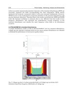
As an illustration of the effect of a TMD on a multimodal (i.e. continuous) system, consider a
TMD attached to the tip of a cantilever and tuned to attenuate its second flexural mode (Fig.
4). The cantilever OA is of length 1m and made of steel (Young Modulus 200 GN/m
2
,
density 7850 kg/m
2
) of circular section with diameter 3cm.
Assuming an Euler-Bernoulli beam model, an eigenvalue analysis yields
()
2
2
Ωπ
= 132.8
Hz,
()
2
1.387
A
M = kg. The mass ratio
μ
is taken as 2%. For simplicity, the TMD is assumed to
have no redundant mass. The TMD parameters were computed according to the above
formulae. The receptances
(
)
A
PAP
rYF
ω
= of the system with and without the TMD were
evaluated using the Dynamic Stiffness Method (Bonello & Brennan, 2001) and shown in Fig.
5, where the dampening of the targeted resonance is clearly evident.
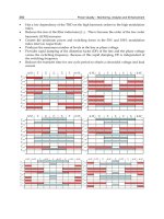
Fig. 6 illustrates the effect of mistuning i.e. deviation from the tuned condition of eq. (1). The
stiffness
a
k of the TMD was varied such that it was mistuned by 10% i.e.
a
ω
was set to
1.1
opt
a
ω
, with
a
c kept the same as the optimal case of Fig. 5 (considering eqs. (3) and (4), this
means that
a
ζ
of the mistuned case in Fig. 6 is not
opt
a
ζ
). It is clear from Fig. 6 that a slight
mistuning produces significant deterioration of the TMD performance.
Adaptive Tuned Vibration Absorbers: Design Principles, Concepts and Physical Implementation
5
0.8 0.85 0.9 0.95 1 1.05 1.1 1.15 1.2
0
10
20
30
40
50
Fig. 3. Effect of damping on the modal approximation of the attachment point FRF (case
shown is for the tuned condition, eq. (1), with
0.02
μ
=
Fig. 4. TMD attached to a cantilever
0 50 100 150 200 250 300 350 400
10
-6
10
-4
10
-2
Fig. 5. Effect of TMD targeted against the second flexural mode of cantilever in Figure 4:
original system (dashed line); with TMD (solid line)
a
k
a
c
effa
m
,
{
}
t
Pp
Ff
ω
j
eRe=
O
A
P
A
y
0.4m
0.6m
()
AP
r
ω
(m/N)
(
)
2
ω
π
(Hz)
0
=
a
ζ
()
(
)
ω
s
AP
r
s
Ω
ω
′
a
ω
ω
=
M
N
No TMD
()
()
()
⎟
⎟
⎠
⎞
⎜
⎜
⎝
⎛
×
s
A
s
P
s
A
K
ψ
ψ
opt
aa
ζ
ζ
=
opt
aa
ζ
ζ
2
=
opt
aa
ζ
ζ
5.0
=
Vibration Analysis and Control – New Trends and Developments
6
0 50 100 150 200 250 300 350 400
10
-6
10
-4
10
-2
Fig. 6. Effect of a mistuned TMD on cantilever in Figure 4: TMD optimally tuned and
damped as per eqs. (1) and (4) (solid line); 10% mistuned TMD (dotted line)
Finally, it is worth mentioning that a similar effect to the TMD can be achieved through an
electrical analogue, wherein the auxiliary system is a piezoelectric shunt circuit (Park, 2002).
In such an ‘electrical’ TVA, a piezoelectric patch is bonded to the host structure and
connected across an external inductor-resistor circuit. The piezoelectric patch is used to
convert the vibration energy of the host structure into electrical energy and introduces a
capacitor effect into the circuit, turning it into an L-C-R circuit. The electrical energy is then
dissipated most efficiently as heat through the resistor when the electrical resonance
produced by the LC components is close to the frequency of the targeted mode and the
resistor has an optimum value. One major disadvantage of the electrical TVA is the
difficulty in deriving the transfer function of the modified system (on which the
optimisation is based); the difficulty increases with the complexity of the host structure. For
this reason the electrical TVA has typically been restricted to simple host structures like
cantilevers (e.g. Park, 2002). In contrast, the classical theory of the mechanical TMD is
readily applicable to any arbitrary host structure since the only host structure data it
requires are the frequency and modal mass of the targeted mode.
2.2 Tuned vibration neutraliser
The purpose of the TVN is to plant an anti-resonance in the FRF
(
)
AP
r
ω
at some particular
chosen value of the excitation frequency
ω
. Hence, the TVN is typically used for
applications where the excitation is entirely, or mainly, at a single frequency (i.e. harmonic).
For example, suppose that it is required to cancel the tip vibration of the above considered
cantilever (Fig. 4) at a frequency of 50 Hz. The optimal condition for a TVN is
a
ω
ω
=
(5)
Hence, in this example,
a
ω
is optimally set to 100
π
. Neglecting the redundant TVA mass
and assuming an effective mass of the absorber, the absorber stiffness is calculated
accordingly. The effect of the TVN is illustrated in Fig. 7, where the absorber mass is
assumed to be 2% of the total mass of the beam. It is seen that an anti-resonance is
introduced at the desired frequency, in addition to a resonance at a slightly higher
()
AP
r
ω
(m/N)
(
)
2
ω
π
(Hz)
Adaptive Tuned Vibration Absorbers: Design Principles, Concepts and Physical Implementation
7
frequency (52 Hz) (the difference between the anti-resonance and resonance frequencies is
found to increase with the effective TVN mass).
(Brennan, 1997) defines the attenuation
D provided by a TVN for harmonic excitation as the
ratio of the vibration amplitude at A without the TVN to the amplitude there with the TVN
attached and optimally tuned:
free
TVN , opt
A
A
Y
D
Y
=
(6)
In the absence of damping in the absorber
D →∞ (complete attenuation). The attenuation
degrades with increasing absorber damping
a
η
(since this reduces the depth of the anti-
resonance in Fig. 7). Also, for given absorber damping, the TVA’s attenuating capability
degrades as
,ae
ff
m is reduced. In fact, for a host structure that is a rigid machine of mass M
mounted on soft isolators, (Brennan , 1997) showed that
a
D
μ
η
≈
(7)
where
(
)
,,ae
ff
ared
mMm
μ
=+ (8)
Deviation from the optimally tuned condition
a
ω
ω
=
(mistuning) can occur due to a change
in the excitation frequency (e.g. a change in operating speed of rotating machinery). It is
evident from Fig. 7 that even a slight mistuning will drastically degrade the performance of
the TVN. In fact, as can be seen in Fig. 7, if the excitation frequency drifts above
a
ω
then the
vibration neutraliser actually increases the vibration of its host structure due to the extra
resonance it introduced into the system. This extra resonance is itself made more
pronounced by the low damping requirement.
0 50 100 150 200 250 300 350 400
10
-6
10
-4
10
-2
Fig. 7. Effect of TVN tuned to an excitation frequency of 50Hz on the cantilever in Fig. 4:
original system (dashed line); with TVN (solid line)
(
)
2
ω
π
(Hz)
()
AP
r
ω
(m/N)
a
ω
ω
=
Vibration Analysis and Control – New Trends and Developments
8
3. Adaptive tuned vibration absorbers – an overview
“Tuning” a TVA involves making the appropriate adjustment of
a
ω
and this is done
through an adjustment in one or more properties of the TVA structure. Mistuning is avoided
through the use of adaptive (or “smart”) tuneable vibration absorbers (ATVAs) which can
automatically perform the necessary adjustment in real time (von Flotow et al., 1994,
Brennan et al., 2004a). As demonstrated in the previous section, mistuning is a far more
serious issue for the TVN, since the requirement for low absorber damping can raise the
host structure vibration to dangerous levels in the mistuned condition. It is for this reason
that adaptive technology has been mainly developed in the context of the TVN.
The ATVAs
considered in the remainder of the chapter will therefore exclusively be vibration neutralisers
.
In the context of the TVN, adaptive tuning of the device involves maintaining the condition
a
ω
ω
= in the presence of variable conditions (typically a time-varying excitation frequency
ω
, in which case the antiresonance in Fig. 7 is shifted in real time along the frequency axis,
in accordance to the current value of the excitation frequency). The challenge for ATVA
designers is to produce a device with the following attributes:
i.
low structural damping;
ii.
any actuating mechanism to retune the device should add as little as possible to the
redundant mass;
iii.
the device should be tuneable over a wide range of frequencies;
iv.
retuning should be rapid and with minimum power requirement;
v.
the device should be cheap and easy to design and manufacture.
Various design concepts for ATVAs have been proposed (von Flotow et al., 1994, Brennan et
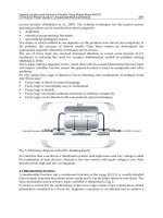
al., 2004a). One early variable stiffness element used in a vibration absorber was described
in (Longbottom et al., 1990). A mass was sandwiched between a pair of pneumatic rubber
bellows (Fig. 8) and the stiffness was adjusted by changing the air pressure inside the
bellows. Further work on this device by (Long et al., 1998) resulted in a means of
automatically adjusting the stiffness. However, the high amount of damping introduced by
the rubber bellows was a major disadvantage.
Fig. 8. Pneumatic rubber bellows ATVA (Brennan et al., 2004b)
Adaptive Tuned Vibration Absorbers: Design Principles, Concepts and Physical Implementation
9
One recent strategy for adaptation, by (Rustighi et al., 2005), was to utilise the variation with
temperature of the Young Modulus of a beam-like ATVA made of a shape memory alloy
(SMA) conductor (Fig. 9). The SMA wire formed a double cantilever, projecting from either
side of the central attachment point to the host structure. The ATVA stiffness was controlled
by adjusting the current through the wire. Despite being strong in attributes (i), (ii) and (v)
above, this device could only achieve a maximum variation of around 20% in tuned
frequency, taking as long as 2 minutes with a 9A current to do so (Brennan et al., 2004a,
Rustighi et al., 2005).
Fig. 9. Shape memory alloy ATVA (Rustighi et al., 2005)
Another recent approach, by (Bonello et al., 2005) was to utilise a mass-spring ATVA in
which the stiffness element was composed of parallel curved beams in longitudinal
compression (Fig. 10). The longitudinal stiffness was controlled by adjusting the curvature
through piezo-ceramic actuators bonded to the beams. This device was capable of very
rapid tuning over a frequency range 36-56 Hz (56% variation). However, this design concept
was inherently limited to low frequency applications as a result of inertia effects in the
curved beams (Bonello et al., 2005).
Other works have focused on the use of a beam-like ATVA controlled through servo-
actuation. This concept remains the best approach for applications requiring a wide tuning
frequency range (Carneal et al., 2004). Figs. 11-15 show various such ATVA designs. The
“moveable-supports” ATVA in Fig. 11 was patented by (Hong & Ryu, 1985). It consisted of a
beam with a mass attached to its centre and supports that could be moved relative to each
other, thereby altering
a
ω
.
(Brennan, 2000) performed a theoretical study of the tuning frequency characteristics of the
designs in Figs. 12, 13. In Fig. 12, the ATVA beam is composed of two beams and the
effective stiffness of the ATVA is adjusted by pushing apart the two constituent beams at the
centre, thereby altering the ATVA beam cross-section. Such a device was built and tested in
(Kidner et al., 2002), where a maximum adjustment of 35% in tuned frequency was
achieved. This concept appears to provide the most rapid tuning of all beam-like designs in
Figs. 11-15 since the actuator is required to move the least distance to achieve a given change
Vibration Analysis and Control – New Trends and Developments
10
in
a
ω
. However, the actuator has to work against much larger forces and the variability in
a
ω
is clearly limited by the maximum deformation that the constituent beams can
withstand as they are being prised apart. Through elementary analysis, (Brennan, 2000)
predicted that a considerably greater tuning range is achievable through the two alternative
designs in Fig. 13 (“moveable beam” or “moveable masses”). In the “moveable beam”
approach the masses are fixed relative to the beam and the beam lengthens or shortens. This
device does not appear to have been built and would require some form of telescoping
beam. The “moveable-masses” concept is more feasible: the beam is of fixed length and
tuning is achieved by repositioning the attached masses. (Von Flotow et al., 1994) describes
devices that appear to match this latter description in operation on the Boeing Chinook
helicopter, although the details available are very sketchy.
Fig. 10. ATVA with variable-curvature piezo-actuated beams (Bonello et al., 2005)
Fig. 11. Servo-actuated beam ATVA: moveable-supports, conventional design (Hong &
Ryu, 1985)
Adaptive Tuned Vibration Absorbers: Design Principles, Concepts and Physical Implementation
11
In all devices of Figs. 11-13, the actuator is a permanently redundant mass that degrades the
attenuating capacity of the ATVA (eq. (7, 8)). This limitation was overcome by (Carneal et al.,
2004) who improved the “moveable-supports” concept of (Hong & Ryu, 1985) by
incorporating the actuator into the central mass supported by the beam (Fig. 14). This
necessitated the use of a “V-Type” undercarriage. The design of this undercarriage (and the
one used in Fig. 11) clearly warrants careful consideration. It should be sufficiently rigid so as
to avoid introducing unwanted dynamics that would interfere with ATVA operation.
Moreover, it needs to be as light as possible to minimise the redundant mass. A far simpler
approach would be to utilise a moveable-masses ATVA with actuators incorporated into the
masses, as illustrated in Fig. 15, where the device simply attaches directly to the host structure
at its centre. Such a novel device was proposed by (Bonello & Groves, 2009). Apart from the
constructional simplicity, this concept was shown to provide superior ATVA performance.
Another important contribution of (Bonello & Groves, 2009) was the derivation of the
effective mass and tuned frequency characteristics of the moveable-supports and moveable-
masses ATVA. This enables the designer to quantify their expected performance for any
given application. The derivation of the effective mass of the beam-like ATVAs in Figs. 11-15
requires the derivation of their equivalent two-degree-of-freedom model (Fig. 1b). Such
analysis is very important when one considers that, for the devices in Fig. 11-15 (with the
possible exception of Fig. 12), the effective mass proportion
R will vary as the ATVA is
retuned. Although (Carneal et al., 2004) describe their actuator-incorporated mass (Fig. 14)
as the “active mass” of the absorber, its degree of activity is actually dependent on the
setting of the ATVA. The same can be said of the moveable-masses concept (Fig. 15). With
the supports or masses fully retracted in Figs. 14 and 15, the attached masses clearly become
entirely redundant and the effective mass proportion
R in Fig. 1b is then entirely contributed
by the beam itself. This means that, as the ATVA retunes itself, the attenuation it provides
will vary due to the consequent variation in
μ
(eqs. (7, 8)). Hence, the knowledge of an
“effective mass characteristic” of a moveable-supports or moveable-masses ATVA is
important since it would allow the designer to quantify the expected attenuation provided
by an ATVA over a range of frequencies for any given application.
4. ATVA analysis
The aims of this section are two-fold: (i) to illustrate the derivation of the effective mass and
tuned frequency characteristics of moveable-supports and moveable-masses ATVAs (Figs.
14 and 15); (ii) to illustrate the physical implementation and testing of the beam-like ATVA
with actuator-incorporated moveable masses (Fig. 15). This latter covers the adaptation logic
control. The material in this section is based on the work in (Bonello & Groves, 2009), from
which further details can be obtained.
4.1 Effective mass and tuned frequency characteristics
Fig. 16 shows the two alternative types of ATVA considered. It shall be assumed that the
beam supports of the device in Fig. 16b are simple supports. Let A denote the point/points
of attachment of the beam to the host structure and B denote the point/points of attachment
of the mass/masses. The aim of the following analysis is the determination of the fractional
change in tuned frequency
a
ω
and the variation of the effective mass proportion R (Fig. 1b)
as the setting
xxL
=
of the actual systems in Fig. 16 is varied. Hence, for this purpose,
damping can be omitted from the analysis without loss of accuracy.
Vibration Analysis and Control – New Trends and Developments
12
Fig. 12. Servo-actuated beam-like ATVA: adjustable beam-cross-section ATVA (Brennan,
2000, Kidner et al., 2002)
Fig. 13. Servo-actuated beam-like ATVA: moveable-beam or moveable-masses ATVA
(Brennan, 2000)
Fig. 14. Servo-actuated beam-like ATVA: moveable supports, “V-Type” design ATVA
(Carneal et al., 2004)
Adaptive Tuned Vibration Absorbers: Design Principles, Concepts and Physical Implementation
13
Fig. 15. Servo-actuated beam-like ATVA: actuator-incorporated moveable masses ATVA
(Bonello & Groves, 2009)
Fig. 16. Free-body schematics of two alternative designs for an actuator-incorporated mass
ATVA
In either case the system will be regarded as comprising a beam acted upon by: (i) the
reaction forces from the lumped mass attachments at B; (ii) the reaction force from the host.
If the latter force is
()
{
}
j
Re e
t
ft F
ω
= , then the response at any point Q on the beam is
()
{
}
j
Re e
t
yt Y
ω
=
. Following the analysis in (Bonello & Groves, 2009), the expression for
the receptance of the TVA at its point of attachment to the structure is:
()
() () () ()
()
{}
()
{}
2
2
1
22
22
2
2
1
22 2
22
3,5,
1
11
1
11
A
AA
b
AA BB BA AB
k
K
B
B
k
k
Y
r
F
m
ω
ω
ω
βω σσωβω βω σσωβω
ωω
φ
ωσσω σωφ
ωω
=
⎡⎤
−
⎣⎦
==
⎧ ⎫
⎪ ⎪
⎪ ⎪
⎡⎤ ⎡⎤
⎪ ⎪
⎡
⎤⎡⎤
−+ +− +−+ −+
⎢⎥ ⎢⎥
⎣
⎦⎣⎦
⎪ ⎪
⎣⎦ ⎣⎦
⎨ ⎬
⎡⎤
⎪ ⎪
⎢⎥
⎪ ⎪
⎡⎤
−+− −
⎢⎥
⎣⎦
⎪ ⎪
−
⎢⎥
⎪ ⎪
⎣⎦
⎩ ⎭
∑
(9)
A
B
B
(
)
tf
B
A A
(
)
2tf
()
2tf
L
2
x2
L
2
x2
(a) Moveable masses
(b) Moveable supports (‘V’-t
y
pe)