Organic Light Emitting Diode Material Process and Devices Part 8 potx
Bạn đang xem bản rút gọn của tài liệu. Xem và tải ngay bản đầy đủ của tài liệu tại đây (1.93 MB, 25 trang )
Organic Light Emitting Diode – Material, Process and Devices
166
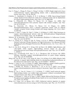
Fig. 4. a) Current/voltage, b) luminescence/voltage and c) efficiency characteristics of
ITO/TPD
(30nm)
/Alq
3
(50, 75nm)
/Al with and without iPrCS
It could be supposed that notwithstanding the iPrCS is an insulator, it seems to enhance the
hole injection thus improving a hole-electron balance in OLED and makes the tunneling
injection in OLED.
2.2 Polycarbonate (PC)
The PC is a rigid, transparent and amorphous material with high Tg 140-155
o
C. It possesses
excellent dielectric and optical characteristics. The possibility of usage of PC as buffer layer
in OLED with ITO/PC/TPD/Alq
3
/Al structure was investigated. The PC layers with
thicknesses of 9, 12 and 17 nm were deposited via spin-coating from 0.1%, 0.2% and 0.3%
dichlorethane solutions. The basic characteristics of OLED structure with different thickness
of PC buffer layer are presented in Fig.5. It was found that inserting of 9 nm buffer layer in
OLED devices decreased the turn on voltage from 12.5 to 8 V, and increased the current
density from 10 to 24 mA/cm
2
and the luminescence from 220 to 650 cd/m
2
(at 17.5 V)
compared to the reference structure. Further increasing of the thickness of PC buffer layer
decreases the current density and the luminescence, and shift the turn on voltage toward
higher values (Fig.5b), as was established with iPrCS.
0 5 10 15 20 25 30
0
25
50
75
100
with iPrCS (13 nm)
Alq
3
(50 nm)
Alq
3
(75 nm)
without iPrCS
Alq
3
(50 nm)
Alq
3
(75 nm)
Current Density (mA/cm
2
)
Voltage (V)
a
5 10152025
0
250
500
750
with iPrCS (13 nm)
Alq
3
(50 nm)
Alq
3
(75 nm)
without iPrCS
Alq
3
(50 nm)
Alq
3
(75 nm)
Voltage (V)
Luminescence (cd/m
2
)
b
0255075
0
1
2
3
with iPrCS (13 nm)
Alq
3
(50 nm)
Alq
3
(75 nm)
without iPrCS
Alq
3
(50 nm)
Alq
3
(75 nm)
Current Density (mA/cm
2
)
Electroluminescent
efficiency (cd/A)
Organic Light Emitting Diodes Based on Novel Zn and Al Complexes
167
Fig. 5. Current/voltage (5a), luminescence/voltage (5b) and efficiency (5c) for inset in
legends structures.
The best characteristics – the lowest turn-on voltage, the highest luminescence and the
highest efficiency showed OLED with 9 nm PC buffer layer. It should be noted that the
efficiency of the device with 9 nm buffer layer is more than 2x higher than that of the
reference device. Similar improvement of characteristics of device with 1 nm Teflon buffer
layer was observed by Qiu et al. (2002). They supposed that the Teflon layer acts as a stable
fence to impede indium diffusion from ITO electrode into the TPD layer and thus enhances
the device stability.
It could be supposed that the improvement of EL performance of devices with buffer layers
of iPrCS and PC has just the same genesis. Although these compounds are insulators, they
seem to enhance the hole injection from anode by tunneling. Thus improving a hole-electron
balances in OLED.
We also made attempts to use the PC and iPrCS polymers as a matrix for TPD. In this cases
the turn on voltages of the devices with composite buffer layers were lower than that with
only PC and iPrCS buffer layers, but unfortunatly the luminescence of the devices were
significantly reduced and unsatisfactory. The last one makes the application of PC and
iPrCS polymers irrelevant as matrix of TPD for OLEDs.
0 5 10 15 20 25 30
0
10
20
30
40
50
60
PC
(9)
/ TPD
(30)
/ Alq
3
(50)
PC
(12)
/ TPD
(30)
/ Alq
3
(50)
PC
(17)
/ TPD
(30)
/ Alq
3
(50)
TPD
(30)
/ Alq
3
(50)
Current Density (mA/cm
2
)
Voltage (V)
a
0 5 10 15 20 25 30
0
250
500
750
PC
(9)
/ TPD
(30)
/ Alq
3
(50)
PC
(12)
/ TPD
(30)
/ Alq
3
(50)
PC
(17)
/ TPD
(30)
/ Alq
3
(50)
TPD
(30)
/ Alq
3
(50)
Voltage (V)
Luminance (cd/m
2
)
b
02550
0
1
2
3
4
5
PC
(10)
/ TPD
(30)
/ Alq
3
(50)
PC
(15)
/ TPD
(30)
/ Alq
3
(50)
PC
(20)
/ TPD
(30)
/ Alq
3
(50)
TPD
(30)
/ Alq
3
(50)
Current Density (mA/cm
2
)
Electroluminescent
efficiency (cd/A)
c
Organic Light Emitting Diode – Material, Process and Devices
168
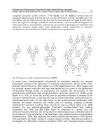
On the results obtained could be concluded that iPrCS and polycarbonate can be
successfully use as buffer layers for obtaining of OLED with good performance.
Further devices with the typical hole transporting layers poly(9-vinylcarbazole) (PVK) and
N, N’-bis(3-methylphenyl)-N, N’-diphenylbenzidine (TPD) were studied. That’s why we
investigated the influence of single layer of PVK, TPD, PVK as a buffer layer with respect to
TPD and composite layer of PVK:TPD on the performance of the device structure
ITO/HTL/Alq
3
/Al. The HTL (31 nm) of PVK and PVK:TPD composite films (10wt% TPD
relatively PVK in 0.75% dichloroethane solutions) were deposited by spin-coating.
Fig. 6. a) Current/voltage, b) luminescence/voltage and c) efficiency characteristics of
devices shown in set.
The optimal I/V, L/V and efficiency characteristics of the devices ITO/PVK/Alq
3
/Al,
ITO/PVK/TPD/Alq
3
/Al, ITO/(PVK:TPD)/Alq
3
/Al and ITO/TPD/Alq
3
/Al as reference
are presented in Fig.6. It is seen that the I/V and L/V curves for ITO/(PVK:TPD)/Alq
3
/Al
and ITO/TPD/Alq
3
/Al structures are almost identical. But it was established that due to the
well known trend of TPD thin films to crystallization, the lifetime of the reference device
with TPD only is many times shorter than that with composite layer of PVK:TPD. The
device structure with only PVK and ITO/PVK/TPD/Alq
3
/Al, showed a decrease in the
current density, luminescence and efficiency compared to the reference device. Obviously,
0 5 10 15 20 25 30 35
0
10
20
30
40
50
60
70
ITO/TPD
(30)
/Alq
3
(75)
ITO/PVK
(30)
/Alq
3(75)
ITO/PVK
(30)
/TPD
(30)
/Alq
3(75)
ITO/(PVK:TPD)
(31)
/Alq
3(75)
Current Density (mA/cm
2
)
Volta
g
e
(
V
)
a
0 5 10 15 20 25 30 35
0
250
500
750
1000
ITO/TPD
(30)
/Alq
3(75)
ITO/PVK
(30)
/Alq
3(75)
ITO/PVK
(30)
/TPD
(30)
/Alq
3(75)
ITO/(PVK:TPD)
(31)
/Alq
3(75)
Luminescence (cd/m
2
)
Voltage (V)
b
0 5 10 15 20 25 30 35 40
0
1
2
3
Electroluminescent effic. (cd/A)
ITO/TPD
(30)
/Alq
3(75)
ITO/PVK
(30)
/Alq
3(75)
ITO/PVK
(30)
/TPD
(30)
/Alq
3(75)
ITO/(PVK:TPD)
(31)
/Alq
3(75)
Current Density (mA/cm
2
)
c
Organic Light Emitting Diodes Based on Novel Zn and Al Complexes
169
the use of PVK as HTL, or as a buffer layer in respect of TPD HTL in OLEDs is not felicitous,
because impedes the charge transfer.
It could be stressed that the devices with PVK:TPD composite layer demonstrates the best
characteristics. The involving of TPD in PVK matrix improves the current density,
luminescence and luminescent efficiency, reduces the turn-on voltage and increases the
lifetime compared to the others devices.
Fig. 7. a) Current/voltage, b) luminescence/voltage and c) efficiency characteristics of
devices ITO/iPrCS/TPD/Alq
3
/Al, ITO/PC/TPD/Alq
3
/Al, ITO/(PVK:TPD)/Alq
3
/Al and
ITO/TPD/Alq
3
/Al shown in set.
The best results obtained for four type devices with different buffer and hole transporting
layers are presented in Fig.7. It is clearly seen that inserting of buffer layer caused
decreasing of turn on voltage and increasing of current densities, luminescence and
efficiency. The best electroluminescence of 570 cd/m
2
at 17.5 V belonged to the device with
iPrCS, followed by devices with PC, TPD and PVK:TPD, respectively with 510, 380 and 350
cd/m
2
. At the same time the best efficiency of 3.3 cd/A at 37 mA/cm
2
exhibited device with
PC followed by devices with TPD (2.17 cd/A), iPrCS (1.88 cd/A) and PVK:TPD (1.73 cd/A).
A comparison of the OLED characteristics for the four devices clearly indicates that the device
performance is greatly improved when the ITO surface was covered by polymeric film.
0 5 10 15 20 25 30
0
25
50
75
100
TPD
(30nm)
/Alq
3(75 nm)
PVK:TPD/Alq
3(75 nm)
PC/TPD
(30 nm)
/Alq
3(50 nm)
iPrCS
(13nm)
/TPD/Alq
3(75 nm)
Current Density (mA/cm
2
)
Voltage (V)
a
0 5 10 15 20 25
0
250
500
750
1000
TPD
(30nm)
/Alq
3(75 nm)
PVK:TPD/Alq
3(75 nm)
PC/TPD
(30 nm)
/Alq
3(50 nm)
iPrCS
(13nm)
/TPD/Alq
3(75 nm)
Voltage (V)
Luminescence (cd/m
2
)
b
0255075
0
2
4
TPD
(30nm)
/Alq
3(75 nm)
PVK:TPD/Alq
3(75 nm)
PC/TPD
(30 nm)
/Alq
3(50 nm)
iPrCS
(13nm)
/TPD/Alq
3(75 nm)
Current Density (mA/cm
2
)
Electroluminescent efficiency (cd/A)
c
Organic Light Emitting Diode – Material, Process and Devices
170
Besides that the efficiency of the devices with composite PVK:TPD layer is not so high, this
HTL is most perspective due to the synergistic effect from properties of both components.
The incorporation of TPD with PVK offers an attractive route to combine the advantiges of
easy spin-coating formability of PVK with the better hole transporting properties of TPD.
The composite PVK:TPD layers is very reproducible, simplify the obtaining of experimental
samples and by reason of that it was used in our basic structure for the study of different
electroluminescent compounds as emitting layer in OLEDs.
The efficiency of the OLED is a complexed problem, and depends not only on the energy
levels of functional layers of the devices, but also on the interfaces between inorganic
electrodes/organic layers. We demonstrate that the thin polymeric films enable to facilitate
the transport of carriers and to improve the adhesion and morphology between ITO, and
“small” molecular organic layer.
2.3 Effect of morphology
The ITO is common known as an excellent electrode, but its morphology can has an affect
on the organic layers evaporated on ITO substrate, where the small spikes in the ITO surface
can lead to local crystallization of HTL and EL causing a bright white-spot that may increase
the leakage and instability of the device.
The surface morphology of the hole transporting and buffer layers were studied by scaning
electron microscopy (SEM) and atom force microscopy (AFM).
SEM micrographs of vaccum deposited TPD and spin-coating composite PVK:TPD hole
transporting films on PET/ITO substrates are presented in Fig.8 and Fig.9.
a) bare ITO b) ITO/TPD - as deposited c) ITO/TPD after one day
Fig. 8. SEM images of: a) bare ITO on PET substrate; b) as deposited, and c) after one day
vacuum deposited 30nm TPD layer on ITO/PET
a) ITO/PVK:TPD - as deposited b) ITO/PVK:TPD after one day
Fig. 9. SEM images of composite PVK:TPD spin-coating deposited layer on ITO/PET
Organic Light Emitting Diodes Based on Novel Zn and Al Complexes
171
The surface morphology of the developed by us composite films of PVK:TPD (Fig.9.) is very
smooth and homogeneous, without any defects and cracks, thus creating a suitable
conditions for the condensation of the next electroluminesent layer. The similar is the
surface morphology of the vacuum as-deposited TPD films on bare ITO (Fig.9b.), but after 1
day storage at ambient temperature, TPD formed an islands structure with bubbles, which is a
prerequisite for recrystallization and oxidation (Fig.8c.). At the same time the surface
morphology of PVK:TPD, layers does not show any changes after 1 day storage (Fig.9b.) –
better stability of devices with composite PVK:TPD hole transporting layer could be expected.
The results of AFM investigations are presented in Fig.10. It is shown that surface of the
commercial ITO coated PET substrates is with uniform roughness with some imperfections.
The evaporated TPD layer onto this ITO surface makes a granular structure (Fig.10. a, b).
The introducing polymer buffer layers covered the ITO pinholes, spikes and other defects,
thus leveling its surface (Fig.10. c, e, and g). The amorphous and very smooth surface of
spin-coated polymer thin films creates more suitable conditions for vacuum deposition of
TPD thin films compared to the bare ITO. As far as TPD layers deposited onto studied
buffer coatings are concerned, a quite even granular structure is observed (Fig.10. d, f, h).
Fig. 10. a) bare ITO surface onto PET substrate. b) ITO/TPD surface
Fig. 10. c) ITO/ iPrCS surface d) ITO/iPrCS/TPD surface
Fig. 10. e) ITO/ PC surface f) ITO/PC/TPD surface
400350300250200150100500
10
8
6
4
2
0
X
[
nm
]
Z[nm]
100nm
4003002001000
7
6
5
4
3
2
1
0
X
[
nm
]
Z[nm]
100nm
450400350300250200150100500
12
10
8
6
4
2
0
X
[
nm
]
Z[nm]
100nm
400350300250200150100500
8
6
4
2
0
X
[
nm
]
Z[nm]
100nm
450400350300250200150100500
16
14
12
10
8
6
4
2
0
X
[
nm
]
Z[nm]
100nm
100nm
4003002001000
16
14
12
10
8
6
4
2
0
X
[
nm
]
Z[nm]
Organic Light Emitting Diode – Material, Process and Devices
172
Fig. 10. g) ITO/ PVK surface h) ITO/PVK/TPD surface
Fig. 10. AFM images and cross-section profiles of the surfaces of a) bare ITO, b) ITO/TPD,c)
ITO/iPrCS surface, d) ITO/iPrCS/TPD surface, e) ITO/PC surface, f) ITO/PC/TPD surface,
g) ITO/PVK surface, h) ITO/PVK/TPD surface
Unlike the fast recrystalization of TPD layer deposited on bare ITO, the amorphorous and
homogeneous surface of TPD films deposited on the buffer-coated ITO was very stable. The
results obtained show that the polymer modifies successfully the film morphology, thus
preventing the recrystallization of hole transporting layer (TPD) and following emissive
layer. These results definitely have an effect on the current density and luminance
characteristics of the devices. Probably, the higher Tg of the polymers than that of the TPD,
improve the durability of HTL on Joule heat, which arises in OLED operations, thus enable
the better performance of OLED.
3. Novel Zn complexes
Many organic materials have been synthesized and extended efforts have been made to
obtain high performance electroluminescent devices. In spite of the impressive
achievements of the last decade, the problem of searching for the new effective luminescent
materials with different emission colours is still topical. Metal-chelate compounds are
known to yield broad light emission and seem to provide design freedom needed in
controlling photo-physical processes in such devices. Among these materials, Zn complexes
have been especially important because of the simplicity in synthesis procedures and wide
spectral response. Extensive research work is going on in various laboratories to synthesize
new Zn complexes containing new ligands to produce a number of novel luminescent Zn
complexes as emitters and electron transporters (Sapochak et al, 2001, 2002; Hamada et al,
1996; Sano et al, 2000; Kim et al, 2007; Rai et al, 2008). Zinc(II) bis[2-(2-hydroxyphenyl)
benzothiazole] (Zn(BTz)
2
) has been studied as an effective white light emissive and electron
transporting material in OLED. Hamada et al. (1996) reported that the device with single-
emitting layer of Zn(BTz)
2
showed a greenish white emission. Later on an efficient white-
light-emitting device were developed with electroluminescent layers of Zn(BTz)
2
doped
with red fluorescent dye of 4-dicyanomethylene-2-methyl-6-[2-(2,3,6,7,-tetrahydro-1H,5H-
benzo[i,j]quinolizin-8-yl)vinyl]-4H-pyran (DCM2) (Lim et al, 2002) or rubrene (Zheng et al,
2005; Wu et al, 2005). Recently Zhu et al. (2007) fabricated white OLED with Zn(BTz)
2
only
as emitter. The obtained white emission is composed of two parts: one is 470 nm, which
originates from exciton emission in Zn(BTz)
2
, the other is 580 nm, which originates from
exciplexes formation at the interface of TPD/Zn(BTz)
2
.
We investigated the new Zn complexes Zinc(II) [2-(2-hydroxyphenyl)benzothiazole]
acetylacetonate (AcacZnBTz) and Zinc(II) bis[2-(2-hydroxynaphtyl)benzothiazole)
100nm
4003002001000
16
14
12
10
8
6
4
2
0
X
[
nm
]
Z[nm]
100nm
4003002001000
8
7
6
5
4
3
2
1
0
X
[
nm
]
Z[nm]
Organic Light Emitting Diodes Based on Novel Zn and Al Complexes
173
(Zn(NBTz)
2
), and known Zinc(II) bis[2-(2-hydroxyphenyl)benzothiazole] (Zn(BTz)
2
)
(Tomova et al, 2008), and Zinc(II) bis(8-hydroxyquinoline) (Znq
2
) (Fig.11), synthesized by
prof. Deligeorgiev as electroluminescent and electron transporting compounds. The basic
OLED structure was PET/ITO/(PVK:TPD)/EML/Al.
AcacZnBTz Zn(NBTz)
2
Zn(BTz)
2
Znq
2
Fig. 11. The chemical structures of used Zn complexes
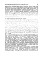
The absorption and fluorescent (PL) spectra of the complexes were taken using the Spectro-
fluorimeter Perkin Elmer MPF 44 are presented in Fig.12.
Fig. 12. Absorption and PL emission spectra of 100 nm films of Zn complexes evaporated on
glass substrate
The PL peak wavelength of Znq
2
is at 550 nm, of Zn(BTz)
2
at 486 nm, of AcacZnBTz at 490
nm. Zn(NBTz)
2
shows peak at 509 nm and shoulder at 580 nm. The data obtained for PL
peaks of Znq
2
and Zn(BTz)
2
are very closed to the results reported by Shukla & Kumar
(2010) for Znq
2
(540 nm) and by Qureshi et al. (2005) for Zn(BTz)
2
(485 nm).
The electroluminescent (EL) spectra of devices PET/ITO/(PVK:TPD)
(31 nm)
/EML
(75 nm)
/Al,
obtained at different voltages by Ocean Optics HR2000+ spectrometer are shown in Fig.13.
It was established that the EL spectra of the complexes with benzthiazole ligand were very
similar and exhibited a green electroluminescence around 525 nm. Besides the EL spectra of
all four compounds were red shifted, about 10 nm for Znq
2
and 25 – 30 nm of benzthiazole
complexes, compared to their corresponding PL spectra. Take into account the fact that the
exciton disassociates easily under the excitation of electric field than the light, red shifting of
O
O
Zn
O
N
S
H
3
C
H
3
C
S
N
O
Zn
N
S
O
S
N
O
N
S
O
Zn
N
O
Zn
N
O
300 400 500 600 700
0.0
0.5
1.0
0.0
0.5
1.0
402 nm Zn(BTz)
2
396 nm Zn(NBTz)
2
400 nm AcacZnBTz
386 nm
Znq
2
Absorption (a.u.)
Absorption Emission
Emission (a.u.)
Wavelenght (nm)
486 nm
509 and 580 nm
490 nm
550 nm
Organic Light Emitting Diode – Material, Process and Devices
174
EL spectra were quite understandable (Wu et al, 2005). The highest EL intensity showed the
devices with AcacZnBTz followed by those with Zn(BTz)
2,
Znq
2
, and Zn(NBTz)
2
.
Fig. 13. Electroluminescent spectra of OLEDs with different Zn complexes
The EL peak wavelength of the devices with Znq
2
and Zn(BTz)
2
is the same during the device
operation independantly on the working voltage, while EL peak of the devices with
AcacZnBTz moves from 493 to 524 nm with increasing the working voltage. Our results were
quite different from these obtained by Wu et al. (2005), who showed almost identical EL and
PL for Zn(BTz)
2
, and Qureshi et al. (2005) who founded broader EL than PL spectrum AFM
images of top surfaces of devices with EML of different Zn complexes are presented in Fig.14.
ITO/PVK:TPD/Zn(BTz)
2
- ITO/PVK:TPD/AcacZnBTz
ITO/PVK:TPD/Znq
2
ITO/PVK:TPD/Zn(NBTz)
2
Fig. 14. AFM images of top surfaces of devices with EML of different Zn complexes,
performed by “EasyScan 2” produced by “Nanosurf” (Switzerland) on area of 12.5 x 12.5
μm, at measurement mode “scan forward” and Scan mode from down to up.
400 500 600 700 800
0
2000
4000
6000
8000
10000
12000
554 nm Znq
2
Electroluminescent intensity (a.u.)
(nm)
12 V
14 V
16 V
18 V
20 V
22 V
24 V
400 500 600 700 800
0
2000
4000
6000
8000
10000
12000
(nm)
10 V
12 V
14 V
16 V
18 V
20 V
523 nm
Zn(BTz)
2
400 500 600 700 800
0
2000
4000
6000
8000
10000
12000
493 nm
Acac Zn(BTz)
(nm)
10 V
12 V
14 V
16 V
18 V
20 V
524 nm
400500600700800
0
2000
4000
6000
8000
1
0000
1
2000
(nm)
546 nm
12 V
14 V
16 V
18 V
20 V
22 V
24 V
Zn(NBTz)
2
524 nm
Organic Light Emitting Diodes Based on Novel Zn and Al Complexes
175
The AFM images show that evaporated Znq
2
and Zn(BTz)
2
compounds, on
PET/ITO/PVK:TPD structure, formed similar fine-textured surfaces with root mean square
(RMS) roughness respectively 6.88 nm and 4.64 nm. The AcacZnBTz layer made soft outline
ridge surface with RMS roughness 20.06 nm.
All three complexes formed smooth and even surfaces requisite for the good performance of
OLED on their base. Maybe due to the molecular structure specific of the Zn(NBTz)
2
the film
obtained from it is very flat (RMS roughness 22.82 nm), but with some acicular formations
over 150 nm on some areas. Namely these formations are а precondition for the worse EL
performance of OLED with electroluminescent layer of Zn(NBTz)
2
.
Fig. 15. a) Current/voltage and b) luminescence/voltage characteristics and c) electro-
luminescent efficiency for devices with different EML
(75nm)
and HTL of (PVK:TPD)
(31nm)
Fig.15. presents the current/voltage, luminance/voltage and efficiency characteristics of
four type identical devices with different EML. It was established that the current densities
and the luminescence decreased and the turn-on voltage of devices increased in following
sequence AcacZnBTz, Zn(BTz)
2
, Znq
2
, Zn(NBTz)
2
. Luminescence of the device with
AcacZnBTz at 15 V DC was nearly 1.5 and 3 times higher than those by Zn(BTz)
2
and Znq
2
,
respectively (Fig.15b). At the same time the electroluminescent efficiencies of the devices
with AcacZnBTz and Zn(BTz)
2
were nearly the same (around 3 cd/A) and 1. 5 and 3 times
higher than that of devices with Znq
2
and Zn(NBTz)
2
(Fig.15c).
For OLEDs with similar structures Sano et al. (2000) reported efficiency 1.39 cd/A at
luminance 100 cd/m
2
for ITO/TPD/Zn(BTz)
2
/Mg:In device, Zheng et al. (2005) - 4.05 cd/A
0 5 10 15 20 25 30
0
20
40
60
Znq
2
Zn(BTz)
2
Zn(NBTz)
2
AcacZn(BTz)
Current Density (mA/cm
2
)
Voltage (V)
a
0 5 10 15 20 25 30
0
250
500
750
1000
Znq
2
Zn(BTz)
2
Zn(NBTz)
2
AcacZn(BTz)
Voltage (V)
Luminance (cd/m
2
)
b
0255075
0
1
2
3
Znq
2
Zn(BTz)
2
Zn(NBTz)
2
AcacZn(BTz)
Current Density (mA/cm
2
)
Electroluminescent efficiency (cd/A)
c
Organic Light Emitting Diode – Material, Process and Devices
176
for doped with rubrene Zn(BTz)
2
white device at maximum luminescence 4048 cd/m
2
[10]
and Rai et al (2008) - 1.34 cd/A for ITO/NPD/Zn(Bpy)q/Al.
The results presented in this chapter show that the studied Zn complexes with the exception
of Zn(NBTz)
2
can be successfully used as emitters and electron transporting layers for
OLED. It could be stressed that the efficiency of the devices with Zn(BTz)
2
is 2.9 cd/A at
luminance 250 cd/m
2
– one of the best reported up to now in the literature for the devices
with similar structure. Besides that the devices with new Zn complexes are not optimized,
its characteristics are quite promising, especially for AcacZnBTz – the highest luminance
and the efficiency 3 cd/A in the range of 10 – 30 mA/cm
2
.
4. Aluminum bis(8-hydroxyquinoline)acetylacetonate (Alq
2
Acac) complex
Since Tang and VanSlyke (1987) had developed the first organic light-emitting diode
(OLED), Aluminum tris(8-hydroxyquinoline) (Alq
3
) has been one of the most successful
organic materials ever used as the emitting, electron-transport and host material layer in
OLEDs. Numerous derivatives on Alq
3
structure were prepared and their optical and
semiconductor properties were tested. Alq complex BAlq (bis(2-methyl-8-quinolinate)4-
phenyl-phenolate) was first introduced by Kodak group as a blue-emitting material and
mostly used as hole blocking layer (Kwong et al., 2002) and as a blue emitter (Kwong et al.,
2005; Iwama et al., 2006; Yu et al., 2007). Hopkins and coworkers (1996) have also obtained
blue shifted emission from Alq
3
derivate via introduction of the strong electron
withdrawing –SO
2
NR
2
group at C-5 of the 8-hydroxyquinoline ligand.
Azenbacher group investigated the role of 5-(arylethynyl)- (Pohl & Anzenbacher, 2005),
5-(aryl)- (Pohl et al., 2004; Montes et al., 2004, 2006; Pérez-Bolívar et al., 2006), and two C4-
aryl- (Pérez-Bolívar et al., 2010) substituents on the quinolinolate rings, in Alq
3
derivatives
and their effect on the photophysical properties and electroluminescence. Many methyl-
substituted derivatives nMeq
3
Al (Kwong et al., 2005; Sapochak et al., 2001; Kido & Iizimi,
1998), phenyl-substituted Alpq
3
(Tokito et al., 2000), soluble 5-substituted-Alq
3
derivates
(Mishra et al., 2005), aluminum complexes such as Alq
2
OR (OR=aryloxy or alkoxy ligand)
(Lim et al., 2006), have been developed and have been demonstrated to be useful emissive
materials or/and hole blocking/electron transporting materials. Ma et al. (2003) have
synthesized a new material dinuclear Aluminum 8-hydroxy-quinoline complex (DAlq
3
)
with two time higher electron mobility than that in Alq
3
.
Omar et al. (2009) synthesized and investigated new aluminum tris(8-hydroxyquinoline)
derivatives, having nitrogen functionalities at position-4 of the quinolate ligand, acting as
efficient emitters with higher luminance and external quantum efficiency than the parent
Alq
3
in an identical OLEDs. (The PL and EL emission wavelengths of the new Al complexes
can be tunes according to the electronic properties of the substituents at position-4). Bingshe
Xu et al. (2008) reported about a mixed-liquand 8-hydroxyquinoline aluminium complex
with higher electron mobility and electroluminescent efficiency compared with Alq
3
.
Herе we presented а new Al complex, aiming the development of OLED with improved
performance. The novel mixed-ligand Aluminum bis(8-hydroxyquinoline)acetylacetonate
(Alq
2
Acac) complex (Fig.16.) was synthesized and it performance as electroluminescent and
electron transporting layer for OLED was studied and compared with that of the parent
Alq
3
(Petrova et al., 2009).
To investigate the efficiency of the new Al complex as emitter, the devices
ITO/HTL/EML/Al with EML layers of Alq
2
Acac or commercial Alq
3
were fabricated.
Organic Light Emitting Diodes Based on Novel Zn and Al Complexes
177
Fig. 16. Structure of Aluminum bis(8-hydroxyquinoline)acetylacetonate (Alq
2
Acac)
Fig. 17. I/V and L/V characteristics for devices with different HTL
(31 nm)
and EL
(75 nm)
Fig. 18. Electroluminescent efficiency for devices with different HTL
(31 nm)
and EL
(75 nm)
O
O
N
O
Al
N
O
CH
3
CH
3
0 5 10 15 20 25
0.1
1
10
100
1000
0
20
40
60
cd/m
2
TPD/Alq
2
Acac
PVK:TPD/Alq
2
Acac
TPD/Alq
3
PVK:TPD/Alq
3
Current Density (mA/cm
2
)
Voltage (V)
Luminance (cd/m
2
)
b
mA/cm
2
0 1020304050
0
2
4
cd/m
2
TPD/Alq
2
Acac
PVK:TPD/Alq
2
Acac
TPD/Alq
3
PVK:TPD/Alq
3
Current Density (mA/cm
2
)
Electroluminescent effic. (cd/A)
Organic Light Emitting Diode – Material, Process and Devices
178
The current density-voltage and luminescence-voltage characteristics of the studied devices
are shown in Fig.17. The I/V curves of the devices with Alq
2
Acac were located in lower
voltage region compared to the devices with Alq
3
. The luminescence of the devices with
Alq
2
Acac is 2 times higher compared to the similar devices with Alq
3
(Fig.17). The turn-on
voltage of the devices with Alq
2
Acac is lower compared to those with Alq
3
especially in the
case with TPD hole transporting layer – nearly 2 times.
Bingshe Xu et. al. (2008) reported the electron mobilities in Alq
2
Acac can be determined to
be 2.7–4.4x10
-6
cm
2
/V.s at electric fields ranging between 1.42x10
6
and 2.40x10
6
V/cm,
which is higher than those in Alq
3
published in the literature (Huang et al., 2005; Brütting
et al., 2001).
It could be stressed that the efficiency of the devices with Alq
2
Acac are nearly 50 % higher
compared to those with Alq
3
with HTL of TPD and about 2 times higher with HTL of
PVK:TPD (Fig.18).
The ionization potential (Ip) and the electron affinity (Ea) of Alq
2
Acac and Alq
3
were
determined by cyclic voltammetry of 0.001 M solutions of compounds in C
2
H
4
Cl
2
in
presence of 0.1 M tetra-n-butylammonium hexafluorophosphate as supporting electrolyte.
Fig. 19. The energy band diagram of investigated OLEDs
They were: Ip: Alq
2
Acac 6.11 eV and Alq
3
5.97 eV; Ea: Alq
2
Acac 3.34 eV and Alq
3
3.16 eV.
The band gaps were nearly equal (Eg = 2.77 eV for Alq
2
Acac and 2.81 eV for Alq
3
), that is in
agreement with the values of 2.64 eV obtained by extrapolation of UV-Vis spectrums to
absorption edges (Fig.20). As can be seen in Fig.19, both barriers for electrons and for holes
are higher at Alq
2
Acac compared with thеse of Alq
3
, which explains the better efficiency of
devices with Alq
2
Acac.
Our results for the devices ITO/TPD
(30nm)
/Alq
2
Acac (or Alq
3
)
(75nm)
/Al are 5.6 cd/A for
Alq
2
Acac and 3.9 cd/A for Alq
3
. Alq
2
Acac based devices performed higher current density
and emission efficiency. It indicates that the electron transport of Alq
2
Acac is better than
that of Alq
3
after the electron injection from the cathode to the electron transport layer,
which is in a good agreement with the actual measurement of mobility. Probably, the
molecular mixed-liqand structure of Alq
2
Acac promoted higher electroluminescence
efficiency and led to subsequent increase of the device performance.
4.1 Luminescence studies
The absorption and the fluorescent emission spectra of thin layers Alq
2
Acac and Alq
3
are
nearly identical see Fig.20. Both complexes emit green light with maximum at 520nm.
Organic Light Emitting Diodes Based on Novel Zn and Al Complexes
179
Fig. 20. Absorption and fluorescent emission spectra of Alq
2
Acac and Alq
3
100 nm layers
deposited on glass substrates.
The EL spectra observed at different voltages from the two studied devices
ITO/PVK:TPD/Alq
2
Acac and ITO/PVK:TPD/Alq
3
were shown in Fig.21.
Fig. 21. EL spectra at different voltages of OLED structures ITO/PVK:TPD/Alq
2
Acac and
ITO/PVK:TPD/Alq
3
.
The electroluminescence of both devices was similar to the fluorescence. It was established
that the Alq
2
Acac emission peak was located at 531 nm, quite close to that of Alq
3
at 525 nm,
respectively. As far as concerned to the intensity of the peaks, those of the devices with
Alq
2
Acac emitter layers are nearly 2 times higher than that with Alq
3
at the identical
experiments. It could be take note of that EL spectra of the two devices (Fig.21a and Fig.21b)
are nearly identical like the PL spectra of the corresponding Alq
2
Acac and Alq
3
thin solid
films (Fig.20). It is possible, the included in Al complex acetylacetonate ligand does not
participate in the π π * transition of quinolinolato ligands responsible for light emission.
400 500 600 700 800
0
1000
2000
3000
4000
5000
6000
7000
8000
9000
10000
11000
12000
Alq
3
12 V
14 V
16 V
18 V
20 V
22 V
24 V
Electroluminescent Intensity (a.u.)
(nm)
400 500 600 700 800
1000
2000
3000
4000
5000
6000
7000
8000
9000
10000
11000
12000
Electroluminescent Intensity (a.u.)
(nm)
Alq
2
acac
12 V
14 V
16 V
18 V
20 V
22 V
24 V
300350400450500550600650
0.0
0.3
0.6
0.9
0.0
0.3
0.6
0.9
Alq
3
spectra
Alq
2
Acac spectra
Wavelength (nm)
Absorption (a.u.)
Emission (a.u.)
Organic Light Emitting Diode – Material, Process and Devices
180
Obviously the replacement of a quinolinolato ligand with an acetylacetonate ligand couldn’t
tune the emission colour but increase the efficiency of the devices.
4.2 Morphology
The performance of OLEDs is greatly influenced by the morphology of organic thin layers.
This is due to the important role that morphology of the active organic thin films play in the
phenomena that led to light emission. As was mention above, strong recrystalization of the
TPD layers after 1 day storage at ambient temperature was established. At the some time
composite PVK:TPD films remain stable - very smooth and homogeneous without any
defects and cracks.
In this part of the work, the surface roughness of organic thin films was investigated via
White Light Interferometer (WLI) MicroXAM S/N 8038. The surface relief profiles of the
hole transporting layers of TPD and composite films of PVK:TPD were presented in Fig.22,
while the surface profiles of the next electroluminesent layers of Alq
2
Acac deposited onto
corresponding HTL were presented in Fig.23. The root mean squire (RMS) roughness
observed of the different samples are: 2.00±0.15 nm for TPD, 1.65±0.14 nm for PVK:TPD,
2.45±0.13 nm for TPD/Alq
2
Acac, and 2.05±0.17 nm for PVK:TPD/Alq
2
Acac. The RMS of
PVK:TPD/Alq
3
determined from the
surface profile shown in Fig.24 is 2.20±0.22. Both
electroluminescent layers of Alq
3
and Alq
2
Acac deposited on the composite films PVK:TPD
show flat and amorphous surfaces which is a prerequisite for good performance of devices.
a) PET/ITO/TPD b) PET/ITO/PVK:TPD
Fig. 22. WLI of: OLED HTL layers of TPD (as deposited), and composite PVK:TPD
The similar is the surface morphology of the vacuum as deposited TPD films. Quantitative
values indicate that the flexible acetylacetonate moieties help the formatting of more
uniform and planarizing molecular film. The PVK:TPD, PVK:TPD/Alq
3
and
PVK:TPD/Alq
2
Acac layers does not show any changes after 1 day storage – better stability
of devices with composite PVK:TPD hole transporting layer could be expected.
In conclusion, must to give prominence that the molecular structure of Alq
2
Acac not only
promoted the formation of very quantitative thin films, contributing to the high device
efficiency, as well as the replacement of quinolinolato ligand with acetylacetonate ligand
couldn’t tune the emission colour. Alq
3
is still one of the widely-used fundamental materials
as emitter and electron transporting layer in OLED due to its excellent thermal stability,
Organic Light Emitting Diodes Based on Novel Zn and Al Complexes
181
high fluorescence efficiency and relatively good electron mobility. The results obtained
show that the change of one 8-hydroxyquinoline ligand with acetylacetonate ligand in the
novel complex improves substantially the performance of OLED. Besides that the devices
with new Al complex are not optimized, its characteristics are quite promising.
a) PET/ITO/TPD/Alq
2
Acac b) PET/ITO/PVK:TPD/Alq
2
Acac
Fig. 23. WLI surface of electroluminescent Alq
2
Acac layer deposited onto HTLs.
Fig. 24. WLI surface of electroluminescent Alq
3
layer deposited on PET/ITO/PVK:TPD
HTL.
5. Bathocuproine as hole-blocking layer
In conventional PVK:TPD/Alq
3
/Al OLEDs, the mobility of holes in PVK:TPD is much
larger than that of the electrons in Alq
3
. Also, the injection barrier of the anode/PVK:TPD
interface is lower than that of the cathode/Alq
3
interface, resulting in the imbalance of holes
and electrons in the emitting zone (Brütting at al., 2001; Mück et al., 2000). Therefore, it is
necessary to confine the redundant holes in the emitting layer in order to increase the
efficiency. Many effective methods have been reported to reduce the hole mobility and
improve the balance of holes and electrons in the emitting layer (Troadec et al., 2002;
Masumoto & Mori, 2008; Mori et al., 2008; Kim et al., 2005).
Organic Light Emitting Diode – Material, Process and Devices
182
400 500 600 700 800
0
2000
4000
6000
8000
10000
12000
Electroluminescent Intensity (a.u.)
10 V
12 V
14 V
16 V
18 V
20 V
22 V
24 V
26 V
, nm
2,9-Dimethyl-4,7-diphenyl-1,10-phenanthroline (bathocuproine, BCP) was used in OLED
and organic photovoltaic cell because of its multiple role as hole blocking (Adamovich et al.,
2003; Kim et al., 2008; Tomova et al., 2008, 2010), exciton-blocking layer (Zhang et al., 2005;
Tripathi et al., 2008; Mori & Kato, 2007; Wu et al., 2003), electron transporting and buffer
layer (Wang et al., 2006), or in combination with NPB in (NPB/BCP)
n
(n-number of layers)
as hole-trapping layer ( Shi et al., 2006).
In this work we present our results concerning the role of bathocuproine as hole blocking
layer in OLED structure: ITO/HTL/EML/HBL/ETL/M. HTL of composite PVK:TPD was
spin-coated layer, and HBL, EML and ETL –were thermal evaporated films of BCP and Alq
3
.
The absorption and emission photoluminescence spectrums of evaporated layers of BCP,
Alq
3
and BCP/Alq
3
, measured by Spectrofluorimeter Perkin Elmer MPF 44 are presented
in Fig.25.
Fig. 25. Absorption and PL emission spectra of thin evaporated films (100 nm) of BCP, Alq3
and BCP/Alq
3
Fig. 26. EL spectra of the ITO/PVK:TPD
(31nm)
/Alq
3
(40 nm)
/BCP
(1 nm)
/Alq
3
(15 nm)
device at
different voltages, were measured on Ocean Optics HR2000+ spectrometer
200 300 400 500 600 700
0.0
0.5
1.0
0.0
0.5
1.0
BCP/Alq
3
BCP
Alq
3
Wavelength (nm)
Emission (a.u.)
Absorption (a.u.)
Organic Light Emitting Diodes Based on Novel Zn and Al Complexes
183
It is seen that the PL spectra of Alq
3
and BCP/Alq
3
layers are nearly identical with PL peak
wavelength at 520 nm. Therefore in these wave length ranges BCP neither absorbs nor
radiates and observed fluorescent emission originates from Alq
3
only
.
Besides, the EL
spectra (Fig.26) observed from the ITO/PVK:TPD/Alq
3 (40)
/BCP
(1)
/Alq
3 (15)
device at
different voltages are quite similar to the fluorescent spectrum of the corresponding Alq
3
film. The emission peaks were located at 525 nm and are at the same position as the peak of
Alq
3
based structure (presented earlier in this chapter), which also is an evidence that BCP
do not participate in the light emission.
Fig.27 presents the current density (Fig.27a) and luminance (Fig.27b) versus voltage, and
current and power efficiency versus luminance (Fig.27c) characteristics of the devices
ITO/PVK:TPD/Alq
3 (40 nm)
/BCP
(x nm)
/Alq
3 (15 nm)
/Al, where x is 0; 1; 5 and 15 nm. The I-V
curves (Fig.27a) show that insertion of BCP layer decreases the current density and shifts the
threshold voltage from 11V to 17V for devices without and with 15 nm BCP. The
luminescence initially increases from 750cd/m
2
to 1100cd/m
2
for device with 1 nm BCP and
then decreases with increasing the thickness of BCP (Fig.27b).
Fig. 27. Current-voltage (I-V) (2a), luminescence-voltage (L-V) (2b), current and power
efficiency (2c) curves for devices shown in set
Fig.28 presents the driving voltage and the efficiency at luminance 100 and 200 cd/m
2
in
dependence on the thickness of BCP. It is seen that despite of the higher voltage of the
0 5 10 15 20 25 30
0
10
20
30
40
50
(PVK:TPD/Alq
3
(60 nm)/BCP(15 nm)
(PVK:TPD)/Alq
3
(40 nm)/BCP(x nm)/Alq
3
(15 nm)
15
5
1
0
Current Density (mA/cm
2
)
Voltage (V)
a
0 5 10 15 20 25 30
0
250
500
750
1000
1250
1500
1750
(PVK:TPD/Alq
3
(60 nm)/BCP(15 nm)
(PVK:TPD)/Alq
3
(40 nm)/BCP(x nm)/Alq
3
(15 nm)
15
5
1
0
Voltage (V)
Luminance (cd/m
2
)
b
0 500 1000 1500
1
10
1
10
c
Cd/A lm/W
15
5
1
0
Power efficiency (lm/W)
(PVK:TPD)/Alq
3
(60 nm)/BCP(15 nm)
(PVK:TPD)/Alq
3
(40 nm)/BCP(x nm)/Alq
3
(15 nm)
Luminance (cd/m
2
)
Current efficiency (cd/A)
Organic Light Emitting Diode – Material, Process and Devices
184
devices with BCP their current efficiency significantly increase from 3.7 to 9.6 cd/A, and
power efficiency increase from 0.87 to 1.46 lm/W (at 100 cd/m
2
) for devices without and
with 15 nm BCP layer. The beneficial influence of BCP is not only related to the magnitude
of the efficiency but also to the broader luminance range which could be seen in Fig.27c.
The best characteristics - the lower threshold and working voltage, the highest luminescence
and 2 times increased efficiency from 3.7 to 7.1 cd/A and from 0.87 to 1.75 lm/W at 100
cd/m
2
demonstrates device with 1 nm BCP layer compared to the device without BCP.
Fig. 28. Current and power efficiency, and voltage v/s thickness of BCP
At first sight increasing of the luminance for device with very thin BCP layer looks
strangely, but it can be explain with the island structure of thin layer. On one hand the
islands are enough great to confine the holes (due to the high hole barrier from 0.7 eV at the
EML/HBL (Fig.29) thus improving the recombination at the EML/BCP interface, but on the
other hand they aren’t enough dense to cause materially decreasing of the electric field yet.
Fig. 29. The energy band diagram of the investigated OLEDs.
Khalifa et al. (2004) estimated that the diffusion length of holes in BCP probably lies in the
15-20 nm range. Thicker BCP layers lead to a decrease of luminance which could be
attributed to a decrease of electron density arriving at the Alq
3
/BCP interface and thus to a
degradation of the carrier balance. The comparison of the results obtained for devices with
BCP/Alq
3
and BCP only, at equal thicknesses of BCP, shows more than 2 times higher
051015
2.5
5.0
7.5
10.0
10
15
20
25
Efficiency cd/A lm/W
at 100 cd/m
2
at 200 cd/m
2
Efficiency
Thickness BCP (nm)
Voltage
at 100 cd/m
2
at 200 cd/m
2
Voltage (V)
PVK
Alq
3
BCP
- - - - -
2.3 - 2.5
3.0
2.9
ITO
4.8
4.1
Al
5.4 - 5.6
5.7
6.4
- - - - -
(
+
)
(
-
)
h
+
e
-
+
TPD
HTL
EL
HBL
Alq
3
ETL
Organic Light Emitting Diodes Based on Novel Zn and Al Complexes
185
current efficiency and 70-100% higher power efficiency at approximately equal luminance
for the devices with Alq
3
as ETL. Obviously this is due to the higher with 0.1 eV LUMO
level of BCP than that of Alq
3
, which make the electron injection from Al to BCP more
difficult.
The crystallization of organic films in OLEDs is one factor reducing the device performance.
It is well known that, because of molecular migration, an evaporated BCP film is
immediately crystallized after deposition (Masumoto & Mori, 2008). That’s why we
investigated the surface relief profiles and roughness, of consequently deposited layers of
the device with best performance PVK:TPD/Alq
3 (40nm)
/BCP
(1nm)
/Alq
3 (15nm)
. The WLI
images presented in Fig.30 show flat and amorphous layers structure with nearly the same
roughness - RMS 2.20 ± 0.22 nm for PVK:TPD/Alq
3 (40nm)
, RMS 2.16 ± 0.34 nm for
PVK:TPD/Alq
3 (40nm)
/BCP
(1nm)
and RMS 1.89 ± 0.22 nm for PVK:TPD/Alq
3 (40nm)
/BCP
(1nm)
/Alq
3 (15nm)
. It is a prerequisite for good performance.
Fig. 30. Surface relief profiles, obtained on White Light Interferometer MicroXAM S/N 8038
of: a) PVK:TPD
(31 nm)
/Alq
3 (40 nm)
; b) PVK:TPD/Alq
3 (40 nm)
/BCP
(1 nm)
; c) PVK:TPD
(31 nm)
/Alq
3
(40 nm)
/BCP
(1 nm)
/Alq
3 (15 nm)
Becker et al. (2007) in their research of the influence of thermal annealing of BCP and Alq
3
(used as exciton blocking layers) on characteristics of organic photovoltaics were found that
BCP is more susceptible to heat and oxygen than Alq
3
. They observed that visible on a
macroscopic level crystals of BCP were appeared at temperature of 100°C while Alq
3
even at
300°C, in open air, formed only minor pinpoint crystals. In our case probably that is the
Organic Light Emitting Diode – Material, Process and Devices
186
reason causing the better performance of devices containing additional ETL of Alq
3
. OLED
with improved efficiency 4.3 cd/A more than twice that of the undoped OLED (1.8 cd/A)
by doping BCP into Alq
3
as an ETL and HBL was fabricated by Wu et al. (2003). Our results
for efficiencies from 7.2 up to 9.6 cd/A in dependence on the thickness of BCP are quite
promising.
In conclusion it can be say that BCP with its deep HOMO level (6.4 eV) is a good hole
blocking layer. The influence of HBL in confining the carriers and excitons was clearly
evidenced by a strong increase of the device efficiency. BCP offers possibilities to optimize
the architecture of the OLED thus improving significantly the performance of the devices.
The better performance of the devices with BCP could be attributed to the improved hole-
electron balance.
6. Conclusions
On the basis of synthesized novel Zn and Al complexes, successfully chosen functional
layers and improved architecture experimental OLEDs with very good characteristics are
developed. The results reveal a new approach to the design and preparation of high-
performance luminescence materials for the development of full-color flexible displays, new
class energy-saving solid state light sources.
7. References
Adamovich V., Cordero S., Djurovich P., Tamayo A., Thompson M., Andrade B., and Forrest
S. (2003), New charge-carrier blocking materials for high efficiency OLEDs, Organic
Electronics, Vol. 4, No 2-3, pp. 77-87, ISSN: 1566-1199.
Arai M., Nakaya K., Onitsuka O., Inoue T., Codama M., Tanaka M. and Tanabe H. (1997),
Passive matrix display of organic LEDs, Synth.Met., Vol. 91, No 1-3, pp. 21-25, ISSN:
0379-6779.
Baldo M., O’Brien D., You Y., Shoustikov A., Sibley S., Thomson M., and Forrest S. (1998),
Highly efficient phosphorescent emission from organic electroluminescent devices,
Nature, Vol. 395, No 6698, pp. 151-154, ISSN : 0028-0836
Becker K. (2007), Exciton Blocking Layers in Organic Photovoltaics, Cornell Center for
Materials Research.,
Berntsen A., Croonen Y., Liedenbaum C., Schoo H., Visser R, Vieggaar J., and Van de Weijer
P. (1998), Stability of polymer LEDs, Optical Materials, Vol. 9, No 1-4, pp. 125-133,
ISSN: 0925-3467.
Brütting W., Berleb S., and Mückl A. (2001), Device physics of organic light-emitting diodes
based on molecular materials, Org. Electron.,Vol. 2, No 1, pp. 1-36, ISSN: 1566-1199.
Burroughes J., Bradley D., Brown A., Marks R., Mackey K., Friend R., Burns P., Holmes A.
(1990), Light-emitting diodes based on conjugated polymers, Nature, Vol. 347, No
6293, pp. 539-541, ISSN : 0028-0836
Carter S., Angelopoulos M., Karg S., Brock P, and Scot J. (1997), Polymeric anodes for
improved polymer light-emitting diode performance, Appl. Phys. Lett., Vol. 70, No
16, pp.2067-2070, ISSN: 0021-8979.
Chan I. and Hong F. (2004), Improved performance of the single-layer and double-layer
organic light emitting diodes by nickel oxide coated indium tin oxide anode, Thin
Solid Films, Vol. 450, No 2, pp. 304- 311, ISSN: 0040-6090.
Organic Light Emitting Diodes Based on Novel Zn and Al Complexes
187
Deng Z., Ding X., Lee S., and Gambling W. (1999), Enhanced brightness and efficiency in
organic electroluminescent devices using SiO
2
buffer layers, Appl. Phys. Lett., Vol.
74, No 15, pp. 2227-2230, ISSN: 0021-8979.
Gao Y., Wang L.,.Zhang D, Duan L., Dong G., and Qiu Y. (2003),, Bright single-active layer
small-molecular organic light-emitting diodes with a polytetrafluoroethylene
barrier, Appl. Phys. Lett., Vol. 82, No 2, pp. 155-158, ISSN: 0021-8979.
Guo F.and Ma D. (2005), White organic light-emitting diodes based on tandem structures,
Appl. Phys. Lett., Vol. 87, No 17, 173510, ISSN: 0021-8979.
Hamada Y., Sano T., Fujii H., Nishio Y., Takahashi H. and Shibata K. (1996), White-Light-
Emitting Material for Organic Electroluminescent Devices, Japanese Journal of
Applied Physics, Vol. 35, No 10B, pp. L1339-L1341, ISSN: 0021-4922.
Hopkins T., Meerholz K., Shaheen S., Anderson M., Schmidt A., Kippelen B., Padias A., Hall
H , Peyghambarian N., and Armstrong R. (1996), Substituted Aluminum and Zinc
Quinolates with Blue-Shifted Absorbance/Luminescence Bands: Synthesis and
Spectroscopic, Photoluminescence, and Electroluminescence Characterization,
Chem. Mater., Vol. 8, No 2, pp 344–351, ISSN: 0897-4756
Hu W. and Matsumura M. (2002), Organic single-layer electroluminescent devices
fabricated on CuO
x
-coated indium tin oxide substrate, Appl. Phys. Lett. Vol. 81, No
5, 806, ISSN: 0021-8979.
Huang C. H., Li F., and Huang W. (2005), Introduction to Organic Light-Emitting Materials
and Devices, Fudan University Press, Shanghai.
Im H., Choo D., Kim T., Kim J., Seo J., and Kim Y. (2007), Highly efficient organic light-
emitting diodes fabricated utilizing nickel-oxide buffer layers between the anodes
and the hole transport layers, , Thin Solid Films, Vol. 515, No 12, pp. 5099-5102,
ISSN: 0040-6090.
Iwama Y., Itoh T., Mori T., and Mizutani T. (2006), Electroluminescent properties of organic
light-emitting diodes using BAlq and Alq
3
co-evaporation layer, Thin Solid Films
Vol. 499, No 1-2, pp. 364-368, ISSN: 0040-6090.
Jiang H., Zhou Y., Ooi B., Chen Y., Wee T.,. Lam Y, Huang J., and Liu S. (2000),
Improvement of organic light-emitting diodes performance by the insertion of a
Si
3
N
4
layer, Thin Solid Films,Vol. 363, No1-2, pp.28-25, ISSN: 0040-6090.
Jiang X, Zhang Z, Cao J., Khan M., Haq K., and Zhu W. (2007), White OLED with high
stability and low driving voltage based on a novel buffer layer MoO
x
, J.Phys.D:
Applied Physics, Vol. 40, N 18, 5553, ISSN: 0022-3727
Jung B., Lee J., Chu H., Do L., and Shim H. (2002), Synthesis of Novel Fluorene-Based
Poly(iminoarylene)s and Their Application to Buffer Layer in Organic Light-
Emitting Diodes, Macromolecules, Vol. 35, No 6, pp 2282–2287, ISSN 0024-9297.
Khalifa M., Vaufrey D., and Tardy J. (2004), Opposing influence of hole blocking layer and a
doped transport layer on the performance of heterostructure OLEDs, Organic
Electronics, Vol. 5, No 4, pp. 187-198, ISSN: 1566-1199.
Kido J., and MatsumotoT. (1998), Bright organic electroluminescent devices having a metal-
doped electron-injecting layer, Appl. Phys. Lett., Vol. 73, No 20, pp. 2866- 2869,
ISSN:0003-6951.
Kido J., and Iizimi Y. (1998), Fabrication of highly efficient organic electroluminescent
devices, Appl. Phys. Lett., Vol. 73, No 19, pp. 2721- 2724, ISSN 0003-6951.
Organic Light Emitting Diode – Material, Process and Devices
188
Kim Y., Park H., and Kim J. (1996), Enhanced quantum efficiency in polymer
electroluminescence devices by inserting a tunneling barrier formed by Langmuir–
Blodgett films, Appl. Phys. Lett., Vol. 69, No 5, pp. 599-602, ISSN: 0021-8979.
Kim J., Song M., Seol J., Hwang H., and Park Ch. (2005), Fabrication of Red, Green, and Blue
Organic Light-Emitting Diodes Using m-MTDATA as a Common Hole-Injection
Layer, Korean J. Chem. Eng., Vol. 22, No 4, pp. 643-647, ISSN: 0256-1115.
Kim D., Kim W., Lee B. and Kwon Y. (2007), White Organic Light-Emitting Diode Using
Blue-Light-Emitting Zn(HPB)
2
Material, Japanese Journal of Applied Physics, Vol. 46,
No. 4B, pp. 2749-2753, ISSN: 0021-4922.
Kim D., Kim W., Kim B., Lee B., and Kwon Y. (2008), Characteristics of white OLED using
Zn(phen) as a yellowish green emitting layer and BCP as a hole blocking layer,
Colloids and Surfaces A: Physicochem. Eng. Aspects, Vol 313–314, pp. 320-323, ISSN:
0927-7757.
Krag S., Scott C., Salem R, and Angelopoulos M. (1996), Increased brightness and life time
of polymer light-emitting diodes with polyaniline anodes, Synth. Met.; Vol. 80, No
2, pp. 111–117, ISSN: 0379-6779
Kwong R., Nugent M., Michalski L., Ngo T., Rajan, K. Tung Y., Weaver M., Zhou Th., Hack
M., Thompson M., Forrest S., and Brown J. (2002), High operational stability of
electrophosphorescent devices, Appl. Phys. Lett., Vol. 81, No 1, pp.162- 165, ISSN:
0021-8979.
Kwong C., Djurisic A., Choy W., Li D., Xie M., Chan W., Cheah K, Lai P., and Chui P. (2005),
Efficiency and stability of different tris(8-hydroxyquinoline) aluminium (Alq
3
)
derivatives in OLED applications, Mat. Sci. Eng. B, Vol., 116, No 1, pp. 75 -81, ISSN:
0921-5107
Legnani C., Reyes R., Cremona M., Bagatin I., and Toma H (2004), Tunable blue organic
light emitting diode based on aluminum calixarene supramolecular complex, Appl.
Phys. Lett., Vol. 85, No 1, pp. 10- 13, ISSN: 0021-8979.
Li F., Tang H., Anderegg J., and Shinar J. (1997), Fabrication and electroluminescence of
double-layered organic light-emitting diodes with the Al
2
O
3
/Al cathode, Appl.
Phys. Lett. Vol 70, No 10, pp. 1233-1236, ISSN: 0021-8979.
Lim J., Lee N., Ahn Y., Kang G. and Lee C. (2002), White-light-emitting devices based on
organic multilayer structure, Current Applied Physics, Vol. 2, No 4, pp. 295-298,
ISSN: 1567-1739.
Lim J., Jeong C., Lee J., Yeom G., Jeong H., Chai S., Lee I., and Lee W. (2006), Synthesis and
characteristics of bis(2,4-dimethyl-8-quinolinolato)(triphenylsilanolato)aluminum
(III): A potential hole-blocking material for the organic light-emitting diodes, J.
Organometallic Chemistry, Vol. 691, No 12, pp. 2701- 2707, ISSN: 0022-328X.
Lu H. and Yokoyama M. (2003), Enhanced emission in organic light-emitting diodes using
Ta
2
O
5
buffer layers, Solid-State Electronics, Vol. 47, No 8, pp. 1409–1412, ISSN: 0038-
1101.
Ma D., Wang G., Hu Y., Zhang Y., Wang L., Jing X., Wang F., Lee C., and Lee S. (2003), A
dinuclear aluminum 8-hydroxyquinoline complex with high electron mobility for
organic light-emitting diodes, Appl. Phys. Lett. Vol. 82, No 8, pp. 1296-1299, ISSN:
0021-8979.
Organic Light Emitting Diodes Based on Novel Zn and Al Complexes
189
Masumoto Y. and Mori T. (2008), Application of organic bathocuproine-based alloy film to
organic light-emitting diodes, Thin Solid Films, Vol. 516, No 10, pp. 3350-3356, ISSN:
0040-6090
Meyer J., Hamwi S., Bülow T., Johannes H.,. Riedl T, and Kowalsky W. (2007), Highly
efficient simplified organic light emitting diodes, Appl. Phys. Lett,. Vol. 91, No 11,
113506, ISSN: 0021-8979.
Miloshev S. and Petrova P. (2006), Preparation of copolymers of p-Isopropenylcalix[8]arene
and Styrene, Polymer Bulletin , Vol. 56, pp. 485-494, ISSN: 01700839.
Mishra A., Periasamy N., Patankar M., and Narasimhan K., (2005), Synthesis and
characterisation of soluble aluminium complex dyes based on 5-substituted-8-
hydroxyquinoline derivatives for OLED applications, Dyes and Pigments, Vol. 66,
No 2, pp. 89-97, ISSN: 0143-7208.
Montes V., Li G., Pohl R., Shinar J., Anzenbacher P. (2004), Effective Color Tuning in
Organic Light-Emitting Diodes Based on Aluminum Tris(5-aryl-8-
hydroxyquinoline) Complexes, Adv. Mater., Vol. 16, No 22, pp. 2001-2003, ISSN:
1521-4095.
Montes V., Li G., Pohl R., Shinar J., Anzenbacher P. (2006), Effective Manipulation of the
Electronic Effects and Its Influence on the Emission of 5-Substituted Tris(8-
quinolinolate) Aluminum(III) Complexes, Chemistry - A European Journal, Vol. 12,
No 17, pp. 4523- 4535, ISSN: 1521-3765
Mori T. and Masumoto Y. (2006), Effect of Organic Alloy for Suppression of
Polycrystallization in BCP Thin Film, J. Photopolym. Sci. Technol., Vo 19, No 2, pp.
209-214, ISSN: 0914-9244
Mori T. and Kato K. (2007), Photovoltaic Properties of Organic Thin-Film Solar Cell Using
Various Exciton-Diffusion Blocking Materials, J. Photopolym. Sci. Technol,. Vol. 20,
No. 1, pp. 61-66, ISSN: 0914-9244.
Mori T., Masumoto Y., and Itoh T. (2008), Control of Electroluminescence Spectra Using
Hole-Blocking Layer for White Organic Light-Emitting Diodes, J. Photopolym. Sci.
Technol., Vol. 21, No. 2, pp. 173-180, ISSN: 0914-9244.
Mück A., Berleb S., Brütting W., and Schwoerer M. (2000), Transient electroluminescence
measurements on organic heterolayer light emitting diodes, Synthetic Metals, Vol.
111-112, No1, pp. 91-94, ISSN: 0379-6779.
Okamoto K., Kanno H., Hamada Y., Takahashi H., and Shibata K. (2006), High efficiency red
organic light-emitting devices using tetraphenyldibenzoperiflanthene-doped rubrene
as an emitting layer, Appl. Phys. Lett., Vol. 89, No 1, 013502, ISSN: 0021-8979.
Omar W., Haverinen H.,and Horm O. (2009), New Alq
3
derivatives with efficient
photoluminescence and electroluminescence properties for organic light-emitting
diodes, Tetrahedron, Vol. 65, No 47, pp. 9707-9712, ISSN: 0040-4020
Park J., Lee Y., Kwak Y., and Choi J. (2002), Characteristic effects of hole injection on organic
electroluminescent devices, Journal of the Korean Physical Society, Vol 41, No6, pp.
1050-1053,
ISSN: 0374 4884.
Pérez-Bolívar C., Montes V., and Anzenbacher P. (2006), True Blue: Blue-Emitting
Aluminum(III) Quinolinolate Complexes, Inorg. Chem, .Vol. 45, No 24, pp. 9610-
9612, ISSN 0020-1669
Pérez-Bolívar C., Llovera L., E. Lopez S., Anzenbacher P. (2010), 4- vs. 5-phenylquinolinolate
aluminum (III) isomers, Journal of Luminescence, Vol. 130, No 1145, ISSN: 0022-2313
Organic Light Emitting Diode – Material, Process and Devices
190
Petrova P., Tomova R., Stoycheva-Topalova R., Kaloianova S., and Deligeorgiev T. (2009),
Novel Al compex as emitter in Organic light emitting diodes, Optoelectronic and
Advanced Materials – Rapid Communications (OAM-RC), Vol. 3, No 5, pp. 424-427,
ISSN: 1842-6573.
P. Petrova, R. Tomova (2009), Materials used for organic light-emitting diodes – organic
electroactive compounds, Bulgarian Chemical Communications, Vol. 41, No 3, pp. 211-
225, ISSN: 0324-1130.
P. Petrova, R. Tomova Stoycheva-Topalova R., and Miloshev St. (2010), Influence of p-
isopropenylcalixarenestyrene copolymer buffer layer over Alq
3
based OLEDs, Eur.
Phys. J. Appl. Phys., Vol. 51, 33210, ISSN: 1286-0042.
Pommerehne J., Vestweber H.,. Guss W, Mahrt R., Bässler H., Porsch M.,and Daub J. (1995),
Efficient two layer leds on a polymer blend basis, Adv. Mater. 7, pp. 551- 554, ISSN:
0935-9648.
Qiu Y., GaoY., Wang L., and Zhang D. (2002), Efficient light emitting diodes with Teflon
buffer layer, Synthetic Metals, Vol. 130, No 3, pp. 235–237, ISSN: 0379-6779.
Qureshi M., Manohara S., Singh S., and Mahapatra Y. (2005), Electroluminescent properties
of dimeric bis(2-(2′-hydroxyl phenyl)benzthiazolate)zinc (II) complex, Solid State
Comm., Vol. 133,No 5, pp. 305-309, ISSN: 0038-1098.
Rai V., Srivastava R., Chauhan G., Saxena K., Bhardwaj R., Chuand S., Kamalasan M. (2008),
Synthesis and electroluminescence properties of zinc(2,2′ bipyridine)8-
hydroxyquinoline, Mat. Lett., Vol. 62, No 17-18, pp. 2561-2563, ISSN: 0167-577X.
Reyes R., Legnani C., Cremona M., Brito H., Britto R, and Achete C. (2004), Amorphous
carbon nitride thin films as buffer layer in organic LEDs, Physica Status Solidi (c),
Vol.1, No S2 ,pp. S229–S235, ISSN: 1610-1634.
Pohl R. and Anzenbacher P. (2003), Emission Color Tuning in AlQ
3
Complexes with
Extended Conjugated Chromophores, Org. Lett.,Vol, No 16, pp. 2769- 2772, ISSN
1523-7060.
Pohl R., A. Montes V., Shinar J., and Anzenbacher P. (2004), Red−Green−Blue Emission from
Tris(5-aryl-8-quinolinolate)Al(III) Complexes, J. Org. Chem., Vol. 69, No 5, pp. 1723-
1725, ISSN: 0022-3263.
Rothberg L. and Lovinger A. (1996), Status of and prospects for organic electroluminescence,
J. Mater. Res., Vol.11, No 12, pp. 3174 -3187, ISSN: 0884-2914.
Sano T., Nishio Y., Hamada Y., Takahashi H., Usuki T. and Shibata K. (2000), Design of
conjugated molecular materials for optoelectronics, J. Mater. Chem , Vol. 10, No 1,
pp. 157-161, ISSN: 0959-9428.
Sapochak L., Padmaperuma A., Washton N., Endrino F., Schmett G., Marshall J.,. Fogarty D,
Burrows P. and Forrest S. (2001), Effects of Systematic Methyl Substitution of Metal
(III) Tris(n-Methyl-8-Quinolinolato) Chelates on Material Properties for Optimum
Electroluminescence Device Performance, J. Am. Chem. Soc. Vol. 123, No 25, pp.
6300-6307, ISSN 0002-7863.
Sapochak L., Benincasa F., Schofield R., Baker J., Riccio K., Fogarty D., Kohlmann H., Ferris
K. and Burrows P. (2002), Electroluminescent Zinc(II) Bis(8-hydroxyquinoline):
Structural Effects on Electronic States and Device Performance, J. Am. Chem. Soc.
Vol. 124, No 21, pp.6119-6125, ISSN 0002-7863.