Evapotranspiration covers for landfills and waste sites - Chapter 11 pdf
Bạn đang xem bản rút gọn của tài liệu. Xem và tải ngay bản đầy đủ của tài liệu tại đây (421.86 KB, 17 trang )
155
11
Construction
This chapter presents construction methods and components that are unique to
evapotranspiration (ET) landll cover construction. The Interstate Technology
and Regulatory Council (ITRC 2003) presented cover-construction guidance
for alternative landll covers; some of that work is pertinent to ET landll
cover construction.
11.1 SOIL
It is relatively easy to modify soils during cover construction; some modications
are unintended, and some of them may degrade the quality of the soil. It is also
easy to add major plant nutrients—nitrogen, phosphorus, and potassium—to the soil
placed in the ET cover, and to adjust low soil pH. Soil density may be controlled
within an optimum range during construction. However, modication of properties
such as high pH, excess sodium, or very high total soil salt may be impractical. Soil
modication to improve its quality costs relatively little when compared to the total
construction cost, but it has the potential to improve performance, lengthen life of
the cover, and to reduce long-term maintenance costs.
Chapter 5 contains a discussion of soil properties that are important to ET landll
covers. The engineer should identify and specify soil properties before construction
begins and closely monitor soil quality during construction, because some soil prop-
erties are difcult and expensive to modify after construction is complete. Table 11.1
lists important soil properties, and Table 11.2 lists test methods for soil properties
that are important to ET landll cover soils.
11.1.1 So I l Ph
An effective means of correcting acid soils is to mix lime into each lift during place-
ment. Standard methods are available to determine the lime requirement (Sims
1996). If the proposed borrow area supports robust plant growth, the pH of the soil
is probably adequate; however, it should be tested for pH level. Where soil pH is too
high for native plants, it is necessary to seek an alternate soil source because reduc-
ing soil pH is normally impractical.
11.1.2 So I l hu m u S co n t e n t
Humus (often called soil organic matter) is an important component of soils (SSSA
1997). It is composed of stable organic compounds in soil exclusive of undecayed
organic matter. Humus is resistant to decay, provides signicant cation-exchange
capacity in addition to that of clay minerals, and improves soil structure. Large
© 2009 by Taylor & Francis Group, LLC
156 Evapotranspiration Covers for Landfills and Waste Sites
amounts of humus in soil are desirable, but not required, for good plant growth.
Plants grow well in fertile soils that contain little humus (e.g., soils of the southern
Great Plains and the irrigated deserts of the 11 western states).
Compost, manure, and grass clippings are organic materials, but they are not
humus. The addition of organic material to soil usually improves soil water-holding
capacity, tilth, and fertility. However, the effects of organic material on soil proper-
ties may be temporary and may not be worth the expense in a landll cover because
most of the added organic material decays and disappears in a few months or years.
After the applied organic material decays, soil properties revert to those of the origi-
nal soil material.
11.1.3 ha r m f u l co n S t I t u e n t S I n So I l
Landll cover soils should be free of harmful amounts of synthetic chemicals, oil,
and natural salts. The salts of calcium, magnesium, and sodium occur naturally and
can create high salinity in the soil solution.
11.1.3.1 Soil Salt
Excess amounts of calcium, magnesium, and sodium create saline soils. Soils con-
taining high percentages of sodium in the soil salts are special cases. Soil salts may
raise the osmotic potential of the soil solution high enough to prevent plants from
using all of the soil water. High concentrations of soil salts may kill plants or prevent
seed germination and plant establishment.
The electrical conductivity (EC) of an extract of a saturated soil paste denes soil
salts; the units are deciSiemen per meter (dS/m). Calcium, magnesium, and sodium
salts are often the primary contributors to high salinity levels. Modern soil scientists
prefer to measure EC
of the soil solution in place in the eld; however, a measure-
ment of the EC of the borrow soil is appropriate for use in design and planning for
an ET landll cover soil.
TABLE 11.1
Soil Properties That Are Important for Design
and Construction of ET Landfill Covers
Basic Properties Other Properties
Particle size distribution
Sand and rock content
a
pH
Electrical conductance
Cation-exchange capacity
Field capacity
Wilting point
Bulk density of soil in the cover
Salinity (including Ca
++
and Mg
++
)
Sodium content
Sodium absorption ratio
Major nutrient supply
b
Humus content
Volume of each soil type
Toxic substances
a
Particles larger than 2 mm.
b
Nitrogen, phosphorus, and potassium (in leached soils, include sul-
fur and aluminum; in basic soils, include available iron and zinc).
© 2009 by Taylor & Francis Group, LLC
Construction 157
Individual plant species have differing tolerance to soil salt. Soils having EC val-
ues greater than 2.5 dS/m should be carefully evaluated, and those having EC greater
than 5 dS/m may be unsuitable for use in an ET cover soil. Rhoades and Loveday
(1990) provide an overview of soil salts and also provide signicant guidance for the
design engineer.
11.1.3.2 Sodium
In addition to its contribution to soil salinity, sodium can cause deocculation
(i.e., dispersion) of clay particles, thereby causing poor soil tilth. Soils with either
high or low salinity may have serious sodium problems. Soils with high sodium
adsorption ratios have poor structure and tilth, and they are not suitable for use in
an ET landll cover. Plants grow poorly, if at all, in sodic soils. The total electrolyte
content of soil controls the effect of sodium on soil behavior. Where precipitation
is the source of water, the electrolyte content of soil water may be low, and rela-
tively small amounts of sodium may cause poor soil structure. Do not use soils with
sodium adsorption ratios greater than 6 in ET landll covers (Rhoades and Loveday
TABLE 11.2
Test Methods for Soil Properties That Are Important to ET
Landfill Cover Soils
Physical Properties Measurement Methods
Clay, silt, sand, and coarse fragment content SSSA-4 2002, Section 2.4
Soil organic matter SSSA-3 1996, Section 34
Soil bulk density SSSA-4 2002, Section 2.1
Soil pH SSSA-3 1996, Section 16
Cation-exchange capacity (CEC) SSSA-3 1996, Section 40
Electrical conductivity SSSA-3 1996, Section 14
Soil nitrogen (inorganic) SSSA-3 1996, Section 38
Soil nitrogen (organic) SSSA-3 1996, Section 39
Phosphorus SSSA-3 1996, Section 32
Potassium SSSA-3 1996, Section 19
Sulfur SSSA-3 1996, Section 33
Micronutrients SSSA-3 1996, Various sections
Total soil salt content SSSA-3 1996, Section 14
Total soil sodium SSSA-3 1996, Section 19
Sodium adsorption ratio SSSA-3 1996, Section 40
Soil classication and taxonomy USDA 1994, and SSSA 1997
Water content SSSA-4 2002, Section 3.1
Hydraulic conductivity SSSA-4 2002, Section 3.4
Unsaturated hydraulic conductivity SSSA-4 2002, Section 3.4
Water retention and soil water content SSSA-4 2002, Section 3.3
Sources: SSSA. (1997). Glossary of Soil Science Terms. Soil Science Society of
America (SSSA), 677 S. Segoe Rd., Madison, WI.
© 2009 by Taylor & Francis Group, LLC
158 Evapotranspiration Covers for Landfills and Waste Sites
1990). Excessive soil sodium content prevents the robust plant growth needed on an
ET cover.
11.1.4 So I l Ph y S I c a l Pr o P e r t I e S
Natural soils contain layers whose material properties vary substantially. Mixing
soil layers with diverse properties may produce good soil material for an ET land-
ll cover. If the ET landll cover soil contains mixtures of two or more layers, it is
important to know or estimate the properties of the mixture.
Mix soils with differing properties before placing them in the cover. Wheel load-
ers or machines similar to trenching machines that cut a uniform volume of soil from
each layer in each rotation of the wheel produce adequate mixing. Alternate mixing
methods should achieve an equal amount of mixing.
Soil structure is the combination or arrangement of primary soil particles into
secondary units or peds. The soil in the borrow pit has a naturally developed struc-
ture. Good soil structure is important to good soil tilth, root growth, and plant devel-
opment, and it may take decades or centuries to create a new structure in a nely
ground soil. It is not desirable to homogenize or grind the soil during mixing. Main-
tain a signicant amount of the original soil structure; the amount for any particular
soil will vary with its properties. Sandy soils may disintegrate into mostly primary
particles. Clay soils contain stronger peds and structural elements, and much of the
original soil structure may remain in clay soils after placement in an ET cover.
11.2 SOIL DENSITY AND STRENGTH
Creation of good soil tilth during cover construction is important because correction
of soil tilth problems after construction ends is costly and may be unsuccessful. Soil
density and strength usually control soil tilth, and they are important soil physical
properties; therefore, they should be controlled during construction. Correct con-
struction adds little to construction cost; however, it requires knowledge of methods
for achieving and maintaining good soil tilth. Soil compaction creates high soil den-
sity, and these terms are used interchangeably here.
The ITRC (2003) recommends the use of soil density goals suggested by Gold-
smith et al. (2001). They presented recommendations for desirable soil densities
that are compatible with plant growth and mechanical stability of soils in levees.
They suggested that (1) the plants should control water erosion of the embank-
ment, (2) the ll should be structurally stable with steep side slopes, and (3) the
embankment should limit seepage. In this setting, optimum plant root growth is not
needed. Restricted root growth can anchor the plant and produce enough vegeta-
tive cover to control erosion. Plants with a relatively shallow root mass and only a
few roots that penetrate deeply into the soil are adequate. Goldsmith et al. (2001)
recognized that optimum root growth is not possible with the soil densities that they
recommend. Their recommendations for density and root growth are similar to the
earlier works of Sharpley and Williams (1990) and Jones (1983), who described
the zone of restricted root growth shown in Chapter 5, Figure 5.8. Although their
© 2009 by Taylor & Francis Group, LLC
Construction 159
recommendations appear sound for plants growing on levees, they do not apply to
the ET landll cover, because root growth should be optimized on ET covers.
Soil density for the nished ET landll cover should be less than 1.5 Mg/m
3
.
Lower density is desirable and promotes best plant growth and water extraction. The
soil should be compacted to a minimum density to ensure stability and to offer resis-
tance to compaction forces on the soil. A minimum density of 1.1 Mg/m
3
is appro-
priate; however, the soils available may inuence the value chosen. A soil density
between 1.1 and 1.45 Mg/m
3
should produce stable soils with optimum conditions
for plant growth.
11.2.1 ca u S e S o f So I l co m P a c t I o n
“Soil compacts when it is too weak to bear the stresses imposed on it—which could
mean that the soil is weak, or that the load causing the stresses is excessive, or both”
(Raper and Kirby 2006). Soil may be weak when it is loose, wet, or both. During
landll cover construction, excessive loads are likely to result from heavy wheeled
machines such as earthmovers. High soil density may also result from trafc by
lightweight vehicles with small tire prints, such as pickup trucks, especially when
operating on loose or wet soil.
11.2.2 So I l Wa t e r co n t e n t
Soil water content has a large effect on soil strength. The plastic limit is “the mini-
mum water content at which a small sample of soil material can be deformed without
rupture” (SSSA 1997). It is an important measure of a soil’s ability to support heavy
or vibrating loads.
Dry soils can support substantial loads, but wet soils are weak. At the plastic limit,
most soils can support the weight of some vehicles (Raper and Kirby 2006). McBride
(2002) described standard laboratory methods for estimating the plastic limit. Very
wet soils technically do not compact because all the pores are full of water; however,
trafc or tillage of wet soils smears the soil, destroys soil pore continuity, and cre-
ates conditions for plant root growth worse than that produced by simple compaction
alone. The water content of soil placed in an ET landll cover should be substantially
less than the plastic limit because construction machinery is heavy.
11.2.3 fI e l d eS t I m a t e o f Pl a S t I c lI m I t
During construction of an ET landll cover, daily or even hourly decisions must be
made about the suitability of soil used in the cover. Wet soils compact easily and dry
soils resist compaction. Because it is better to avoid soil compaction than to correct
it, there is need for a rapid method for estimating the water content of soil in the
eld. “The plastic limit is a readily measured index of soil condition, dened as the
moisture content dividing a plastic state from a rigid state, and corresponding to
a liquidity index of zero” (Raper and Kirby 2006). Soil scientists and agronomists
developed a eld method to estimate the plastic limit; it is suitable for use during ET
cover soil construction. A quick eld test to judge whether soil is wetter than, at, or
drier than the plastic limit for agricultural operations follows:
© 2009 by Taylor & Francis Group, LLC
160 Evapotranspiration Covers for Landfills and Waste Sites
Work a small ball of soil (half the size of a golf ball) in the hand, and then •
roll a part of it into a thread or worm it between two hands.
If the soil cannot be rolled but smears easily, then it is much wetter than the plas-•
tic limit. Compaction will result from trafc by all vehicles and tillage tools.
If a long, thin thread (about 5-cm by 3- to 5-mm diameter) is rolled easily, •
the soil is wetter than the plastic limit. Compaction will result from trafc
by most vehicles.
If the soil cannot be rolled into a thread but crumbles or breaks into hard •
crumbs, it is drier than the plastic limit. Severe compaction is unlikely.
If the soil can just be rolled without crumbling but is “on the edge” of crum-•
bling, it is near the plastic limit. Heavy vehicles, particularly wheeled vehicles,
will compact the soil. Lightweight vehicles or those with low ground pressure
(e.g., small tracked vehicles or those with low-pressure tires) may not.
These guidelines are rough, but they are useful eld guides during construction. The
laboratory test is similar, but performed under controlled conditions. The machines
used to place soil in an ET landll cover are heavier than agricultural machines and
they work in loose soil, so the soil should be drier than the plastic limit when placed
in an ET cover.
11.2.4 ve h I c l e o r ma c h I n e We I g h t
Large, heavy vehicles compact the soil deeper in the prole and to a higher density
than do lightweight vehicles. Farm tractors, harvesting machines, and other agri-
cultural machinery are big enough to cause excessive soil compaction on wet eld
soils. Industrial earthmoving machines are used in landll cover construction; they
are heavier than agricultural machines, and therefore they are highly likely to cause
excess soil compaction and leave the soil with high soil density that is unacceptable
for good plant growth. Axle loads of 10 Mg and greater are likely to cause signicant
soil compaction in farm elds and reduce plant growth (Raper and Kirby 2006).
They recommend maximum axle loads of 6 Mg for farm machines. Raper and Kirby
(2006) provide recommendations for farm elds having an existing soil structure
that is better able to support loads than loose ll soil on an ET cover during construc-
tion. Therefore, axle loads for machines working on new ET covers in loose ll soil
should be less than 6 Mg.
11.2.5 Wh e e l S a n d tr a c k S
Soil compaction is most severe under wheels and tires. Tracked vehicles spread the
load over a larger area and reduce soil compaction. Dual tires spread the load over a
greater area than single ones, but they may cause either more or less soil compaction
than the latter, depending on ination pressure of the tires. Radial tires produce
less compaction than bias-ply tires because their footprint is larger. Ination pres-
sure controls the soil–tire contact area and it is important for all tires; the correct
pressure reduces compaction (Raper and Kirby 2006).
© 2009 by Taylor & Francis Group, LLC
Construction 161
11.2.6 me a S u r e m e n t o f So I l de n S I t y a n d t h e co n e In d e x
There are two practical ways to estimate the response of plant roots to soil strength;
they are to measure (1) soil bulk density or (2) the cone penetrometer index. Soil den-
sity is a basic soil property; it is related to soil strength and root growth as explained
in Chapter 5, Section 5.1. The cone penetrometer index is a more direct measure of
the probable inuence of soil conditions on root growth; however, it may or may not
be appropriate for use on ET landll cover soils.
Soil bulk density is a standard measure of soil properties that is convenient to
use during construction of ET landll covers. The units for soil density are Mg/m
3
or the numerically equivalent g/cm
3
. Soil density is easy to measure in the eld by
commonly used gamma ray meters and other methods. Such eld measurements
apply directly to estimates of future root and plant growth.
The term Proctor Density is widely used in the construction of roads, build-
ings, dams, etc.; however, it has no direct application to root growth. It is indirectly
related to soil density through a laboratory measurement on a representative sample
or samples of soil. Percent of Proctor Density is widely used during construction to
describe the adequacy of soils used as structural material. However, it is not a direct
measurement of soil density or the potential for growing plants on a particular soil.
Grossman and Reinsch (2002) present standard methods for measuring soil bulk
density by the soil core, sand-cone, or gamma ray radiation methods. A eld mea-
surement of soil density reported in Mg/m
3
indicates the probable success for root
growth in the particular soil measured without further manipulation of numbers.
Cone index is the force required to insert a standard 30° (steel) cone into the soil
(ASAE standards 2004a,b). Lowery and Morrison (2002) present the background
and theory for soil cone penetrometers.
Cone index measurement integrates soil density, particle size distribution, soil
water content, and soil chemistry, as these parameters control root growth in soil. It
does not predict root growth at a drier soil water condition. Soils having cone index
values less than 1.5 Mpa generally do not limit root growth (Raper and Kirby 2006).
The cone index value may have limited usefulness for ET landll cover soils because
its value changes with changing soil water content. However, the cone penetrometer
identies thin layers with high soil strength better than soil density measurements;
this feature is important to ET landll cover construction.
11.2.7 fI e l d oP e r a t I o n S a n d re m e d I a t I o n
Loosen the soil where compaction has already occurred on an ET cover soil. Sub-
soiling (chiseling) can loosen high-density soils if applied correctly. The soil water
content should be less than the plastic limit to the full depth of tillage during sub-
soiling (Raper and Kirby 2006). Wheel trafc over soil loosened by subsoiling may
compact the soil to its original density; therefore, it is much better to avoid excessive
soil compaction than to attempt to remediate soils with high density. Subsoiling can
improve compacted soils; however, after soils are compacted, it may be impossible
to return the soil to its best state of soil tilth by subsoiling.
The best, if they are present, construction procedure is to measure the soil den-
sity of each lift and correct high-density soils before covering the lift. Before placing
© 2009 by Taylor & Francis Group, LLC
162 Evapotranspiration Covers for Landfills and Waste Sites
the next lift, chisel and then disk, or otherwise thoroughly till a compacted layer to
the bottom of the lift or the bottom of the compacted soil if greater than the lift thick-
ness. Then uniformly compact the loosened layer to the specied soil density.
11.3 SOIL PLACEMENT
Loose soil is easily compacted; as a result, new construction methods may be needed
to place it at the desired density in an ET landll cover. Excess soil compaction is a
primary threat to the correct functioning of the cover. It is clear that heavy wheeled
machines are inappropriate for use on an ET landll cover. If the unlikely situation
of loose soil occurs, it is easily compacted by additional passes of available construc-
tion machinery over the lift.
Bulldozer blades are normally dull; the “cutting” edge is commonly 2 to 6 mm
wide and rounded by abrasion. The rounded edge exerts downward pressure on the
soil, and it vibrates. As a result, the layer of soil immediately under the blade is
compacted by the blade. In addition to this compaction, the soil is compacted by the
tracks of the tractor.
Fulton and Wells (2005) show that high soil density is a primary cause of poor
plant growth on reconstructed minesoils in Kentucky. Mining companies cannot
produce adequately low soil densities using conventional mining machinery. Ful-
ton and Wells (2005) measured soil density for conventional placement by mining
machinery (bulldozers) and found that it averaged 1.6 Mg/m
3
; however, the soil in
the surface layer (15 cm) had a density of 1.7 Mg/m
3
. They stated that bulldozers
commonly compact surface soils to a higher density than soil at the bottom of the
soil lift. It is important to note that they studied compaction in a wet climate and did
not state the water content of soil during placement. They recommend soil densities
below 1.5 Mg/m
3
and state that for optimum root growth, the soil density should be
less than 1.3 Mg/m
3
.
Hauser and Chichester (1989) placed two dry soils in 30-cm-thick lifts with a
medium-size, tracked bulldozer; after placement, the soil had a uniform density of
1.4 Mg/m
3
. In addition to compaction by the dozer blade, they ran the tractor tracks
over the entire surface. Generally, dry soils compacted by the tracks of a bulldozer
should produce satisfactory ET landll covers.
11.3.1 ma c h I n e r y a n d ha u l ro a d S
Conditions may be less than optimum for soil placement on ET landll covers. When
soil is loose, it is easily compacted too much. Heavy machines or moist soil may
require use of track-mounted machines with extrawide tracks. Thick lifts of soil
may help to control soil density. If the rst pass of the track-laying machine leaves
the soil too loose, it is easily compacted to higher density by additional passes.
If the bulldozer “push distance” becomes too long, a network of haul roads pro-
vides an alternative to deliver cover soil to the placement equipment. Compaction
under haul roads could extend to a depth greater than 1 m. Chisel and disk or other-
wise loosen the high-density soil under haul roads to the bottom of the nished cover
before the haul-road site is included within the ET cover soil.
© 2009 by Taylor & Francis Group, LLC
Construction 163
Fulton and Wells (2005) reported results from a new soil placement machine
called the Soil Regenerator. The machine consists of a large auger mounted on a
bulldozer blade that is pushed by a tracklaying tractor. The machine picks up a wind-
row of soil and moves it laterally to the cover soil. The resulting cover may be up to
1.2 m thick. Their tests show that the density of soil in place was less than 1.0 Mg/m
3
.
Their machine proved capable of placing soil at low density.
11.3.2 re m e d I a t I o n o f co m P a c t I o n
Chiseling followed by disking to the full depth of the compacted soil is a good
method to remediate compacted soil. Chiseling is most effective if carried out when
the soil is dry. Moldboard plowing, if it extends to the full depth of compaction,
is a particularly effective practice for loosening compact soil. Plowed soil may be
so loose that it requires some compaction to increase its density and load-bearing
capacity. A minimum soil density of 1.0 Mg/m
3
is adequate for many soils.
Air voids left in the soil by deep chiseling should cause no harm to the cover
unless they are very large. The offset disk harrow or a similar tillage tool effectively
reduces large clods and soil voids created by chiseling.
11.3.3 te S t co v e r S
A test cover provides an opportunity to verify the proposed construction methods
and machines. A test cover may be particularly useful at humid sites, where soil is
relatively wet during the construction period, and may prove that proposed methods
are suited to the local soil. After the construction methods are veried, the soil from
the test pad may be placed in the nal cover or it may be retained as a test site at
which to evaluate changes in the borrow soil during construction.
Soil density measurements evaluate construction methods. Where the borrow
soil is relatively wet, the cone penetrometer may provide useful additional data. The
use of both methods to verify the construction procedure may increase condence in
the suitability of the methods used.
11.4 INTERIM SOIL EROSION CONTROL
The establishment of the nal vegetative cover should begin immediately after the
construction of cover soil is complete. Delay may allow unwanted soil erosion.
ET landll covers need a robust, healthy stand of grass or other dense vegetation
to control soil erosion. After establishment, native vegetation provides highly effec-
tive erosion control; but during grass establishment, the soil may be vulnerable to
soil erosion.
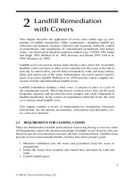
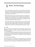
Because bare soil is vulnerable to soil erosion, establish temporary plant cover
soon after construction. A single severe storm falling on bare soil could remove
enough soil to require rebuilding the surface (Figure 11.1). Many native plants are
difcult to establish and they may grow slowly for up to 2 years; they need protection
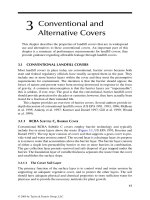
from competing weeds and effective soil erosion control during that time. Fortu-
nately, temporary plant cover or crop stubble can adequately control soil erosion for
2 years or longer (Figure 11.2).
© 2009 by Taylor & Francis Group, LLC
164 Evapotranspiration Covers for Landfills and Waste Sites
If the cover construction is completed during a nongrowing season, assess the
probability of soil erosion or deep percolation. Temporary erosion control may be
needed. Straw is an excellent temporary cover; however, even low-velocity winds can
remove it. Anchor straw mulch by crimping it into the soil, using chemical binders or
some other means. Other locally available temporary covers (e.g., wood chips, etc.)
may be acceptable.
If the cover construction is complete, during or just before an active growing season,
establish temporary vegetative cover immediately and irrigate if needed. An adequate,
temporary vegetative cover will control erosion, leave the cover soil in a relatively dry
condition, and control harmful soil crusts that may prevent grass establishment.
FIGURE 11.1 Soil erosion resulting from a single rain on a bare seedbed. (Photo courtesy
of USDA Natural Resources Conservation Service.)
FIGURE 11.2 Drill seeding in standing crop residue. (Photo courtesy of USDA Natural
Resources Conservation Service.)
© 2009 by Taylor & Francis Group, LLC
Construction 165
11.5 GRASS ESTABLISHMENT
Native grasses and forbs are difcult to establish in all climates, but especially so in
semiarid and arid climates. Seeding efforts to establish native grasses often fail. For
example, a 3 year study of native grass seeding in the humid areas of the Southern
Great Plains showed that 50% of farm and ranch seeding efforts failed (Great Plains
Council 1966).
The seeds of most native grasses and forbs are small; therefore, the maximum
seeding depth is shallow. Even in humid climates, the top 12 mm (1/2 in.) of bare
soil may dry below the plant wilting point in less than 1 day after a rain or irrigation.
The planting depth for most small seeds is between 3 and 6 mm (1/8 and 1/4 in.).
Small seeds planted deep, where the soil remains moist longer, produce few, if any,
plants because they have small food reserves. Small seeds exhaust their meager food
reserves before the seedling can produce leaves above ground. In addition, the best
available seed supply usually contains some immature seeds of poor quality; they
produce seedlings with low vigor that cannot survive deep planting.
11.5.1 SP e c I e S
In natural grassland ecosystems, most of the plant species will be grasses, but forbs
also form an important part of the plant community. Grasses are more widely planted
than are the associated forbs because grass seeds are easier to harvest than are forbs;
thus, they are more readily available. If seed supplies of locally adapted, desirable
forb species are available, they should be included in the mixture. However, forbs
may appear naturally in a planting of multiple grass species. At some locations, both
warm- and cool-season grasses are native; in such cases, plant both, but they may
need separate seeding dates.
11.5.2 fe r t I l I z e r
Fertilizer produces a benecial effect on cover establishment; however, do not apply
nitrogen fertilizer before establishing seeded permanent plants (Howard et al. 1977).
Nitrogen fertilizer applied before seeding the permanent species encourages exces-
sive growth of weeds during the grass establishment period. Phosphorus and potas-
sium applied before or during seeding may be less damaging than nitrogen. Excessive
weed growth seriously damages plant seedlings by competing for sunlight and soil
water. Apply nitrogen fertilizer, after the seeded species are established.
11.5.3 Se e d I n g ma c h I n e S
Many grass seeds have uffy seed coats that are difcult to remove; however, seed pro-
ducers have developed methods to improve many of these seeds. Many desirable plant
species have small seeds. Seeding machinery should be tight enough to hold the seed
and capable of planting uniform rates of uffy seeds over the entire land surface.
Some cool-season grasses and forbs may be planted up to 19 mm (3/4 in.) deep in
the standing stubble; but most warm-season grasses and forbs should be planted not
© 2009 by Taylor & Francis Group, LLC
166 Evapotranspiration Covers for Landfills and Waste Sites
more than 6 mm (1/4 in.) deep. Depth of seed placement is very important; furrow
openers using double disks with depth control bands or wheels on each furrow opener
best achieve the correct depth. Close the furrow with dual-angled press wheels or
an equivalent device to consolidate the soil around the seed. The seeder should have
adequate weight and down-pressure control to force the furrow openers into rm soil
and to ensure that each opener acts independently to accommodate uneven ground
surfaces. The seeding machine should travel at less than 4 km/h (2.5 mi/h) to ensure
correct planting and seed covering; higher speeds may result in uneven planting or
dropping of seeds on the soil surface.
11.5.4 Se e d I n g me t h o d S
Currently used methods for establishing native grasses and forbs include the following:
Hydroseeding•
Solid sod application and sprigging•
Broadcast seeding on the surface•
Drill seeding in bare soil•
Drill seeding in standing crop residue•
11.5.4.1 Hydroseeding
Hydroseeding was developed for steep slopes such as embankments along roadways
where conventional seeding machines cannot operate. It employs mixtures of seeds
and bers suspended in water. The seed and ber mix is pumped through nozzles at
high pressure to permit application up to 30 m away from the mobile seeding unit. The
bers used are commonly wood or straw; binders glue the bers together to reduce
movement by wind or rain after placement. Hydroseeding may deposit the seed within
the ber mulch, thus separating the seed from the soil and preventing plant establish-
ment. High winds may roll up the hydroseeded mats. Hydroseeding is expensive, and
in the western Great Plains, resulted in a 10% success rate on reclaimed minelands
(Dr. Gerald Schuman, personal communication, August 18, 1995).
11.5.4.2 Solid Sod Application and Sprigging
Solid sodding and sprigging successfully establish monocultures of sod-forming
grasses; however, both are expensive and need frequent irrigation during the estab-
lishment period. Other methods are more appropriate for establishment of grass on
landll covers where several species, including bunch grasses, are preferred rather
than a sod-grass monoculture.
11.5.4.3 Broadcast Seeding
Broadcasting seeds on the soil surface—either with or without mulch cover—
produces many seeding failures. Ants, mice, birds, and other creatures remove or
destroy large numbers of seeds. The germinating seeds dry rapidly in both humid
and arid conditions, producing high seedling mortality rates.
© 2009 by Taylor & Francis Group, LLC
Construction 167
11.5.4.4 Drill Seeding in Bare Soil
Seeds may be planted by drilling into furrows on bare soil. Erosion control during
plant establishment is a major problem, although mulch application after seeding
reduces erosion if enough mulch is applied. Rain on the bare soil may produce a
strong soil crust and other long-lasting unfavorable soil physical properties that limit
plant growth. Irrigation improves the success rate; however, this seeding method is
only moderately successful in arid and semiarid locations. It is more successful at
humid locations.
11.5.4.5 Drill Seeding Mulch Cover
A mulch of mature plant parts on the ground surface greatly improves the probabil-
ity for seeding success. Straw provides a good mulch cover. Even light winds move
loose straw; anchor it by crimping the straw into the soil with straight disks or with
materials that glue the bers together. Standing crop residue is excellent low-cost
mulch; it substantially improves the probability for seeding success. Drill seeding in
standing crop residue is both successful and economical (see Figure 11.2).
11.6 DRILL SEEDING IN STANDING CROP RESIDUE
11.6.1 b
e n e f I t S
Planting an annual grain crop such as barley, wheat, or oats quickly produces a thick
cover of standing stubble. The crop residue forms high-quality, durable mulch. These
annual grasses are easily established, and they produce a thick standing cover of
stubble. It is desirable to prevent the formation of viable grain in the plant heads to
avoid a second crop of grain. When the grain in the heads is forming, but still imma-
ture, and the stalks are mature, mow the crop at a height of about 0.2 m (8 in.) to
produce standing stubble or kill the crop with chemicals. The standing stubble will
control both wind and water erosion. Seed the desired perennial grasses and forbs
directly into the undisturbed standing stubble. The stubble cover reduces evaporation
of soil water from the seed zone, protects seedlings from temperature extremes, and
signicantly reduces weed competition.
Both eld research and production experience demonstrated that this method of
seeding is reliable and low in cost. With the addition of irrigation water during the
plant establishment phase, this method has a high probability for success.
11.6.2 mu l c h cr o P
Seed the mulch crop during the appropriate season. Examples of options for the
sites in Southern Great Plains with differing completion dates, include (1) in spring
or summer, seed Sudan grass; (2) in fall, seed winter wheat, rye, barley, or oats;
(3) in winter, seed spring barley, or oats. In the central and Northern Great Plains,
spring barley or wheat produces a durable and effective cover (Pinchak et al. 1985;
Schuman et al. 1980). The plants should be mowed 0.2 m (8 in.) high when imma-
ture seeds are in the milk stage (grain is lled with milky or soft material) of grain
© 2009 by Taylor & Francis Group, LLC
168 Evapotranspiration Covers for Landfills and Waste Sites
development to prevent reseeding the area with the crop. Seed the permanent vegeta-
tion into the standing stubble during the next appropriate planting season. Preserve
the standing stubble by minimizing machine operations on the land. The standing
stubble accomplishes the following:
1. Controls both wind and water erosion for up to 2 years
2. Shelters the seedlings from wind and the beating action of intense rainfall
3. Reduces the rate of soil drying
4. Maintains more uniform temperatures around seeds and seedlings than
bare soil
5. Increases inltration of precipitation or irrigation over that for bare soil
6. Costs one-fourth to one-twentieth as much as straw mulch applied to bare
soil
7. Suppresses undesirable weed growth
8. Improves soil physical properties to the 0.4-m depth (Schuman et al. 1980)
11.7 IRRIGATION
The cost of irrigation during cover establishment is a small fraction of the total cost
for landll completion; it greatly improves the probability for success with any seed-
ing method and at any location. Irrigation produces success in arid and semiarid
regions where failure is likely with rainfall alone. It is benecial at humid sites.
Sprinkler irrigation is the most practical method for irrigating a landll cover.
Sprinkler irrigation (1) can control the depth of soil wetted, thus protecting the waste
from drainage; (2) is adaptable to any cover shape or land slope; and (3) does not
require permanent structures on or near the cover. Water that is suitable for use on
irrigated crops is best for irrigating an ET cover. Irrigation requirements for eld
crops assume the use of water for many decades with consequent salt buildup in the
soil; this restriction does not apply to establishment of vegetation on an ET landll
cover. Because ET covers need irrigation for a short time, water of lesser quality may
be used. Treated sewage efuent and other water with moderate salt content may be
suitable for irrigating seedlings on ET covers.
11.8 NEW GRASS ESTABLISHMENT METHODS
Pregermination of grass seeds before planting was effective in experimental plant-
ings (Hauser 1986). It is effective and used commercially for vegetables; however,
grassland seeding with pregerminated seeds would require new equipment and
training of personnel.
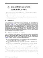
Water applied in the seed furrow is an inexpensive technique; it doubled the
number of seedlings established as compared to no water application in the seed
furrow [Figures 11.3 and 11.4; (Hauser 1989)]. The equipment needed is inexpensive
and readily available, and the user can attach it to any planter. In experimental plant-
ings, water applied in the seed furrow improved stand establishment in either moist
or dry conditions.
© 2009 by Taylor & Francis Group, LLC
Construction 169
11.9 CONSTRUCTION COMPLETION
The owner, appropriate governmental regulatory bodies, and other interested parties
will require certication that the cover meets the requirements for the site. Certi-
cation includes (1) construction QC reports, (2) construction records, and (3) certi-
cation that the records and reports are true and accurate. The guidance document
published by the ITRC provides specic requirements of the U.S. Environmental
Protection Agency (EPA) regarding certication (ITRC 2003).
REFERENCES
ASAE Standards, 50th ed. (2004a). Procedures for Obtaining and Reporting Data with the
Soil Cone Penetrometer, EP542. American Society of Agricultural and Biological
Engineers, St. Joseph, MI.
ASAE Standards, 50th ed. (2004b). Soil Cone Penetrometer, S313.3. American Society of
Agricultural and Biological Engineers, St. Joseph, MI.
Fulton, J. P. and Wells, L. G. (2005). Evaluation of a mechanical system for reconstructing
soil on surface mined land. Appl. Eng. Agric., 21(1): 43–51.
Water
Seed
Side View
Rear View
FIGURE 11.3 Double-disk furrow opener with water application in seed row. (Hauser 1989,
J. Soil and Water Conservation 44(2): 153–156. With permission.)
FIGURE 11.4 Grass growth 78 days after seeding. (Hauser 1989, J. Soil and Water Conser-
vation 44(2): 153–156. With permission.)
© 2009 by Taylor & Francis Group, LLC
170 Evapotranspiration Covers for Landfills and Waste Sites
Goldsmith, W., Silva, M., and Fischenich, C. (2001). Determining Optimal Degree of Soil
Compaction for Balancing Mechanical Stability and Plant Growth Capacity. ERDC
TN-EMRRP-SR-26, U.S. Army Engineer Research and Development Center, Vicks-
burg, MS. (accessed August 30, 2006).
Great Plains Council (1966). Stand Establishment Survey of Grass Plantings in the Great
Plains. Report No. 23. Great Plains Agricultural Council, Lincoln, NE.
Grossman, R. B. and Reinsch, T. G. (2002). Bulk density and linear extensibility. In Meth-
ods of Soil Analysis: Physical Methods, Part 4, Dane, J. H. and Topp, G. C. (Eds.),
pp. 201–228. Soil Science Society of America, Madison, WI.
Hauser, V. L. (1986). Emergence of several grasses from pregerminated seed and some soil
water effects. Agron. J., 78(1): 206–210.
Hauser, V. L. (1989). Improving grass seedling establishment. J. Soil and Water Conserva-
tion, 44(2): 153–156.
Hauser, V. L. and Chichester, F. W. (1989). Water relationships of claypan and constructed
soil proles. Soil Sci. Soc. Am. J., 53(4), 1189–1196.
Howard, G. S., Schuman, G. E., and Rauzi, F. (1977). Growth of selected plants on Wyoming
surface-mined soils and ash. J. of Range Management, 30(4): 306–310.
ITRC (2003). Technical and Regulatory Guidance for Design, Installation, and Monitoring
of Alternative Final Landll Covers. Interstate Technology and Regulatory Council,
444 Capitol St., NW, Suite 445, Washington, DC 2001. Also available at: http://www.
itrcweb.org/homepage.asp (accessed March 17, 2008).
Jones, C. A. (1983). Effect of soil texture on critical bulk densities for root growth. Soil Sci.
Soc. Am. J., 47:1208–1211.
Lowery, B. and Morrison, J. E., Jr. (2002). Soil penetrometers and penetrability. In Meth-
ods of Soil Analysis: Physical Methods, Part 4, Dane, J. H. and Topp, G. C. (Eds.),
pp. 363–388. Soil Science Society of America, Madison, WI.
McBride, R. A. (2002). Atterberg limits. In Methods of Soil Analysis: Physical Methods,
Part 4, Dane, J. H. and Topp, G. C. (Eds.), pp. 389–398. Soil Science Society of Amer-
ica, Madison, WI.
Pinchak, B. A., Schuman, G. E., and Depuit, E. J. (1985). Topsoil and mulch effects on plant
species and community responses of revegetated mined land. J. Range Management,
38(3):262–265.
Raper, R. L. and Kirby, J. M. (2006). Soil compaction: how to do it, undo it, or avoid doing it.
ASABE Distinguished Lecture Series No. 30, presented at the 2006 Agricultural Equip-
ment Technology Conference, Louisville, KY, 12–14 February 2006. American Society
of Agricultural and Biological Engineers, 2950 Niles Road, St. Joseph, MI, 49085.
Rhoades, J. D. and Loveday, J. (1990). Salinity in irrigated agriculture. In Irrigation of Agri-
cultural Crops. Stewart, B. A. and Nielsen, D. R. (Eds.). Agronomy No. 30. American
Society of Agronomy, Inc., Madison, WI.
Schuman, G. E., Taylor, E. M. Jr., Rauzi, F., and Howard, G. S. (1980). Standing stubble
versus crimped straw mulch for establishing grass on mined lands. J. Soil and Water
Conservation, 35(1): 25–27.
Sharpley, A. N. and Williams, J. R. (Eds). (1990). EPIC-Erosion/Productivity Impact Calcu-
lator: 1. Model Documentation. Technical Bulletin 1768. U.S. Department of Agricul-
ture, Washington, DC.
Sims, J. T. (1996). Lime requirement. In Methods of Soil Analysis: Chemical Methods, Part 3,
Co-editors: Sparks, Page, Helmke et al., pp. 491–515. Soil Science Society of America,
Madison, WI.
SSSA (1997). Glossary of Soil Science Terms. Soil Science Society of America, 677 South
Segoe Road, Madison, WI 53711.
© 2009 by Taylor & Francis Group, LLC
Construction 171
SSSA-3 (1996). Methods of Soil Analysis: Chemical Methods, Part 3. Co-editors: Sparks,
Page, Helmke, Loeppert, Soltanpour, Tabatabai, Johnson, and Sumner. Soil Science
Society of America (SSSA), 677 S. Segoe Rd., Madison, WI.
SSSA-4 (2002). Methods of Soil Analysis: Physical Methods, Part 4, Co-editors: J. H. Dane
and G. C. Topp. Soil Science Society of America (SSSA), 677 S. Segoe Rd., Madison,
WI.
USDA (1994). Soil Survey Staff. Keys to Soil Taxonomy, 6th edition, U.S. Government Print-
ing Ofce.
© 2009 by Taylor & Francis Group, LLC