báo cáo hóa học:" Can medio-lateral baseplate position and load sharing induce asymptomatic local bone resorption of the proximal tibia? A finite element study" pot
Bạn đang xem bản rút gọn của tài liệu. Xem và tải ngay bản đầy đủ của tài liệu tại đây (1.7 MB, 15 trang )
BioMed Central
Page 1 of 15
(page number not for citation purposes)
Journal of Orthopaedic Surgery and
Research
Open Access
Research article
Can medio-lateral baseplate position and load sharing induce
asymptomatic local bone resorption of the proximal tibia? A finite
element study
Bernardo Innocenti*
1
, Evelyn Truyens
2
, Luc Labey
1
, Pius Wong
1
, Jan Victor
3
and Johan Bellemans
2
Address:
1
European Centre for Knee Research, Smith & Nephew, Leuven, Belgium,
2
Department of Orthopaedic Surgery, Catholic University
Leuven, University Hospital Pellenberg, Pellenberg, Belgium and
3
AZ St-Lucas, Bruges, Belgium
Email: Bernardo Innocenti* - ; Evelyn Truyens - ;
Luc Labey - ; Pius Wong - ; Jan Victor - ;
Johan Bellemans -
* Corresponding author
Abstract
Background: Asymptomatic local bone resorption of the tibia under the baseplate can occasionally be
observed after total knee arthroplasty (TKA). Its occurrence is not well documented, and so far no
explanation is available. We report the incidence of this finding in our practice, and investigate whether it
can be attributed to specific mechanical factors.
Methods: The postoperative radiographs of 500 consecutive TKA patients were analyzed to determine
the occurrence of local medial bone resorption under the baseplate. Based on these cases, a 3D FE model
was developed. Cemented and cementless technique, seven positions of the baseplate and eleven load
sharing conditions were considered. The average VonMises stress was evaluated in the bone-baseplate
interface, and the medial and lateral periprosthetic region.
Results: Sixteen cases with local bone resorption were identified. In each, bone loss became apparent at
3 months post-op and did not increase after one year. None of these cases were symptomatic and
infection screening was negative for all. The FE analysis demonstrated an influence of baseplate positioning,
and also of load sharing, on stresses. The average stress in the medial periprosthetic region showed a non
linear decrease when the prosthetic baseplate was shifted laterally. Shifting the component medially
increased the stress on the medial periprosthetic region, but did not significantly unload the lateral side.
The presence of a cement layer decreases the stresses.
Conclusion: Local bone resorption of the proximal tibia can occur after TKA and might be attributed to
a stress shielding effect. This FE study shows that the medial periprosthetic region of the tibia is more
sensitive than the lateral region to mediolateral positioning of the baseplate. Medial cortical support of the
tibial baseplate is important for normal stress transfer to the underlying bone. The absence of medial
cortical support of the tibial baseplate may lead to local bone resorption at the proximal tibia, as a result
of the stress shielding effect. The presence of a complete layer of cement can reduce stress shielding,
though. Despite the fact that the local bone resorption is asymptomatic and non-progressive, surgeons
should be aware of this phenomenon in their interpretation of follow-up radiographs.
Published: 17 July 2009
Journal of Orthopaedic Surgery and Research 2009, 4:26 doi:10.1186/1749-799X-4-26
Received: 14 January 2009
Accepted: 17 July 2009
This article is available from: />© 2009 Innocenti et al; licensee BioMed Central Ltd.
This is an Open Access article distributed under the terms of the Creative Commons Attribution License ( />),
which permits unrestricted use, distribution, and reproduction in any medium, provided the original work is properly cited.
Journal of Orthopaedic Surgery and Research 2009, 4:26 />Page 2 of 15
(page number not for citation purposes)
Background
One of the major failure mechanisms in total knee arthro-
plasty (TKA) is aseptic loosening of the tibial component.
In the past this has been attributed to the quality of the fix-
ation as well as to the strength of the supporting bone,
which is subject to a more or less pronounced stress
shielding effect of the proximal tibial metaphyseal bone
by the tibial baseplate [1-7].
Asymptomatic local bone resorption of the proximal tibia
under the prosthetic component can occasionally be
observed after TKA (Figure 1). Its occurrence is not well
documented in the literature and we are not aware of any
publication that provides a clear explanation for this phe-
nomenon. Its observation during postoperative follow-up
is usually concerning to the surgeon since its significance
is not well understood. In literature two main reasons for
bone resorption can be found:
- Wear particles, which can induce focal osteolysis [8-
13];
- Non-physiological loading conditions, mainly due
to malalignment and malpositioning of the prosthesis
[1-3,14-18]. In our cases the first hypothesis can be
rejected because the observed bone resorption became
apparent as soon as three months post operatively
[11,19-21].
In this study we report the incidence of this 'short term'
local bone resorption, and we investigate whether it can
be attributed to a stress shielding effect, which might lead
to more generalized bone resorption in the long term and
potential aseptic loosening.
The overall stress distribution in a prosthetized tibia has
been examined using FEA in the past already. Several
parameters that can influence the stress distribution like
design, material properties and fixation technique of TKA
implants have been investigated. The loading conditions
at the tibio-femoral interface and the implant position,
may also affect the stress distribution (particularly
locally), but these parameters have not been thoroughly
examined [1,5-7]. For this reason, this study analyzes the
possible local effects of mediolateral load distribution
and implant positioning on the mechanical stress in sev-
eral regions of a prosthetized tibia.
Methods
The postoperative radiographs, made at 3 months and 1
year follow-up, of 500 consecutive TKA patients per-
formed at our institution were analyzed to determine the
incidence of local bone resorption under the tibial base-
plate. All the analyzed radiographs were made under
fluoroscopic guidance to ascertain true horizontal align-
ment of the baseplate.
All the surgical procedures were performed by the same
surgeon using and the same surgical approach. All cases
had undergone a standard posterior stabilized TKA using
cemented fixation of either the Genesis II or Profix System
(Smith & Nephew, Memphis, TN). Sixteen cases that were
identified were further analyzed and underwent screening
for infection including determination of sedimentation
rate and C-reactive protein (CRP) levels, as well as joint
aspiration and culture. Figure 1 shows a typical case of a
patient in whom such a local bone resorption was found.
Based on the identified cases, a three-dimensional finite
element model of the tibia with the prosthesis in situ was
developed (Abaqus/Standard version 6.6-1, Abaqus, Inc.,
Providence, RI) from the "Standard Tibia" model [1,5,22-
26]. This model was adapted for the implantation of a
standard Genesis II asymmetric tibial Ti baseplate and its
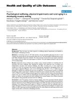
Patient with asymptomatic focal osteolysis of the proximal tibiaFigure 1
Patient with asymptomatic focal osteolysis of the
proximal tibia. (a) Radiographs demonstrating well fixed
components and normal bone-implant interface 3 months
after surgery. (b) asymptomatic focal osteolysis of the proxi-
mal tibia under the prosthetic component at 1 year followup.
Journal of Orthopaedic Surgery and Research 2009, 4:26 />Page 3 of 15
(page number not for citation purposes)
UHMWPE insert. A size 5 baseplate was chosen for this
study since it is a common size used in clinical practice.
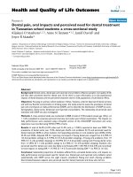
The tibial bone model was scaled such that the resected
proximal bone surface would be 3.0 mm larger in the
mediolateral (ML) direction than the baseplate (Figure 2).
Three regions of interest (ROI) in the tibia model were
defined: the bone-baseplate interfacial ROI, the medial
periprosthetic ROI, and the lateral periprosthetic ROI
(Figures 2, 3). Based on the 16 patients' radiographs, the
dimensions of each periprosthetic ROI were chosen to be
10 mm wide mediolaterally and 5 mm high. Each ROI
had an anteroposterior length that spanned the bone (Fig-
ures 2, 3).
The baseplate was implanted on the tibia, following the
surgical technique at an 11 mm tibial resection level per-
pendicular to the intramedullary canal [27]. The baseplate
was placed initially in a central mediolateral position,
equidistant from the medial and lateral edges of the bone
(Figure 2). To simulate the presence or not of the cement
between the tibial insert and the bone, two different mod-
els were defined. In the cementless model an interface gap
of 1 mm was left between the cancellous bone and the
stem/fin construct. When the implant was shifted to the
medial or to the lateral side, this interface gap around the
stem/fin construct was repositioned accordingly. Figures
2, 3 show example tibial constructs. To consider the effect
of the cement, a layer of bone cement of 4 mm was con-
sidered between the bone and the baseplate and no gap
was considered between the two structures [28,29].
Although cortical and cancellous bone show viscoelastic
properties, the assumption of linear elasticity is adequate
for most studies [1,5,24,30-34]. Accordingly, in this study,
bone was assumed to be linearly elastic and isotropic. The
material properties and behavior of the cortical bone, can-
cellous bone and titanium alloy are shown in Table
1[1,34,35]. The UHMWPE was assumed to be a non-lin-
ear elastic-plastic material according to the literature (E =
685 MPa, υ = 0.4, [36-41]). Also the cement layer was
Central position of the prosthesis in the tibia model; the baseplate is equidistant from the medial and lateral edges of the boneFigure 2
Central position of the prosthesis in the tibia model; the baseplate is equidistant from the medial and lateral
edges of the bone. The medial and lateral regions of interest are dimensioned and colored. The picture shows only the prox-
imal bone for clarity.
Journal of Orthopaedic Surgery and Research 2009, 4:26 />Page 4 of 15
(page number not for citation purposes)
assumed to have linear elastic material properties (E = 3.0
GPa, υ = 0.3, [42-46]).
Based on literature a coefficients of friction of 0.15 was
chosen for the insert-baseplate interface, a coefficient of
friction of 0.2 was chosen for the bone-baseplate interface
and a coefficients of friction of 0.3 was chosen for the
cement-baseplate and cement-bone interface [42-46].
A static load of 800 N, corresponding to average body
weight, was applied on two contact areas placed on the
lateral and the medial condyles. The load was shared
between the two areas in eleven load distributions, rang-
ing from 0 to 100% (100 to 0%) on the lateral (medial)
condyle with steps of 10%. The load on each area was dis-
tributed homogenously and perpendicularly to the base-
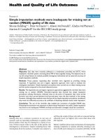
plate for each load sharing configuration. To identify the
magnitude of the loading contact areas on the polyethyl-
ene, a static experimental test was performed on a same
size Genesis II femoral component against a size 5–6 tib-
ial insert using a dye method and a loading frame. Based
on this study, ellipsoidal contact areas on the medial and
lateral condyles were created on the insert with magni-
tudes of 121 mm
2
and 132 mm
2
, respectively in the same
position as seen in the experimental study. Figure 4 shows
the result of the experiment and also the location and the
magnitude of the contact area used for the numerical
model.
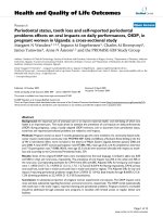
Mesh of the three-dimensional Finite Element model of the prosthetized tibiaFigure 3
Mesh of the three-dimensional Finite Element model of the prosthetized tibia. a) Complete FE model mesh; b)
Proximal view demonstrating the higher density of the mesh at the three ROI's, which are shown in different colors.
Table 1: Material properties and material behaviour used in this study [1,30].
Material Young's Modulus E (GPa) Poisson's ratio Material behavior
Cortical Bone 16.6 0.3 Homogeneous, linearly elastic, isotropic
Cancellous Bone 2.4 0.3 Homogeneous, linearly elastic, isotropic
Titanium Alloy (Ti6Al4V) 117 0.3 Homogeneous, linearly elastic, isotropic
Journal of Orthopaedic Surgery and Research 2009, 4:26 />Page 5 of 15
(page number not for citation purposes)
For each load sharing configuration, seven baseplate posi-
tions were simulated:
1. the central ML position (Figure 2);
2. 0.5 mm medial displacement from the central position;
3. 1 mm medial displacement from the central position;
4. 1.5 mm medial displacement from the central position
(the medial edge of the prosthesis component is in con-
tact with the medial edge of the bone);
5. 0.5 mm lateral displacement from the central position;
6. 1 mm lateral displacement from the central position;
7. 1.5 mm lateral displacement from the central position
(the lateral edge of the prosthesis component is in contact
with the lateral edge of the bone).
The tibial bone model was trimmed distally and the cut
section was considered fixed in all the simulations (Figure
3). The entire model was meshed with approximately
55,000 modified 8-node tetrahedral elements; the mesh
density was increased for the three ROIs (Figure 3). Con-
vergence of the FEA was checked using several mesh den-
sities ranging from 5,000 up to 90,000 elements for two
different configurations (central ML and 1 mm lateral
position of the baseplate both with 50% load on each
condyle).
One hundred-fifty-four simulations were run in total (11
load sharing conditions – 7 positions – cementless and
cemented techniques). For each simulation, the average
VonMises stress in each ROI was evaluated and plotted
versus lateral load share and implant position.
Result
Clinical and radiographic observation
Of the 500 patients analyzed, only 16 cases (3.2%)
showed local bone resorption of the proximal tibia.
Resorption was seen on the medial side only. In each of
these, the bone loss became apparent on radiographs at 3
months follow-up (Figure 1) and did not increase after
one year. None of these cases were clinically symptomatic,
and all 16 patients had "good" to "excellent" knee pain
and function scores. Infection screening including joint
aspiration was negative for all. Postoperative full leg radi-
ographs demonstrated an overall mechanical alignment
of neutral ± 3 degrees for all cases. Analysis of the pre-,
per- and postoperative parameters of these 16 cases did
not show any significant difference in either in parameters
related to the preoperative status or diagnosis, the opera-
tive technique, implant specifications, or postoperative
radiographic data when compared to the average of our
database. No obvious difference between knee alignment
and overall morphology of the knees in this 16 patients
compare top the overall population. The only consistent
finding in retrospect on these 16 cases was the absence of
tibial cortical rim contact on the medial side, due to either
an undersized tibial baseplate or a somewhat lateralized
position of the baseplate.
Contact area's as found experimentally (on the left side), and contact areas used in the numerical model (on the right)Figure 4
Contact area's as found experimentally (on the left side), and contact areas used in the numerical model (on
the right).
Journal of Orthopaedic Surgery and Research 2009, 4:26 />Page 6 of 15
(page number not for citation purposes)
FEA Results
Convergence
The results of the convergence test are shown in figure 5.
The average Von Mises stress for the lateral and medial
ROIs is constant for all meshes above 30,000 elements.
Interface ROI
The results of the finite element analysis demonstrated
that stress in the interfacial ROI was lowest when load
sharing was equal between medial and lateral. (Figure 6a)
The average stress in the interfacial ROI was not influ-
enced by mediolateral baseplate position. (Figure 6b)
Lateral ROI
Stress in the lateral ROI increased significantly when the
load was predominantly lateral, and decreased when the
load was progressively shared with the medial side. (Fig-
ure 7a) This finding was dependent on implant position,
with a greater decrease in stress on the lateral ROI when
the tibial component was shifted medial.
Shifting the baseplate medial away from the lateral cortex
caused reduced stress on the lateral ROI, especially in con-
ditions of important load sharing towards the medial side
(Figure 7b).
Medial ROI
Stress in the medial ROI increased significantly when the
load was predominantly medial, and decreased when the
load was progressively shared with the lateral side. (Figure
8a) This finding was again dependent on implant posi-
tion, with a greater decrease in stress on the medial ROI
when the tibial component was shifted lateral.
Shifting the baseplate lateral away from the medial cortex
caused reduced stress on the medial ROI, especially in
conditions of important load sharing towards the lateral
side (Figure 8b).
Effect of cement layer
The use of a cement layer between the tibial component
and the bone induced a general reduction of the stress in
all the ROIs. The overall trends described above remain
Average VonMises stress in the Lateral ROI and in the Medial ROI for different number of elements in two configurationsFigure 5
Average VonMises stress in the Lateral ROI and in the Medial ROI for different number of elements in two
configurations. a) central ML baseplate position, 50% load on each condyle; b) 1 mm lateral displacement of the baseplate
from the central position, 50% load on each condyle.
Journal of Orthopaedic Surgery and Research 2009, 4:26 />Page 7 of 15
(page number not for citation purposes)
Average VonMises stresses in the interfacial ROI plotted versus load share (a) and baseplate position (b)Figure 6
Average VonMises stresses in the interfacial ROI plotted versus load share (a) and baseplate position (b). A 0%
lateral share means that the entire load was applied on the medial area. A negative baseplate positioning means a shift of the
component towards the lateral side.
Journal of Orthopaedic Surgery and Research 2009, 4:26 />Page 8 of 15
(page number not for citation purposes)
Average VonMises stresses in the lateral ROI plotted versus load share (a) and positioning (b)Figure 7
Average VonMises stresses in the lateral ROI plotted versus load share (a) and positioning (b). A 0% lateral share
means that the entire load was applied on the medial area. A negative baseplate positioning means a shift of the component
towards the lateral side.
Journal of Orthopaedic Surgery and Research 2009, 4:26 />Page 9 of 15
(page number not for citation purposes)
Average VonMises stresses in the medial ROI plotted versus load share (a) and positioning (b)Figure 8
Average VonMises stresses in the medial ROI plotted versus load share (a) and positioning (b). A 0% lateral share
means that the entire load was applied on the medial area. A negative baseplate positioning means a shift of the component
towards the lateral side.
Journal of Orthopaedic Surgery and Research 2009, 4:26 />Page 10 of 15
(page number not for citation purposes)
valid. Figure 9 shows an example of the average VonMises
stress in the medial ROI for cemented and cementless
techniques under the same load condition.
ROI comparison
If we compare the variation of the average VonMises stress
in the lateral ROI as a function of load sharing (Figure 7a)
we see that the maximum variation is about 0.76 MPa
(max = 1.22 MPa, min = 0.46 MPa). Similarly if we com-
pare the variation of the average VonMises stress in the
medial ROI as a function of load sharing (Figure 7a) we
see that the maximum variation is about 0.75 MPa (max
= 1.08 MPa, min = 0.33 MPa).
If we compare the variation of the average VonMises stress
in the lateral ROI as a function of position (Figure 7b) we
see that the maximum variation is about 0.26 MPa (max
= 0.71 MPa, min = 0.45 MPa). In contrast, if we compare
the variation of the average VonMises stress in the medial
ROI as a function of position (Figure 8b) we see that the
maximum variation is about 0.37 MPa (max = 0.70 MPa,
min = 0.33 MPa). Although this variation doesn't seem
very high in absolute values, the relative variation in the
medial and the lateral ROI is considerably different.
Discussion
In this paper we present radiographic evidence of short
term local bone resorption. This phenomenon is clinically
asymptomatic and occurs in about 3% of the patients. It
cannot be attributed to infection or wear and therefore we
investigated possible mechanical reasons such as medio-
lateral load distribution and baseplate position. A finite
Effect on the Average VonMises stress due to cement techniqueFigure 9
Effect on the Average VonMises stress due to cement technique. In this picture is shown the Average Stress in the
medial ROI for 100% of load sharing for cemented and cementless technique.
Journal of Orthopaedic Surgery and Research 2009, 4:26 />Page 11 of 15
(page number not for citation purposes)
element analysis of a tibia implanted with a tibial knee
arthroplasty baseplate was performed to investigate the
stress distribution in the proximal tibial metaphysis.
Three regions of interest were evaluated: the total interface
between bone and tibial component (interfacial ROI), the
medial periprosthetic region, as well as the lateral
periprosthetic region of the proximal tibial metaphysis.
Cemented and cementless techniques were considered.
Our results demonstrate that in the interfacial ROI the
average stress was not sensitive to implant position, but
was moderately sensitive to load sharing (Figure 6a).
Higher average stress values were obtained when the load
was exclusively applied on one condyle, and lower values
were observed when the load was shared more evenly
amongst both compartments. This finding is logical, since
application of the load on only one condyle generates a
moment that disappears when the load is evenly distrib-
uted between both condyles. Figure 10 clearly demon-
strates this phenomenon: when load is applied exclusively
medially or laterally (Figure 10 left row and right row) the
stress concentrates near respectively the lateral and the
medial edge of the stem/fin construct, whereas an equally
distributed load amongst both condyles (Figure 10 mid-
dle row) will generate no moment and therefore also
lower the stress on the edges.
The average stress in the lateral ROI as a function of load
sharing (Figure 7a and Figure 11) is almost constant as
long as the lateral condyle carries less than 50% of the
load. When the lateral condyle carries more than 50% of
the load, the stress in the lateral ROI increases linearly.
Stress in the lateral ROI presented a linear relationship
with implant position (Figure 7b and Figure 11) for all of
the considered load distributions. However, the slope of
this linear relationship is not constant. It is steeper as soon
VonMises stress distribution on the interface area for different positions (a) and load sharing (b) conditionsFigure 10
VonMises stress distribution on the interface area for different positions (a) and load sharing (b) conditions.
Journal of Orthopaedic Surgery and Research 2009, 4:26 />Page 12 of 15
(page number not for citation purposes)
as less than 50% of the load is carried by the lateral con-
dyle.
The average stress in the medial ROI as a function of load
sharing (Figure 8a and Figure 12) behaves almost identi-
cal as in the lateral ROI. It is almost constant as long as the
medial condyle carries less than 50% of the load, when
the condyle carries more the stress increases linearly.
In contrast, the average stress in the medial ROI as a func-
tion of implant position (Figure 8 and Figure 12), presents
different behaviour compared to the stress in the lateral
ROI.
The average stress in the medial ROI changes non linearly
when the component is placed near the medial edge of the
cortex and the medial condyle carries less than 50% of the
load. This change becomes linear as soon as the compo-
nent is shifted more than 1 mm away from maximal
medial cover (Figure 8b).
This change is also much less dramatic when load is
greater than 50% on the medial compartment, such as
one could expect in case of a varus alignment. This again
is a logical finding. Medial compartment load is high in
the varus situation, and shifting away the tibial compo-
nent lateral from the medial cortex will not lead to an
important reduction of stress on the medial side. In the
valgus situation however, load on the medial compart-
ment is already reduced, and shifting the component
away from medial cortex will further reduce the medial
tibial stress in an important way.
Simulation of cemented fixation of the baseplate shows
similar trends as in a cementless fixation.
VonMises stress distribution on the Lateral ROI for different position (a) and load sharing (b) conditionsFigure 11
VonMises stress distribution on the Lateral ROI for different position (a) and load sharing (b) conditions.
Journal of Orthopaedic Surgery and Research 2009, 4:26 />Page 13 of 15
(page number not for citation purposes)
FEA results indicate that the tibial positioning is more
important than the load distribution on the VonMises
stress in the medial tibial ROI. This is in agreement with
the full leg radiographs that show proper alignment, and
thus normal load sharing, in the 16 cases where local
bone resorption occurs.
Based upon our findings the average stress in the medial
ROI seems therefore more sensitive than the lateral ROI to
implant position and to a certain extent also to load shar-
ing.
If we compare the decrease of the average stress in the
medial and lateral ROI for 1 mm shift of the component
away from the respective cortex in the range of the physi-
ological load sharing condition (60% of the load on the
medial condyle), we obtain a decrease on the medial ROI
which is more than 50% greater than the decrease in the
lateral ROI (stress in medial ROI changes 0.19 MPa/mm,
stress in lateral ROI changes 0.12 MPa/mm, Figure 7b, Fig-
ure 8b). Although the variation of the average VonMises
stress in the lateral and the medial ROI doesn't seem very
high in absolute values (0.26 MPa and 0.37 MPa respec-
tively), the relative variation in the lateral and the medial
ROI is very different (45% and 72% respectively).
We believe that our finite element data shows that impor-
tant stress relief can easily occur on the medial side when
the tibial implant is not positioned on the medial cortex,
and that this could lead to unloading the medial cortex.
Our finite element data also shows that the lateral cortex
is much less subject to stress deprivation in case the tibial
component is not or less in contact with the lateral cortex.
The reason for this may be the fact that the lateral tibial
cortex is much less pronounced and solid compared to the
medial cortex, and therefore may much less contribute to
VonMises stress distribution on the Medial ROI for different position (a) and load sharing (b) conditionsFigure 12
VonMises stress distribution on the Medial ROI for different position (a) and load sharing (b) conditions.
Journal of Orthopaedic Surgery and Research 2009, 4:26 />Page 14 of 15
(page number not for citation purposes)
stress transfer. Although our FEA is not sufficient to
explain completely the local asymptomatic bone resorp-
tion phenomena that we found in our clinical observa-
tions; these results may contribute to an explanation and
certainly warrants further investigations. Even if the leg
alignment in the 16 patients was normal, or at least not
abnormal, only more detailed in vivo analysis can evalu-
ate the exact load sharing condition in these knees to
allow the confirmation of our finite element analysis. Also
the influence of other parameters (i.e. thickness of tibial
baseplate, symmetric geometry of the tibial tray) and the
effect of other positioning factors (slope, varus-valgus and
rotation) will be further examined.
Competing interests
Bernardo Innocenti, Luc Labey and Pius Wong are all
employees of the Smith & Nephew Company. They are all
working at the European Centre for Knee Research
(Smith&Nephew) in Leuven, Belgium.
Jan Victor and Johan Bellemans are both consultant for
the Smith & Nephew Company and supervised studies in
the European Centre for Knee Research, Leuven, Belgiun.
Authors' contributions
All the authors participated in the design of the study. ET,
JB carried out the radiographic analysis. BI, PW carried out
the Finite element analysis. All the authors helped to draft
the manuscript. All authors read and approved the final
manuscript.
References
1. Au AG, Raso VJ, Liggins AB, Amirfazli A: Contribution of loading
conditions and material properties to stress shielding near
the tibial component of total knee replacements. J Biomech
2007, 40:1410-1416.
2. Soininvaara TA, Miettinen HJ, Jurvelin JS, Suomalainen OT, Alhava EM,
Kroger HP: Periprosthetic tibial bone mineral density changes
after total knee arthroplasty: one-year follow-up study of 69
patients. Acta Orthop Scand 2004, 75:600-605.
3. Van Loon CJM, De Waal Malefijt MC, Buma P, Verdonschot N, Veth
RPH: Femoral bone loss in total knee arthroplasty: a review.
Acta Orthop Belg 1999, 65:154-163.
4. Bureau MN: Biomimetic polymer composites for orthopedic
implants. Proceedings of the Third International Symposium on
Advanced Biomaterials and Biomechanics, Montreal 2005:142.
5. Au AG, Liggins AB, Raso VJ, Amirfazli A: A parametric analysis of
fixation post shape in tibial knee prostheses. Med Eng Phys
2005, 27:123-134.
6. Askew MJ, Lewis JL: Analysis of model variables and fixation
post length effects on stresses around a prosthesis in the
proximal tibia. J Biomech Eng 1981, 103:239-245.
7. Au AG: Development of a computational finite element tool
for the stress analysis of the femur and tibia. In M.Sc Thesis Uni-
versity of Alberta, Department of Mechanical Engineering and
Department of Biomedical Engineering; 2003.
8. Peters PC, Engh GA, Dwyer KA, Vinh TN: Osteolysis after total
knee arthroplasty without cement. J Bone Joint Surg Am 1992,
74:864-876.
9. Gross TP, Lennox DW: Osteolytic cyst-like area associated
with polyethylene and metallic debris after total knee
replacement with an uncemented vitallium prosthesis: a
case report. Bone Joint Surg Am 1992, 74:1096-1101.
10. Robinson EJ, Mulliken BD, Bourne RB, Rorabeck CH, Alvarez C: Cat-
astrophic osteolysis in total knee replacement: a report of 17
cases. Clin Orthop 1995, 321:
98-105.
11. Berry DJ, Wold LE, Rand JA: Extensive osteolysis around an
aseptic, stable, uncemented total knee replacement. Clin
Orthop Relat Res 1993, 293:204-207.
12. Kane KR, Deheer DH, Beebe JD, Bereza R: An osteolytic lesion
associated with polyethylene debris adjacent to a stable total
knee prosthesis. Orthop Rev 1994, 23:332-337.
13. Kilgus DJ, Funahashi TT, Campbell PA: Massive femoral osteolysis
and early disintegration of a polyethylene-bearing surface of
a total knee replacement. J Bone Joint Surg Am 1992, 74:770-774.
14. Watanabe T, Tomita T, Fujii M, Kaneno M, Sakaura H, Takeuchi E,
Sugamoto K, Yoshikawa H: Periprosthetic fracture of the tibia
associated with osteolysis caused by failure of rotating
patella in low-contact-stress total knee arthroplasty. J Arthro-
plasty. 2002, 17(8):1058-1062.
15. Felix NA, Stuart MJ, Hanssen AD: Periprosthetic fractures of the
tibia associated with total knee arthroplasty. Clin Orthop 1997,
345:113-124.
16. Deniss DA: Periprosthetic fracture following total knee
arthroplasty. J Bone Joint Surg Am 2001, 83:120-130.
17. Rand JA, Coventry MB: Stress fracture after total knee arthro-
plasty. J Bone Joint Surg Am 1980, 62:226-233.
18. Completo A, Fonseca F, Simoes JA: Strain shielding in proximal
tibia of stemmed knee prosthesis: experimental study. J Bio-
mech 2008, 41:560-566.
19. Huang CH, Ma HM, Liau JJ, Ho FY, Cheng CK: Osteolysis in failed
total knee arthroplasty: A comparison of mobile-bearing and
fixed-bearing knees. J Bone Joint Surg Am 2002, 84:2224-2229.
20. O'Rourke MR, Callaghan JJ, Goetz DD, Sullivan PM, Johnston RC:
Osteolysis associated with a cemented modular posterior-
cruciate-substituting total knee design: Five to eight-year
follow-up. J Bone Joint Surg Am
2002, 84:1362-1371.
21. Naudie DDR, Ammeen DJ, Engh GA, Rorabeck CH: Wear and
osteolysis around total knee arthroplasty. J Am Acad Orthop
Surg 2007, 15:53-64.
22. "the Standardize Tibia": 2008 [med-
town.orbiomed_town/LHDL/Reception/datarepository/repositories/
BelRep WikiPages/StandardisedTibiaPolygonalSurface].
23. Gray H, Gill R: University of Oxford. From: The BEL Reposi-
tory. 2008 [ />].
24. Au AG, Raso VJ, Liggins AB, Otto DD, Amirfazli A: A three-dimen-
sional finite element analysis for tunnel placement and but-
tons in anterior cruciate ligament reconstructions. J Biomech
2005, 38:827-832.
25. Greer BB: Finite element modeling an danalysis of the proxi-
mal femur. In M.Sc Thesis University of Nevada; Department of
Mechanical Engineering; 1999.
26. Heiner AD, Brown TD: Structural properties of a new design of
composite replicate femurs and tibias. J Biomech 2001,
34:773-781.
27. Genesis II Total Knee System: System Specifications Smith & Nephew Sur-
gical Technique 7128-0429; 1997.
28. Peters CL, Craig MA, Mohr RA, Bachus KN: Tibial component fix-
ation with cement. Full versus surface cementation tech-
niques. Clin Orthop Relat Res 2003, 409:158-168.
29. Lutz MJ, Pincus PF, Whitehouse SL, Halliday BR: The effect of
cement gun and cement syringe use on the tibial cement
mantle in total knee arthroplasty. J Arthroplasty. 2009,
24(3):461-467.
30. Sarathi Kopparti P, Lewis G: Influence of three variables on the
stresses in a three-dimensional model of a proximal tibia-
total knee implant construct. Biomed Mater Eng. 2007,
17(1):19-28.
31. Ashman RB, Van Buskirk WC: The elastic properties of a human
mandible. Adv Dent Res 1987, 1:64-67.
32. Rho JY: An ultrasonic method for measuring the elastic prop-
erties of human tibial cortical and cancellous bone. Ultrasonics
1996, 34:777-783.
33. Cowin SC: Bone Mechanics 2nd edition. Boca Raton, FL: CRC Press;
2001.
34. Sawatari T, Tsumura H, Iesaka K, Furushiro Y, Torisu T: Three-
dimensional finite element analysis of unicompartmental
knee arthroplasty – the influence of tibial component inclina-
tion. J Orthop Res. 2005, 23(3):549-554.
Publish with BioMed Central and every
scientist can read your work free of charge
"BioMed Central will be the most significant development for
disseminating the results of biomedical research in our lifetime."
Sir Paul Nurse, Cancer Research UK
Your research papers will be:
available free of charge to the entire biomedical community
peer reviewed and published immediately upon acceptance
cited in PubMed and archived on PubMed Central
yours — you keep the copyright
Submit your manuscript here:
/>BioMedcentral
Journal of Orthopaedic Surgery and Research 2009, 4:26 />Page 15 of 15
(page number not for citation purposes)
35. Senepati SK, Pal S: UHMWPE-alumina ceramic composite, an
improved prosthesis material for an artificial cemented hip
joint. Trends Biomater Artif Organs 2002, 16:5-7.
36. Halloran JP, Petrella AJ, Rullkoetter PJ: Explicit finite element
modelling of total knee replacement mechanics. J Biomech
2005, 38:323-331.
37. Bartel DL, Rawlinson JJ, Burstein AH, Ranawat CS, Flynn WF:
Stresses in polyethylene components of contemporary total
knee replacements. Clin Orthop 1995, 317:76-82.
38. Godest AC, Beaugonin M, Haug E, Taylor M, Gregson PJ: Simulation
of a knee joint replacement during a gait cycle using explicit
finite element analysis. J Biomech 2002, 35:267-275.
39. Prutt LA: Conventional and cross-linked polyethylene proper-
ties. In Total knee arthroplasty – a guide to get better performance
Edited by: Bellemans L, Ries MD, Victor J. Heidelberg, Germany:
Springer Verlag; 2005:353-360.
40. Soncini M, Vandini L, Redaelli A: Finite element analysis of a knee
joint replacement during a gait cycle. J Appl Biomater Biomech
2004, 2:45-54.
41. DeHeer DC, Hillberry BM: The effect of thickness and non-lin-
ear material behavior on contact stresses in polyethylene
tibial components. Trans 38th Annual Meeting, Orthopaedic Research
Society 1992.
42. Janssen D, Mann KA, Verdonscot N: Micro-mechanical modeling
of the cement-bone interface: the effect of friction, morphol-
ogy and material properties on the micromechanical
response. J Biomech 2008, 41:3158-3163.
43. Rancourt D, Shirazi-Adl A, Drouin G, Paiement G: Friction proper-
ties of the interface between porous-surfaced metals and tib-
ial cancellous bone. J Biomed Mater Res 1990, 24:1503-1519.
44. Simon A, Augat P, Ignatius A, Claes L: Influence of the stiffness of
bone defect implants on the mechanical conditions at the
interface – a finite element analysis with contact. J Biomech
2003, 36:1079-1086.
45. Tissakht M, Eskandari H, Ahmed AM: Micromotion analysis of the
fixation of total knee tibial component. Comput Struct 1995,
36:365-375.
46. Janssen D, Mann KA, Verdonschot N: Finite element simulation
of cement-bone interface micromechanics: a comparison to
experimental results. J Orthop Res 2009, 1:1-7.