báo cáo hóa học:" A biomechanical assessment of modular and monoblock revision hip implants using FE analysis and strain gage measurements" potx
Bạn đang xem bản rút gọn của tài liệu. Xem và tải ngay bản đầy đủ của tài liệu tại đây (1.49 MB, 12 trang )
Bougherara et al. Journal of Orthopaedic Surgery and Research 2010, 5:34
/>Open Access
TECHNICAL NOTE
BioMed Central
© 2010 Bougherara et al; licensee BioMed Central Ltd. This is an Open Access article distributed under the terms of the Creative Com-
mons Attribution License ( which permits unrestricted use, distribution, and reproduc-
tion in any medium, provided the original work is properly cited.
Technical Note
A biomechanical assessment of modular and
monoblock revision hip implants using FE analysis
and strain gage measurements
Habiba Bougherara
1
, Rad Zdero*
1,2
, Suraj Shah
2
, Milan Miric
1
, Marcello Papini
1
, Paul Zalzal
3
and Emil H Schemitsch
2,4
Abstract
Background: The bone loss associated with revision surgery or pathology has been the impetus for developing
modular revision total hip prostheses. Few studies have assessed these modular implants quantitatively from a
mechanical standpoint.
Methods: Three-dimensional finite element (FE) models were developed to mimic a hip implant alone (Construct A)
and a hip implant-femur configuration (Construct B). Bonded contact was assumed for all interfaces to simulate long-
term bony ongrowth and stability. The hip implants modeled were a Modular stem having two interlocking parts
(Zimmer Modular Revision Hip System, Zimmer, Warsaw, IN, USA) and a Monoblock stem made from a single piece of
material (Stryker Restoration HA Hip System, Stryker, Mahwah, NJ, USA). Axial loads of 700 and 2000 N were applied to
Construct A and 2000 N to Construct B models. Stiffness, strain, and stress were computed. Mechanical tests using axial
loads were used for Construct A to validate the FE model. Strain gages were placed along the medial and lateral side of
the hip implants at 8 locations to measure axial strain distribution.
Results: There was approximately a 3% average difference between FE and experimental strains for Construct A at all
locations for the Modular implant and in the proximal region for the Monoblock implant. FE results for Construct B
showed that both implants carried the majority (Modular, 76%; Monoblock, 66%) of the 2000 N load relative to the
femur. FE analysis and experiments demonstrated that the Modular implant was 3 to 4.5 times mechanically stiffer than
the Monoblock due primarily to geometric differences.
Conclusions: This study provides mechanical characteristics of revision hip implants at sub-clinical axial loads as an
initial predictor of potential failure.
Background
About 150,000 total hip arthroplasty (THA) surgeries are
performed each year in the United States [1]. This is the
most common surgical treatment for hip osteoarthritis
and rheumatoid arthritis, which may begin as a complex
mechano-chemical degenerative cascade [2]. Subsequent
revision hip arthroplasty may be necessitated by compo-
nent dislocation, protrusion, malalignment, wear, frac-
ture, loosening, sepsis, and/or osteolysis of the original
implant [3].
During revision hip surgery, the primary hip implant is
removed, and the femoral canal is reamed to a deeper
point to receive the longer stems of a revision hip
implant, which sometimes compensates successfully for
bone loss due to surgery, trauma, or pathology. Bone
grafts may also be used to augment bone during revision.
The aim of revision surgery is to relieve pain and restore
proper hip function. A challenge faced by surgeons in
revision arthroplasty is adequate fixation of the new
implant because of the loss of femoral bone stock
incurred due to initial trauma, primary hip implant sur-
gery, or pathology.
Revision hip stems are usually constructed of a single
piece of titanium or cobalt-chrome alloy onto which a
spherical femoral head is subsequently mounted. New
modular stem implants have been recently developed
consisting of perfectly interlocking proximal and distal
* Correspondence:
1
Department of Mechanical and Industrial Engineering, Ryerson University,
T
oronto, ON, M5B-2K3, Canada
Full list of author information is available at the end of the article
Bougherara et al. Journal of Orthopaedic Surgery and Research 2010, 5:34
/>Page 2 of 12
components [4-9]. The Zimmer Modular Revision Hip
System (Zimmer, Warsaw, IN, USA) has been assessed
clinically and radiographically with good results with
respect to pain, stiffness, function, and subsidence, with
few complications related to dislocation, infection, and
intra-operative femur fracture, albeit for short follow-up
times of 2 to 5 years [10,11]. No study to date has quanti-
tatively assessed this implant for mechanical behavior.
The present aim was to compare the mechanical char-
acteristics of two revision hip stems, namely, an inter-
locking two-piece Modular hip implant versus a
traditional-type single-piece Monoblock hip implant. A
finite element (FE) model of both hip stems was devel-
oped to assess strain and stress distribution under sub-
clinical static axial loads and compared to mechanical
tests. Present results may provide preliminary informa-
tion to clinicians in deciding whether modular or single-
piece devices are preferred for a specific patient group.
Methods
Modular and Monoblock hip implants
The Modular interlocking two-piece stem (Zimmer
Modular Revision Hip System, Zimmer, Warsaw, IN,
USA) had a proximal "taper" body and distal "porous"
stem, as termed by the manufacturer (Figure 1a)[12].
Attachment of the body to the stem was accomplished by
a compression nut placed over the threaded stem tip
torqued to 15 Nm. For the stem, the proximal smooth
surface was treated with a hardening process, while the
distal surface was roughened to maintain Ti-6Al-4V sub-
strate strength and allow for bone ingrowth. The stem
had a total length of 260 mm and a medio-lateral width
ranging from 16.5 mm to 24.8 mm. The Monoblock sin-
gle-piece stem (Stryker Restoration HA Hip System,
Stryker, Mahwah, NJ, USA) was manufactured from a
single piece of Ti-6Al-4V (Figure 1b)[13]. The implant
had a calcar collar. To enhance bone ingrowth, the surface
was roughened and coated with hydroxylapatite (HA).
The stem had a total length of 245 mm and a medio-lat-
eral width ranging from 15.4 mm to 31.5 mm. Both
implants are meant to be used in a cementless manner.
Finite element (FE) models
General approach
FE models of the Modular and Monoblock implants were
developed, and strain and stress maps were generated for
two constructs, A and B. Construct A modeled a hip
implant alone under axial forces of 700 and 2000 N (Fig-
ure 2). Construct B modeled a hip implant-femur (Figure
3) under an axial force of 2000 N. Construct A FE data for
Modular and Monoblock devices were validated experi-
mentally at 700 and 2000 N to endorse the results of the
implants themselves used in the FE model of Construct B.
The FE model of the synthetic intact femur was validated
experimentally by the current authors for axial and tor-
sional stiffness [14,15] and while instrumented for surface
strain [15,16].
CAD model of hip implants
SolidWorks 2007 CAD software (SolidWorks Corp., Das-
sault Systèmes Concord, MA, USA) was used to create a
solid model of the Modular and Monoblock hip implants.
Models of the implant system were created in Solid-
Works. All models of the implant were generated based
on the geometries of specimens used in the experimental
trials (see Experimental Methodology below).
CAD model of synthetic femur
The CAD model of the large left Third Generation Com-
posite Femur (Model No. 3306, Pacific Research Labs,
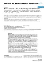
Figure 1 Hip implants used in this study. (a) two-piece Modular and
(b) single-piece Monoblock. Dimensions were measured by the au-
thors and may differ slightly from those provided by the manufacturer.
Photographs are not to scale relative to one another.
(a) (b)
Bougherara et al. Journal of Orthopaedic Surgery and Research 2010, 5:34
/>Page 3 of 12
Vashon, WA, USA) was developed earlier [14-16]. Com-
puterized tomography (CT) scans were performed every
0.5 mm along the synthetic femur and exported in Solid-
Works CAD software. The CAD model contained sur-
faces representing cortical and cancellous bone, but had
no intramedullary canal. The canal was created by cutting
away cancellous bone. The femur had a proximal step-like
section removed of 95 mm distal-proximal length and 16
mm medial-lateral width. This simulated traumatic, path-
ological, or surgically-generated bone loss during or fol-
lowing total hip replacement surgery in scenarios where
there may be no supportive proximal femoral bone and
the diaphyseal structural support is compromised or
minimal. This may be augmented by a bone graft in order
to restore the greater trochanter and/or abductor muscle
attachment.
Although the FE model of the femur could have been
based on CT scans of a human femur, the authors chose
to use a synthetic femur for the following reasons,
namely, the synthetic femur's mechanical properties have
been validated against human femurs previously, the FE
model of the synthetic bone was already available to the
authors, the inter-specimen uniformity of the synthetic
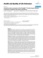
Figure 2 CAD models for hip implants alone (Construct A). (a)
Modular and (b) Monoblock devices were each placed in rigid blocks
distally and then proximally subjected to 700 and 2000 N axial loads us-
ing a flat plate during FE analysis. The same flat plate was used in ap-
plying load in FE analysis for the hip implant-femur (Construct B). Large
arrows show vertical load direction.
(a)
(b)
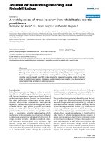
Figure 3 FE mesh models for hip implant-femur (Construct B). (a)
Modular and (b) Monoblock devices. Femurs had a proximal step-like
cut to simulate bone loss from trauma, pathology, and/or surgical
shaping. Vertical force applicator and rigid distal fixation are not
shown. Posterior view is shown.
(a) (b)
Bougherara et al. Journal of Orthopaedic Surgery and Research 2010, 5:34
/>Page 4 of 12
femurs would allow for ease-of-comparison to future FE
and experimental studies using this often-used commer-
cially-available synthetic bone, and the ease-of-storage
and lack of degradation of the synthetic bone permitted
the authors to frequently re-examine the bone itself dur-
ing the study, unlike cadaveric material.
Prior experimental validation of the same FE model of
the femur itself showed only moderate average differ-
ences between experimental and FE values for axial stiff-
ness (0% difference; cortical bone E = 9.1 GPa; intact
femur)[14], torsional stiffness (3.3% difference; cortical
bone E = 9.1 GPa; intact femur)[14], medial surface strain
(10% difference; cortical bone E = 10 GPa; intact
femur)[15], and medial surface strain (10.9% difference;
cortical bone E = 10 GPa; instrumented femur)[16].
The same geometry and material properties for the
femur were used in previous works [15,16]. In addition,
the same tetrahedral elements of identical shape and size
were employed to mesh the femur. Mesh sensitivity was
done on the model using a Workbench mesh tool called
"relevance", which indicates the minimum number of ele-
ments (coarse mesh, 0% relevance) to maximum number
of elements (very fine mesh, 100% relevance) possible to
discretize the femur. A preliminary investigation showed
that an 80% mesh relevance model of the femur had stress
and strain values less than 1% different from a 100% mesh
relevance model of the femur. Thus, an FE femur model
with 80% relevance was used presently. The number of
total elements used, of course, was different from previ-
ous works because the present model required removing
proximal bone to accommodate the total hip stems.
Femur-Implant Assembly
The femur-implant systems (Construct B) were created in
SolidWorks by assembling the individual models of the
femur, the implant, the cement square fixation block, and
the flat plate load applicator. The assembly was exported
to ANSYS Workbench 11.0 for FE analysis. The Work-
Bench "simulation" module automatically generates con-
tact between the assembled surfaces. CONTA174 in
ANSYS is a three-dimensional 8-node surface-to-surface
contact element that was used in this study. This type of
contact element was located on a deformable surface of a
three-dimensional solid element that contacts and slides
on a target surface, i.e., TARGE170 in this study.
CONTA174 had three degrees of freedom at each node,
namely, translations in the nodal x, y, and z directions. It
had the same geometric characteristics as the solid ele-
ment face with which it was connected. Contact occurred
when the element surface penetrated its associated target
element, i.e., TARGE170. CONTA174 and TARGE170
shared the same real constants. All contact elements were
set to fully bonded, which in reality is equivalent to a
coefficient of friction of 1. Bonded contact was used to
simulate full bony ongrowth and long-term mechanical
stability.
The FE model of the flat plate load applicator was cre-
ated using a 20-node structural solid containing 52791
nodes and 11924 elements (Figure 2). It was assigned
material properties of steel (E = 200 GPa, ν = 0.3). The flat
plate had a 20 mm thickness and a 70 mm diameter. A
force defined by a vector was applied on the top surface of
the flat plate, resulting in a 700 or 2000 N axial load.
These loads acted to apply a vertical force onto the metal-
lic femoral ball of both hip implants. The movement of
the flat plate was restricted in all directions, except in the
vertical direction. This arrangement was used for both
Constructs A and B.
Meshing and material properties
ANSYS Workbench 10.0 was used to generate meshes.
For Construct A, the number of nodes and elements was
41098 and 29436 (Modular) and 33270 and 23744
(Monoblock). For Construct B, the number of nodes and
elements was 52121 and 39423 (Modular) and 61577 and
45847 (Monoblock). Body elements included 10-node
quadratic tetrahedrons for cortical bone, cancellous
bone, and implants, and a 20-node quadratic hexahedron
for the axial force applicator. Contact elements were qua-
dratic triangular for cortical bone, cancellous bone, and
implants, and quadratic quadrilateral for the axial force
applicator. Synthetic femurs were isotropic and linearly
elastic, with material properties for cortical (E = 10 GPa,
ν = 0.3) and cancellous (E = 206 MPa, ν = 0.3) bone based
on prior studies [14-16]. Young's Modulus for cortical
bone (E = 10 GPa) was an average of compressive (7.6
GPa) and tensile (12.4 GPa) values [15]. The Modular
stem is made from a titanium-based substrate that has
been surface hardened but whose properties are proprie-
tary information (U.S. Patents 5,192,323 and 5,326,362)
and Ti-6Al-4V, a well-known industrially used titanium-
based product. The Monoblock stem, however, is manu-
factured solely from Ti-6Al-4V. Titanium-based alloys
have a typical Young's modulus range of 100 to 120 GPa.
Thus, material properties for both of these titanium-
based implants were set in the middle of the range for
titanium alloy (E = 110 GPa, ν = 0.36). The femoral balls
were set for cobalt-chrome (E = 200 GPa, ν = 0.3).
FE analysis
FE analysis was done using ANSYS Workbench 10 suite
to replicate experimental conditions. For Construct A,
experimental cement potting of the hip stems was mim-
icked in the Simulation utility by constraining the distal
25 mm of the stem lengths. For Construct B, the displace-
ment of the distal end of the femur was restrained by
assigning displacement restrictions on the distal faces of
the femur. Vertical forces were applied at the face of the
applicator with motion restricted in all but the axial
direction (i.e., z-axis). Bonded contact was modeled
Bougherara et al. Journal of Orthopaedic Surgery and Research 2010, 5:34
/>Page 5 of 12
between all contact surfaces, namely, bone-implant,
implant-cement, and implant-implant interfaces. Also,
the contact region between the vertical load applicator
and cobalt-chrome femoral ball was bonded with no slip-
ping. The FE models for Construct B (hip stems
implanted into femurs) mimicked the long-term stability
of the implants. The bone-implant interfaces, modeled as
fully bonded, would be representative of the bony
ongrowth around the hip stems that would be expected to
occur over the long-term.
Experimental Methodology
General test parameters
The FE model of Construct A was validated with
mechanical tests at 700 and 2000 N of axial load (Figure
4). Axial load levels were similar to those previously used
for intact femurs and hip implant-femur constructs [14-
22].
Hip implant preparation
Distal ends of the hip prostheses were placed into square
steel chambers filled with cement. Implants were posi-
tioned vertically and inserted so the working lengths were
225 mm. Implants were instrumented with 350 Ohm lin-
ear strain gages (Model CEA-06-125UW-350, Vishay
Measurements Group, Raleigh, NC, USA). Each prosthe-
sis had 8 gages fixed along medial and lateral surfaces.
Because of differing geometries and surface texturing of
the implants, strain gage locations could only be placed
approximately at corresponding points. Wire leads from
each gage were attached to an 8-channel Cronos-PL data
acquisition system (IMC Mess-Systeme GmbH, Berlin,
Germany). FAMOS V5.0 software (IMC Mess-Systeme
GmbH, Berlin, Germany) was used for data storage and
analysis.
Mechanical testing
Experiments were performed using an Instron 8874
(Canton, MA, USA) with a capacity of ± 25 kN, a resolu-
tion of 0.1 N, and an accuracy of ± 0.5%. Hip implants had
a cobalt-chrome femoral ball (diameter, 26 mm) and were
distally secured with a vice. A vertical load was applied
using a flat metal plate under displacement control (dis-
placement ≤ 0.5 mm; rate = 5 mm/min; preload = 50 N).
The slope of the "ramp-up" force-displacement curve was
the axial stiffness. This was repeated three times, and an
average value was computed.
Strain gage measurement
A second series of tests on each implant achieved 700 and
2000 N axial loads. Based on initial implant stiffness
obtained earlier, a maximum deflection was computed
and used to reach the desired axial force. Strain values
were recorded for a minimum of 60 seconds and averaged
with little variation during this period. Tests were done
with the same preload and loading rate described earlier
and were repeated three times at 700 and 2000 N axial
forces to obtain average strain for each gage. Load con-
trol, though usually used to achieve a fixed force, was
unstable at present; thus, all experiments were done with
displacement control.
Percentage Difference Calculations
For the implant alone (Construct A), the absolute values
of the differences between FE strains and experimental
measurements were calculated as % difference = (FE
strain - experimental strain)/experimental strain × 100.
For the implant-femur configuration (Construct B), load
sharing differences between the implant and the femur
were computed from FE data as % difference = (implant
peak strain - femur peak strain)/femur peak strain × 100
and % difference = (implant average stress - femur aver-
age stress)/femur average stress × 100, whereas the differ-
ences in implant peak stresses from FE were calculated as
% difference = (Monoblock - Modular)/Modular × 100.
Results
FE results for implant-femur configuration
The strain and stress distribution maps at 2000 N are
shown for the implant-femur Construct B (Figures 5 and
6). Peak implant strains exceeded those of the host femur
by 38% (Modular) and 39% (Monoblock). Peak implant
stresses were situated in the neck region, particularly for
Figure 4 Mechanical testing of hip implants alone (Construct A).
(a) Modular and (b) Monoblock devices. An indenting plate com-
pressed the femoral head. Implants were fixed in cement chambers to
a depth such that working lengths for both stems were 225 mm. Large
arrows show vertical load direction. Strain gages are indicated by num-
bered arrows.
(a) (b)
1
2
3
4
5
6
7
8
1
2
3
4
5
6
7
8
Bougherara et al. Journal of Orthopaedic Surgery and Research 2010, 5:34
/>Page 6 of 12
Figure 5 FE model strain distributions of hip prostheses virtually implanted in FE models of a femur (Construct B). (a) Modular hip stem, (b)
femur into which the Modular hip stem was inserted, (c) Monoblock hip stem, (d) femur into which the Monoblock hip stem was inserted. Strains
shown are equivalent elastic strain (Von Mises) in mm/mm units. Results are for 2000 N axial load. Posterior view is shown.
(a)
(b)
(c)
(d)
Bougherara et al. Journal of Orthopaedic Surgery and Research 2010, 5:34
/>Page 7 of 12
Figure 6 FE model stress distributions of hip prostheses virtually implanted in FE models of a femur (Construct B). (a) Modular hip stem, (b)
femur into which the Modular hip stem was inserted, (c) Monoblock hip stem, (d) femur into which the Monoblock hip stem was inserted. Stresses
shown are equivalent elastic stresses (Von Mises) in MPa units. Results are for 2000 N axial load. Posterior view is shown.
(c)
(d)
(a)
(b)
Bougherara et al. Journal of Orthopaedic Surgery and Research 2010, 5:34
/>Page 8 of 12
the Modular on the stem at its body-stem junction (Fig-
ure 7). The Modular peak stresses exceeded that of the
Monoblock implant by 34%. Average implant stress,
excluding the peaks, ranged from 0 to 85 MPa (Modular)
and 0 to 75 MPa (Monoblock). Both implants carried the
majority (Modular, 76%; Monoblock, 66%) of the 2000 N
axial force relative to the femur.
Experimental results for implant alone
For Construct A (implant alone), stiffness values for the
hip implants were 2476 N/mm (Modular) and 553 N/mm
(Monoblock), indicating a 4.5 times difference between
them. The linearity of the force-deflection data (Modular,
R
2
= 0.968; Monoblock, R
2
= 0.997) showed that the spec-
imens remained within the linear elastic region, incurring
no permanent deformation during mechanical stiffness
tests. Strain distributions obtained from experiments on
the hip prostheses are shown (Table 1). By dividing strain
values of corresponding Locations 1 to 8 at 2000 N by
strain values at 700 N, the average strain ratios of 3.3
(Modular) and 3.2 (Monoblock) were obtained. These
ratios were close to the ratio of the axial loads themselves
(= 2000 N/700 N = 2.9). By dividing strain values of corre-
sponding Locations 1 to 8 for the Monoblock by the
strain values for the Modular hip implant, the average
strain ratios of 3.1 (at 700 N) and 2.9 (at 2000 N) were
obtained. This indicates that the Modular prosthesis was
about 3 times stiffer than the Monoblock.
Validating the FE model using experimental results
For Construct A, the percentage difference between the
FE model and experimental strain at Locations 1 to 8
were calculated as described earlier. For the Modular hip
implant data (Table 1), the average differences for Loca-
tions 1 to 8 at axial loads of 700 and 2000 N, respectively,
were 3.8 ± 3.2% (range, 0-9.0%) and 2.4 ± 1.7% (range, 0.2-
4.9%). For the Monoblock hip implant data (Table 1), the
average differences for Locations 1 to 8 at axial loads of
700 and 2000 N, respectively, were 28.1 ± 25.4% (range,
1.1-58.6%) and 28.6 ± 28.7% (range, 0.1-58.1%), with an
overall average difference of 28.3 ± 26.2%. However, the
Monoblock FE model was much more predictive for
proximal Locations 1, 2, 5, and 6 (average % difference =
3.2 ± 2.8%), rather than for distal Locations 3, 4, 7, and 8
(average % difference = 53.4 ± 4.2%).
FE-predicted versus experimentally-measured strains
for Construct A at 700 and 2000 N are graphically shown
(Figures 8 and 9). The slopes and linearity coefficients
(R
2
) of the lines-of-best-fit for all Modular and proximal
Monoblock experimental strain values showed nearly
perfect agreement with FE analysis, since results were
close to the ideal values of slope = 1 and R
2
= 1. Poor
agreement of "outliers" for the Monoblock stem was
caused by the visually observed (but unmeasured) medial
slippage of the femoral ball under the load application
plate that resulted in exaggerated experimental strains.
This medial motion of the femoral head was not consid-
ered in the FE model.
Discussion
FE model validation using experiments
The present three-dimensional FE model was validated
experimentally for the hip implant alone (Construct A) at
loads of 700 and 2000 N, showing reasonable agreement
(Table 1). The Modular implant showed an overall aver-
age difference for all locations of 3.0% between FE and
experimental values. The Monoblock device showed an
average difference of 3.2% for the proximal Locations 1, 2,
5, and 6; however, the average difference was 53.4% for
the distal Locations 3, 4, 7, and 8. This can be attributed
to the medial slip of the femoral head under the load
application plate that was visually observed (but not mea-
sured) during experiments, since motion was not con-
strained in this direction, causing exaggerated distal
strains in the Monoblock device. This was not replicated
in the FE model. In addition, it is likely that the lower
stiffness Monoblock stem underwent medial slip more so
than the higher stiffness Modular stem.
Modular versus Monoblock hip implants
For Construct A (Table 1), FE and experimental strains
showed that the Modular implant was about 3 times
mechanically stiffer than the Monoblock, and the stiff-
ness measurements showed the Modular device to be 4.5
times stiffer. This was most likely due to the difference in
geometry of the devices with respect to their cross-sec-
tional diameters in the transverse plane for the distal two-
thirds of their lengths, namely, Modular (range, 16.5 to
20.2 mm) and Monoblock (range, 15.4 to 16.3 mm) (Fig-
Figure 7 Stress map of the Modular hip stem at the modular junc-
tion. Under 2000 N axial load, a stress concentration is present at the
modular junction. Stresses shown are equivalent elastic stresses (Von
Mises) in MPa units.
Bougherara et al. Journal of Orthopaedic Surgery and Research 2010, 5:34
/>Page 9 of 12
ure 1). The material properties of the stems were virtually
identical, since they were both made from titanium-based
alloys. In the FE model, in fact, both implants had identi-
cal material properties assigned to them. Higher implant
stiffness may create an implant-femur construct with an
increased stiffness that provides enhanced mechanical
stability in the immediate post-operative situation, but it
may create eventual femur stress shielding and bone loss
[23]. Conversely, lower device stiffness may result in
increased load transfer to the host femur, subsequently
stimulating bone ingrowth around the implant, minimiz-
ing bone loss due to resorption, and improving mechani-
cal stability in the long-term [23-27].
For Construct B (Figure 6a and 6c), FE results showed
that there was better overall load transfer to the whole
femur and, thus, less load absorption by the Monoblock
stem itself (0-75 MPa, excluding peaks) compared to the
Modular implant (0-85 MPa, excluding peaks). Therefore,
the Monoblock prosthesis might facilitate greater load
transfer to the femur, potentially promoting increased
bone ingrowth around the implant and reducing bone
remodeling and resorption [23-27]. Conversely, the Mod-
ular device carried a greater amount of load, making it is
less conducive to biomimetic performance in the patient
femur. Moreover, the FE results identified a stress con-
centration on the stem at the modular junction of the
Modular implant (Figure 7). This could make it suscepti-
ble to fracture clinically, in which the load levels may be
elevated compared to that currently used, especially dur-
ing higher impact activities which patients might choose
to perform [21].
Comparison of strains to prior studies
No earlier studies have examined the mechanical charac-
teristics of the present Modular and Monoblock
implants. However, comparison of current results to
prior experiments on primary hip prostheses may be
instructive. Waide and colleagues [28] found that experi-
mental compressive microstrains on the medial side
peaked at 756 for Muller-Curved and 765 for Lubinus
SPII hip prostheses cemented into synthetic femurs. Akay
and Aslan [20] measured experimental peak microstrains
for hip implants cemented into synthetic femurs, held in
20 deg of adduction, and compressed with a 3000 N axial
force. They obtained microstrains of almost 4000
(medial) and 2500 (lateral) for a carbon-based composite
implant and about 1200 (medial) and 900 (lateral) for a
titanium alloy prosthesis. These are similar to experimen-
tal strains achieved at present for Construct A (Table 1)
and for FE analysis strains for Construct B (Figure 5) at
2000 N. Even so, proper inter-study comparison is diffi-
cult because of the variety of implant materials, implant
geometries, and experimental conditions used in the lit-
erature, resulting in a broad range of strain levels
achieved on implant surfaces.
Clinical implications
Prior clinical results showed no problems at the Modular
junction, though follow-up was limited to 2 and 5 years
Table 1: Strains for hip implant alone (Construct A) for validating the FE model.
Side Location Modular (EXP) Modular (FE) Monoblock (EXP) Monoblock (FE)
700 N 2000 N 700 N 2000 N 700 N 2000 N 700 N 2000 N
Medial 1 125 456 127 453 251 696 264 682
2 144 523 157 524 259 789 249 756
3 126 400 126 409 924 2966 482 1390
4 190 543 200 570 894 2927 471 1319
Lateral 5 76 288 77 276 274 780 277 781
6 80 274 82 268 188 677 172 673
7 119 349 128 361 947 3077 392 1288
8 290 767 298 776 821 2730 389 1221
Medial strains are compressive. Lateral strains are tensile. EXP = experimental values. FE = finite element analysis values.
Bougherara et al. Journal of Orthopaedic Surgery and Research 2010, 5:34
/>Page 10 of 12
[10,11]. Other clinical results showed that the junction is
a site for potential implant fracture, often being associ-
ated with proximal bone loss causing implant loosening
and increased surface stresses [29,30]. This agrees with
maximum stem strains noted presently for the Modular
device at its modular junction (i.e., at the proximal and
distal interface) (Figure 5). This may lead to premature
implant failure, especially at higher loads than those
examined at present [21]. The Modular device trans-
ferred higher loads to the distal half of the femur bone
itself (0-7.5 MPa, including peaks) than the Monoblock
device was able to achieve (0-6.9 MPa, including peaks)
(Figure 6b and 6d). As confirmed clinically [31,32],
increased load transfer to the distal femur could cause
bone densification around the distal implant tip and pos-
sible femur fracture. Conversely, the single-piece Monob-
lock implant had limited strain concentrations towards
the proximal neck with increasing strains cascading down
towards its distal end. This was punctuated by a peak
stress at the distal-most medial point near the cement
chamber. While this did not replicate a clinical scenario,
it did suggest that the Monoblock device offered more
anatomical loading than the Modular implant. Accord-
ingly, the Monoblock prosthesis may have replicated the
natural femur better, promoting superior load transfer.
Limitations
Firstly, only axial compression tests were assessed. The
hip device would clinically be exposed to dynamic forces
exceeding the 700 and 2000 N used presently due to mus-
cle action and activities of daily living [21,33]. Given iden-
tical host bone quality, muscle activity, and soft tissue
constraint, each of which have an influence on the
dynamic forces and moments experienced by the bone-
implant construct, it is anticipated that the relative per-
formance reported of the Modular versus the Monoblock
hip prostheses would be similar in a "real world" clinical
scenario. However, the absolute values of stress and strain
obtained at present may not be reflective of in vivo
results. A direct biomechanical comparison between the
stems in vivo would be required to demonstrate these
postulations conclusively.
Secondly, the FE model used to assess Construct B
assumed that the synthetic femur had linear isotropic
mechanical properties. This simplified the analysis signif-
icantly. However, nonlinearity, anisotropy, and viscoelas-
ticity may influence bulk mechanical behavior of the
bones. Even so, comparison of FE analysis, synthetic
femurs, and human cadaveric femurs previously per-
formed by some of the authors [14] showed that linear
behavior is a good approximation of the femurs in axial
Figure 8 FE-predicted versus experimentally-measured strains
for Construct A at 700 N. Positive values indicate tension, while neg-
ative values indicate compression. The slope and linearity coefficients
(R
2
) of the line-of-best-fit for all Modular and proximal Monoblock
strain gages are given. Perfect agreement between FE and experi-
ments would yield slope = 1 and R
2
= 1. Outliers are gage Locations 3,
4, 7, and 8 on the distal portion of the Monoblock stem which demon-
strated exaggerated experimental strain due to femoral ball move-
ment in the medial direction under the load application plate.
MODULAR
MONOBLOCK
SLOPE = 0.98
R² = 0.99
-1000
-800
-600
-400
-200
0
200
400
600
800
1000
-1000 -500 0 500 1000
FE STRAIN
EXPERIMENTAL STRAIN
STRAIN COMPARISON (CONSTRUCT A, 700 N)
Ɣ
ż
OUTLIERS
OUTLIERS
Figure 9 FE-predicted versus experimentally-measured strains
for Construct A at 2000 N. Positive values indicate tension, while neg-
ative values indicate compression. The slope and linearity coefficients
(R
2
) of the line-of-best-fit for all Modular and proximal Monoblock
strain gages are given. Perfect agreement between FE and experi-
ments would yield slope = 1 and R
2
= 1. Outliers are gage Locations 3,
4, 7, and 8 on the distal portion of the Monoblock stem which demon-
strated exaggerated experimental strain due to femoral ball move-
ment in the medial direction under the load application plate.
MODULAR
MONOBLOCK
SLOPE = 1.00
R
2
=0.99
-4000
-3000
-2000
-1000
0
1000
2000
3000
4000
-4000 -3000 -2000 -1000 0 1000 2000 3000 4000
FE STRAIN
EXPERIMENTAL STRAIN
STRAIN COMPARISON (CONSTRUCT A, 2000 N)
Ɣ
ż
OUTLIERS
OUTLIERS
Bougherara et al. Journal of Orthopaedic Surgery and Research 2010, 5:34
/>Page 11 of 12
compression and torsion. Moreover, these assumptions
have been used in the literature previously for synthetic
femur FE modeling [14-16,26].
Thirdly, FE analysis had limited success in assessing the
experimental performance at the distal end of the Mono-
block device for Construct A. This was likely due to the
visual observation that the implant shifted medially
under the load application plate, since motion was not
constrained in that direction, thereby exaggerating distal
strains. This was not replicated in the FE analysis. More-
over, it is possible that the lower stiffness Monoblock
stem underwent such medial slip more so than the higher
stiffness Modular stem. Nonetheless, the FE model was
able to replicate all Modular strains and proximal Mono-
block strains to within about 3% of experimental data.
Fourthly, the FE model mimicked long-term bone
ongrowth around the stem and mechanical stability by
employing bonded contact at all implant-bone, implant-
cement, and implant-implant interfaces, i.e., bone
absorption/apposition was neglected. However, in actual-
ity, ongoing bone remodeling over the life span of the
implant will alter implant-femur biomechanics. The cur-
rent FE model, in effect, only assessed the biomechanical
situation at one time point during the service life of the
hip stem.
Fifthly, equivalent Von Mises strains from FE analysis
were used for comparison to experimental values from
uniaxial linear strain gages. It could be suggested that a
more appropriate technique would have been to compare
only FE principal strains with linear strain gage results.
However, it must be noted that the current approach has
been used by some of the present authors and others in
prior studies of bone-implant biomechanics [15,16].
Moreover, the strain gages are physically large, so that
they actually detect the average surface strain over a given
area, which is different than the principal strain at a spe-
cific point. Furthermore, comparing equivalent Von
Mises strains from FE with experimental values may have
been especially appropriate for slightly curved surfaces,
i.e. Locations 1, 2, and 5, since the slightly curved uniaxial
strain gages were essentially providing an average reading
of strain along the length of an arc. Ideally, however,
rosette-type strain gage setups may be able to provide
more exact experimental readings for comparison to Von
Mises strains from FE analysis, especially when circum-
ferential strains are also of interest [19,20].
Finally, this study combined into an FE implant-femur
model (Construct B) separate FE models for the hip
implants alone presently and the synthetic femur from
prior investigations [14-16]. Although individual implant
and femur FE models have been validated, future work
may ideally include experimentally testing an actual
implant-femur construct. The reason the present authors
performed separate experimental validations of the FE
models for the stems alone and the femur alone was a
pragmatic one. Specifically, physically inserting hip stems
into the synthetic femur canal would have made strain
gage measurements along the surface of the hip stem
itself extremely difficult experimentally because of the
very fragile nature of strain gages (i.e. they easily peel or
shear off) and the confined space inside the canal (i.e.
there is little room to accommodate strain gage wiring).
In spite of these drawbacks, the main intention of this
study was only to provide a preliminary assessment of the
biomechanics of the Modular and Monoblock stems
upon which more comprehensive future work may be
built.
Conclusions
This is the first report of the biomechanical characteris-
tics of these particular two-piece Modular and single-
piece Monoblock revision hip implants. The FE model of
the hip implant alone (Construct A) was predictive of
experimental strains at all locations on the Modular
device, but only for the proximal portion in the Monob-
lock device. Significant differences in FE strains of the
two prostheses implanted in an FE femur model (Con-
struct B) signified a greater amount of stress absorption
by the Modular implant than in the Monoblock, suggest-
ing that the host femur may carry more of the load when
the Monoblock device is employed. A stress concentra-
tion on the Modular implant occurred at the modular
junction, which may be susceptible to failure; however, no
comparable potential failure points were identified on the
Monoblock prosthesis. Experiments on Construct A
showed that the Modular device was 3 to 4.5 times
mechanically stiffer than the Monoblock.
List of Abbreviations
Construct A: implant alone; Construct B: femur-implant
construct; E: Young's Modulus; EXP: experimental val-
ues; FE: finite element; R
2
: Pearson linear correlation
coefficient; ν: Poisson's ratio.
Competing interests
The authors declare that they have no competing interests.
Authors' contributions
HB, RZ, MP, and PZ were involved in initial study design, femur acquisition, and
implant acquisition. HB, MM, and MP were involved in FE modeling and analy-
sis. RZ and SS were involved in specimen preparation, mechanical testing, and
data analysis. HB, RZ, and MM did the literature search, manuscript writing, fig-
ure preparation, and data analysis. MP and PZ did extensive re-reading of the
manuscript. PZ and EHS were involved in general supervision and consultation
of the project regarding clinical relevance. All authors approve of this final
manuscript version.
Acknowledgements
The authors thank Stryker (Mahwah, NJ, USA) and Zimmer (Warsaw, IN, USA) for
donating the hip implants used in this investigation. The investigators also
Bougherara et al. Journal of Orthopaedic Surgery and Research 2010, 5:34
/>Page 12 of 12
thank Kaveh Aminvaziri and Hooman Nouraei for drafting initial three-dimen-
sional geometries of the implants.
Author Details
1
Department of Mechanical and Industrial Engineering, Ryerson University,
Toronto, ON, M5B-2K3, Canada,
2
Martin Orthopaedic Biomechanics Laboratory,
St. Michael's Hospital, Toronto, ON, M5B-1W8, Canada,
3
Department of
Surgery, McMaster University, Hamilton, ON, L8S-4L8, Canada and
4
Department of Surgery, University of Toronto, Toronto, ON, M5G-1L5, Canada
References
1. Hall MJ, Owings MF: 2000 National Hospital Discharge Survey. Adv Data
2002, 329:1-18.
2. Furey MJ: Joint Lubrication. In Biomechanics: Principles and Application
Edited by: Peterson DR, Bronzino JD. Boca Raton, USA: CRC Press; 2008:4-
1-4-25.
3. Wheeless' Textbook on Orthopaedics [http://
www.wheelessonline.com]
4. Cameron HU: Modular junctions. Orthopedics Sep 2005, 28(9
Suppl):S1057-1058.
5. Fink B, Grossmann A, Schubring S, Schulz MS, Fuerst M: Short-term results
of hip revisions with a curved cementless modular implant in
association with the surgical approach. Arch Orthop Trauma Surg 2009,
129(1):65-73.
6. Gacon G, Philippe MP, Ray A, Hummer J, Hourlier H, Dambreville A:
[Metaphyseal and diaphyseal modular femoral implants implanted
without cement] [Article in French]. Rev Chir Orthop Reparatrice Appar
Mot 2001, 87(4):331-339.
7. Garcia-Rey E, Muñoz T, Montejo J, Martinez J: Results of a
Hydroxyapatite-Coated Modular Femoral Stem in Primary Total Hip
Arthroplasty. A Minimum 5-Year Follow-Up. J Arthroplasty 2008,
23(8):1132-1139.
8. Lombardi AV Jr, Berend KR, Mallory TH, Adams JB: Modular calcar
replacement prosthesis with strengthened taper junction in total hip
arthroplasty. Surg Technol Int 2007, 16:206-209.
9. Middleton RG, Howie DW, Costi K, Sharpe P: Effects of design changes on
cemented tapered femoral implant fixation. Clin Orthop Relat Res 1998,
355:47-56.
10. Cherubino P, Surace MF, Zatti G: [Implant revision: special implant
versus primary device.] [Article in English, Italian]. Chir Organi Mov
2003, 88(3):281-284.
11. Kang MN, Huddleston JI, Hwang K, Imrie S, Goodman SB: Early outcome
of a modular femoral component in revision total hip arthroplasty. J
Arthroplasty 2008, 23(2):220-225.
12. Zimmer []
13. Stryker []
14. Papini M, Zdero R, Schemitsch EH, Zalzal P: The biomechanics of human
femurs in axial and torsional loading: comparison of finite element
analysis, human cadaveric femurs, and synthetic femurs. J Biomech Eng
2007, 129(1):12-19.
15. Cheung G, Zalzal P, Bhandari M, Spelt JK, Papini M: Finite element
analysis of a femoral retrograde intramedullary nail subject to gait
loading. Med Eng Phys 2004, 26(2):93-108.
16. Bougherara H, Zdero R, Miric M, Shah S, Hardisty M, Zalzal P, Schemitsch
EH: The Biomechanics of the T2 Femoral Nailing System: A Comparison
of Synthetic Femurs with Finite Element Analysis. Proc Instn Mech Engrs,
Part H: J Engineering in Medicine 2009, 223(H3):303-314.
17. Talbot M, Zdero R, Schemitsch EH: Cyclic Loading of Periprosthetic
Fracture Fixation Constructs. J Trauma 2008, 64(5):1308-1312.
18. Zdero R, Walker R, Waddell JP, Schemitsch EH: Biomechanical Evaluation
of Periprosthetic Femoral Fracture Fixation. J Bone Joint Surg Am 2008,
90(5):1068-1077.
19. Decking R, Puhl W, Simon U, Claes LE: Changes in strain distribution of
loaded proximal femora caused by different types of cementless
femoral implants. Clin Biomech 2006, 21:495-501.
20. Akay M, Aslan N: Numerical and experimental stress analysis of a
polymeric composite hip joint prosthesis. J Biomed Mater Res 1996,
31:167-182.
21. Bergmann G, Graichen F, Rohlmann A: Hip joint loading during walking
and running, measure in two patients. J Biomech 1993, 26(8):969-990.
22. Pedersen DR, Brand RA, Davy DT: Pelvic muscle and acetabular contact
forces during gait. J Biomech 1997, 30(9):959-965.
23. Sumner DR, Turner TM, Igloria R, Urban RM, Galante JO: Functional
adaptation and ingrowth of bone vary as a function of hip implant
stiffness. J Biomech 1998, 31:909-917.
24. Jacobs JJ, Sumner DR, Galante JO: Mechanisms of bone loss associated
with total hip replacement. Orthop Clin North Am 1993, 24:583-590.
25. Nishii T, Sugano N, Masuhara K, Shibuya T, Ochi T, Tamura S: Longitudinal
evaluation of time related bone remodeling after cementless total hip
arthroplasty. Clin Orthop Relat Res 1997, 339:121-131.
26. Speirs AD, Heller MO, Taylor WR, Duda GN, Perka C: Influence of changes
in stem positioning on femoral loading after THR using a short-
stemmed hip implant. Clin Biomech 2007, 22:431-439.
27. Van Rietbergen B, Huiskes R, Weinans H, Sumner DR, Turner TM, Galante
JO: The mechanism of bone remodeling and resorption around press-
fitted stems. J Biomech 1993, 26:369-382.
28. Waide V, Cristofolini L, Stolk J, Verdonschot N, Toni A: Experimental
investigation of bone remodeling using composite femurs. Clin
Biomech 2003, 18:523-536.
29. Pierson JL, Crowninshield RD, Earles DR: Fatigue fracture of a modular
revision femoral component: a report of forty cases. Am Acad Orthop
Surg, Annual Meeting, Washington, DC, 23-27 February, 2005 .
30. Crowninshield RD, Maloney WJ, Wentz DH, Levine DL: The role of
proximal femoral support in stress development within hip
prostheses. Clin Orthop Rel Res 2004, 420:176-180.
31. Gupta S, New AMR, Taylor M: Bone remodelling inside a cemented
resurfaced femoral head. Clin Biomech 2006, 21(6):594-602.
32. Theis JC, Ball C: Medium-term results of cementless hydroxyapatite-
coated primary total hip arthroplasty: a clinical and radiological
review. J Orthop Surg (Hong Kong) 2003, 11(2):159-165.
33. Duda GN, Heller M, Albinger J, Schulz O, Schneider E, Claes L: Influence of
muscle forces on femoral strain distribution. J Biomech 1998,
31:841-846.
doi: 10.1186/1749-799X-5-34
Cite this article as: Bougherara et al., A biomechanical assessment of modu-
lar and monoblock revision hip implants using FE analysis and strain gage
measurements Journal of Orthopaedic Surgery and Research 2010, 5:34
Received: 9 February 2010 Accepted: 12 May 2010
Published: 12 May 2010
This article is available from : http://www.j osr-online.com/ content/5/1/34© 2010 Bougherara et al; licensee BioMed Central Ltd. This is an Open Access article distributed under the terms of the Creative Commons Attribution License ( ), which permits unrestricted use, distribution, and reproduction in any medium, provided the original work is properly cited.Journal of Orthopaedic Surgery and Research 2010, 5:34