báo cáo hóa học:" The effect of abductor muscle and anterior-posterior hip contact load simulation on the in-vitro primary stability of a cementless hip stem" ppt
Bạn đang xem bản rút gọn của tài liệu. Xem và tải ngay bản đầy đủ của tài liệu tại đây (2.34 MB, 14 trang )
Park et al. Journal of Orthopaedic Surgery and Research 2010, 5:40
/>Open Access
RESEARCH ARTICLE
© 2010 Park et al; licensee BioMed Central Ltd. This is an Open Access article distributed under the terms of the Creative Commons At-
tribution License ( which permits unrestricted use, distribution, and reproduction in any
medium, provided the original work is properly cited.
Research article
The effect of abductor muscle and
anterior-posterior hip contact load simulation on
the in-vitro primary stability of a cementless hip
stem
Youngbae Park*
†1
, Carolyne Albert
†2
, Yong-San Yoon
1
, Göran Fernlund
3
, Hanspeter Frei
4
and Thomas R Oxland
5
Abstract
Background: In-vitro mechanical tests are commonly performed to assess pre-clinically the effect of implant design
on the stability of hip endoprostheses. There is no standard protocol for these tests, and the forces applied vary
between studies. This study examines the effect of the abductor force with and without application of the anterior-
posterior hip contact force in the in-vitro assessment of cementless hip implant stability.
Methods: Cementless stems (VerSys Fiber Metal) were implanted in twelve composite femurs which were divided into
two groups: group 1 (N = 6) was loaded with the hip contact force only, whereas group 2 (N = 6) was additionally
subjected to an abductor force. Both groups were subjected to the same cranial-caudal hip contact force component,
2.3 times body weight (BW) and each specimen was subjected to three levels of anterior-posterior hip contact load: 0,
-0.1 to 0.3 BW (walking), and -0.1 to 0.6 BW (stair climbing). The implant migration and micromotion relative to the
femur was measured using a custom-built system comprised of 6 LVDT sensors.
Results: Substantially higher implant motion was observed when the anterior-posterior force was 0.6BW compared to
the lower anterior-posterior load levels, particularly distally and in retroversion. The abductor load had little effect on
implant motion when simulating walking, but resulted in significantly less motion than the hip contact force alone
when simulating stair climbing.
Conclusions: The anterior-posterior component of the hip contact load has a significant effect on the axial motion of
the stem relative to the bone. Inclusion of the abductor force had a stabilizing effect on the implant motion when
simulating stair climbing.
Background
Loosening of femoral hip implants is a major problem in
total hip arthroplasty [1]. Clinical studies have shown that
early implant migration negatively affects the long term
performance of cementless femoral stems [2-4]. Excessive
micromotion at the bone-implant interface inhibits suc-
cessful bone ingrowth in cementless implants and may
therefore result in early implant loosening [5-7]. The
immediate post operative migration and micromotion
(primary stability) of different femoral stems have been
evaluated under simulated physiological loading in in-
vitro experiments [8-12]. Although it has not yet been
demonstrated for cementless stems, some cemented
stems with inferior clinical results have been shown to
also result in higher in-vitro micromotions [13], which
demonstrates the clinical relevance of these in-vitro tests.
The physiological loads acting on the head of a femoral
stem have been established by telemetric measurements
for daily activities such as walking and stair climbing [14-
17], while the muscle forces for these activities have been
estimated by numerical models [15,18-20]. It is challeng-
ing to include all hip contact and muscle forces acting on
the femur in an in-vitro test and simplified test setups
have therefore been used to simulate the biomechanical
* Correspondence:
1
Department of Mechanical Engineering, Korean Advanced Institute of
Science and Technology, Daejeon, Republic of Korea
†
Contributed equally
Full list of author information is available at the end of the article
Park et al. Journal of Orthopaedic Surgery and Research 2010, 5:40
/>Page 2 of 14
environment to which hip implants are subjected to post-
operatively. Some in-vitro studies have simulated the hip
contact force alone [9,11,12,21-23], while others included
one [24,25] or many muscle forces [8,10]. However, it is
not clear how these variations affect stem migration and
micromotion.
In particular, the precise effect of the abductor muscle
load (F
abd
) on the primary stability of uncemented stems
has not been demonstrated. Of all muscle groups, the
abductors have been shown to have the most pronounced
effect on femoral strains, increasing medial bending in
the proximal femur during gait [26-28]. There are, how-
ever, contradictory results concerning the effects of
including muscle loading on primary stability, and these
studies also incorporated more than one muscle group
such that the effect of the abductor muscles has not been
isolated. In an in-vitro study of cemented stems, the sim-
ulation of muscle forces (abductor, vastus lateralis, and
tensor fascia latae) resulted in a small and non-significant
reduction in migration compared with the hip contact
force applied alone [8]. On the other hand, in another in-
vitro study, the inclusion of muscle loads (abductor, ten-
sor fascia latae, ilio-tibial tract, vastus lateralis and vastus
medialis) increased migration and micromotion of a
cementless stem [10]. We hypothesise that simulation of
an abductor muscle force increases implant micromotion
and migration of cementless stems compared with hip
contact forces alone.
The effect of the anterior-posterior component of the
hip contact force (F
ap
) on implant primary stability has
also not been established definitely. In-vitro studies have
measured the torsional strength of cementless implant
fixation [29-31] and these values were found to approach
the torque levels measured in-vivo during stair climbing
[32] Physiological cranial-caudal loads, however, were not
applied in these in-vitro studies, which may underesti-
mate the torsional strength of the stem-femur constructs.
Studies have measured implant migration and micromo-
tion under varying F
ap
loads [10,24]. One study reported
higher distal migration and micromotion when simulat-
ing stair climbing compared to walking loads [10],
whereas the other did not observe a difference in distal
micromotion between stair climbing and single-leg
stance, a configuration without F
ap
[24]. These studies,
however, also varied muscular loading such that the effect
of F
ap
was not isolated. We hypothesise that the higher F
ap
load observed during stair climbing generates greater
implant-bone micromotion and migration compared
with walking.
To test our hypotheses, we conducted in-vitro tests on
composite femurs, in which we examined the effect of the
abductor on the motion of a cementless implant at three
levels of anterior-posterior hip contact load.
Methods
A cementless femoral stem (VerSys collarless size 14,
Zimmer Co., Dover, Ohio, USA) was implanted in twelve
composite femurs (Model 3303, Third Generation,
Pacific Research Laboratories, Vashon, Washington,
USA). The femoral cavity was prepared manually accord-
ing to the implant manufacturer's instructions, using
straight reamers and broaches. Visual inspection of the
cavity after preparation revealed that the regions of con-
tact between the stem and the cortical component of the
composite bones were consistent between specimens.
The specimens were cut at 27 cm from the proximal end
and the distal 6 cm were potted in dental stone (Tru-
Stone, Heraeus Kulzer, Armonk, New York). The speci-
mens were then loaded cyclically on a biaxial servohy-
draulic testing machine (Instron Model 8874, Instron,
Canton, Massachusetts). The loads applied were designed
to mimic walking and stair climbing loads as measured by
Bergmann et al. [15].
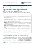
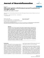
The specimens were divided into two groups for bio-
mechanical testing. Group 1 (N = 6, Figure 1a-b) was
loaded with the hip contact force only. A cranial-caudal
force (F
cc
) of 2.3 times body weight (BW) was applied by
the linear actuator, with the femur potted at 13° of adduc-
tion (Figure 1a), generating a proximal-distal component
of 2.2 BW and a medial-lateral component of 0.5 BW. A
body weight of 75 kg was used for the simulations. The
potted distal femur was fastened to a linear guide to avoid
a horizontal reaction force in the frontal plane. Group 2
(N = 6, Figure 1c-d) was additionally loaded with an
abductor muscle load (F
abd
). The F
abd
was applied with a
steel cable using a lever that was joined to the actuator
through a hinge (Figure 1c). The steel cable was attached
to the greater trochanter through a custom-moulded
polymethylmethacrylate (PMMA) cap. The cable passed
through a copper tube that was embedded into the
PMMA cap, and the cap was attached to the bone with a
4 mm diameter steel pin inserted anterior-posteriorly
through the greater trochanter. The same muscle attach-
ment cap was used for all specimens to obtain a repeat-
able muscle orientation relative to the femur. An F
abd
of
1.1 BW [20] was applied by adjusting the offset between
the actuator and the femoral head, d
off
, in proportion to
the muscle-to-femoral head lever arm, d
m
, see Figure 1c.
The measured d
m
varied between 46 and 50 mm, and d
off
was adjusted in proportion to d
m
to maintain the same F
cc
and F
abd
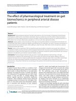
values between specimens. Based on equilibrium
calculations (shown in Figure 2), the same F
cc
orientation
as group 1 was achieved for group 2 by potting the femurs
at 4° of abduction.
For both groups, the anterior-posterior hip contact load
(F
ap
) was applied by the rotary actuator (M = F
ap
*d
off
). For
Park et al. Journal of Orthopaedic Surgery and Research 2010, 5:40
/>Page 3 of 14
group 1 d
off
was 32 mm, whereas in group 2 it was set at
0.83*d
m
, (and since d
m
ranged between 46 and 49 mm, d
off
therefore ranged between 38 and 41 mm). The F
ap
was
applied in three phases of 1000 cycles each. The first load
phase simulated walking without F
ap
(F
ap
= 0), the second
simulated walking with F
ap
(F
ap
= -0.1 to 0.3 BW), and the
third simulated stair climbing (F
ap
= -0.1 to 0.6 BW).
These peak F
ap
loads are based on published results of in-
vivo measurements [15]. During stair climbing, an actua-
tor rotation of approximately 1° in amplitude was
observed in the muscle group. Based on the geometry of
the implant and loading set-up, we estimate that this
rotation would have affected the orientation of the
abductor load relative to the femur by approximately 1°.
The applied peak loads for both groups are summarized
in Table 1. The loads were sinusoidal with a frequency of
1 Hz with in-phase peak loads.
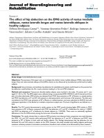
The relative motion between stem and bone was mea-
sured with a custom-built system similar to previously
published designs [33-35]. The system, illustrated in Fig-
ure 3, was comprised of six linear variable differential
transformers (LVDTs) mounted on a frame that was rig-
idly attached to the femur with seven set screws. The sen-
sors measured the three dimensional motion of a
triangular plate that was rigidly attached to the lateral
surface of the implant through a hole in the cortex. The
implant motion was calculated from the motion of the
triangle using a custom program implemented in Matlab
(MathWorks, Natick, Massachussetts). The measurement
resolution was smaller than 0.7 μm in all translational
directions, and smaller than 0.001° in rotation. The accu-
racy of the system in measuring translation was evaluated
against a micrometer precision dial gauge (Kafer, Ger-
many). Translation along each of the three axes was
applied to the implant, with the sensors attached to an
over-reamed composite femur. The maximum translation
error observed was 2 μm over a range of 30 μm (mean 0.8
μm, stdev 0.8 μm for 9 measurements), and 10 μm over a
range of 300 μm (mean 5.6 μm, stdev 3.0 μm for 9 mea-
surements). The accuracy of each sensor was also mea-
sured with a dial gauge (Kafer, Germany), where a
maximum error of 1.7 μm was observed over a range of
200 μm (mean 0.6 μm, stdev 0.4 μm for 60 measure-
ments). The rotation accuracy was evaluated analytically
from the maximum individual LVDT errors, yielding a
maximum rotation error of 0.0026°.
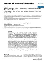
Migration was defined as the difference in stem mean
position (translations and rotations) between cycle 100
and the last cycle of each loading step, i.e. cycle 1000 (F
ap
= 0), cycle 2000 (F
ap
= 0.3 BW) and cycle 3000 (F
ap
= 0.6
BW), see Figure 4. The first 100 cycles were used for pre-
Figure 1 Loading set-ups. (a) Group 1 - no abductor, i.e. hip contact force alone. Axial and torsional loading of the actuator produced distal (F
d
), me-
dial (F
m
) and anterior-posterior (F
ap
) loading of the femoral head due to the mounting geometry and the offset between the femoral head and the
central axis of the actuator, d
off
(32 mm). (b) Resulting forces on the femur for group 1. (c) Group 2 - hip contact force and abductor. (d) Resulting forces
on the femur for group 2 (equilibrium calculations are presented in Figure 2).
(a) (b) (c) (d)
d
off
biaxial
actuator
load cell
cap
potting
linear guide
Instron table
cable clips
steel cable wire
PMMA cap
F
abd
(1.1BW)
F
cc
(2.3BW)
F
ap
(0 to 0.6BW)
F
ap
(0 to 0.6BW)
F
cc
(2.3BW)
13
q
13q
34q
d
off
d
m
4q
F
cc
F
m
F
d
13
q
Park et al. Journal of Orthopaedic Surgery and Research 2010, 5:40
/>Page 4 of 14
Figure 2 Equilibrium calculations for group 2 (abductor).
Where: F
a
force applied by the linear actuator
F
cc
cranial-caudal hip contact force on the femoral head,
i.e. resultant of the distal and the medial force components
F
abd
abductor force
We want: F
cc
= 2.3BW at 13° from the femur long axis, i.e. T
cc
=13°- T
b
F
abd
=1.1BW at 34° from the femur long axis, i.e. T
abd
=34°- T
b
Equilibrium on lever plate:
6F
x
= 0
F
abd
sin(34°-T
b
) – F
cc
sin(13°-T
b
) = 0
T
b
= -4°
6F
y
= 0
F
abd
cos(34°-T
b
) + F
a
– F
cc
cos(13°-T
b
) = 0
… F
a
= 1.33BW
6M = 0 (with femoral head as reference point)
F
abd
d
m
= F
a
d
off
… d
off
= 0.83 d
m
x
y
F
a
F
cc
F
abd
T
cc
T
abd
d
off
d
m
T
b
T
abd
F
a
F
a
M
xx
y
F
a
F
cc
F
abd
T
cc
T
abd
d
off
d
m
T
b
T
abd
F
a
F
a
M
Park et al. Journal of Orthopaedic Surgery and Research 2010, 5:40
/>Page 5 of 14
conditioning [10,12]. Micromotion was defined as the
average reversible motion of the stem during the last 200
cycles of each loading step, i.e. cycles 800-1000, 1800-
2000, and 2800-3000 (Figure 4). The migration and
micromotion were each comprised of 6 components:
translation along the medial, anterior and distal axes (at
the reference point shown in Figure 3), as well as rota-
tions projected in the frontal, sagittal and transverse
planes. The resultants of the three translational migration
and micromotion components are presented as 'total
translational migration' and 'total translational micromo-
tion'. Similarly, the terms 'total rotational migration' and
'total rotational micromotion' were used to represent the
resultant of all rotational components, and were defined
as the rotations about the helical axis [36].
The effects of F
abd
and F
ap
on each migration and micro-
motion component and their resultants were examined
with a two-way ANOVA, with F
ap
as a repeated measure,
followed by Student Newman Keuls post hoc analysis
with a significance level of 95%.
Results
The implant-bone migration and micromotion compo-
nents for both groups at all loading conditions are sum-
marized in Tables 2 and 3. The resultants of these
components, i.e. total translational and rotational migra-
tions and micromotions, are presented in Figures 5 and 6.
Migration occurred primarily along and about the
implant axis. Distal migration accounted for 94 to 99% of
the total translational migration. The average absolute
rotational migration was smaller than 0.04° in the sagittal
and frontal planes, but much larger in the transverse
plane (rotation about the implant axis) where it reached
an average of -1.2° and 0.4° for groups 1 and 2, respec-
tively. Micromotion, on the other hand, was generally not
dominated by motion in a specific direction.
Statistically, the abductor force F
abd
did not have a sig-
nificant main effect on the total translational migration (p
= 0.13), however, the total translational micromotion and
the total rotational migration and micromotion were on
average smaller with F
abd
than without F
abd
(p < 0.01), see
Figures 5 and 6. In contrast, the anterior-posterior hip
contact force component F
ap
had a clear significant main
effect on the total translational and rotational migrations
and micromotions (p < 0.01).
There was, however, a strong interaction between the
abductor and the F
ap
present in all the motion resultants
(p < 0.01) and all the components (p < 0.05), except the
rotational migration in the frontal plane (p = 0.38). In
general the abductor was only observed to affect the
implant motion at F
ap
0.6 BW. With this F
ap
, all compo-
nents of migration and micromotion were significantly
greater without the abductor (Tables 2 and 3). The only
motion components that were significantly affected by
the abductor at all F
ap
levels were the rotational migration
in the frontal plane, opposite in direction between the
two groups, and the translational micromotion in the lat-
eral axis, which was smaller for the abductor group.
Similarly, the effect of increasing F
ap
was mainly seen in
the no abductor group. Without the abductor, increasing
F
ap
from 0 to 0.3 BW increased the translational micro-
motion only in the lateral direction (p < 0.02). Increasing
F
ap
to 0.6 BW, however, led to significantly higher micro-
motion in all directions (p ≤ 0.01), higher translational
migration in all directions (p < 0.01), as well as higher
rotational migration in the transverse plane (p < 0.01).
With the abductor set-up, increasing F
ap
from 0 to 0.3 BW
did not significantly affect implant motion, and increas-
ing the F
ap
to 0.6 BW only gave a significant increase in
translational migration in the lateral and distal directions
Table 1: Loads applied to the hip system
Loading step Cycles Hip contact force (xBW) F
abd
F
cc
F
ap
(xBW)
Group 1 No abductor 1 1-1000 0.4 to 2.3 0 n/a
2 1001-2000 0.4 to 2.3 -0.1 to +0.3 n/a
3 2001-3000 0.4 to 2.3 -0.1 to +0.6 n/a
Group 2 Abductor 1 1-1000 0.4 to 2.3 0 1.1
2 1001-2000 0.4 to 2.3 -0.1 to +0.3 1.1
3 2001-3000 0.4 to 2.3 -0.1 to +0.6 1.1
F
cc
is in the caudal direction, and a positive F
ap
is in the posterior direction. The peak loads (maximum and minimum) were defined based on
published data [15], and scaled for a 70 kg individual.
Park et al. Journal of Orthopaedic Surgery and Research 2010, 5:40
/>Page 6 of 14
Figure 3 Motion measurement set-up. (a) LVDT set-up. (b) Coordinate system and sensor diagram. The reference point is located on the lateral side
of the stem, 113 mm proximal from the stem tip. The arrows show the location and direction of each sensor.
(a)
(b)
(c)
X
Z
Park et al. Journal of Orthopaedic Surgery and Research 2010, 5:40
/>Page 7 of 14
(p < 0.05), and rotational migration in the sagittal plane (p
< 0.01).
Discussion
In-vitro mechanical tests are commonly performed to
assess the effect of implant design on the stability of hip
endoprostheses pre-clinically. There is no standard pro-
tocol for these tests, and the loading conditions used vary
greatly. Efforts have been made to standardize the test
conditions [37], however, it is not clear how the abductor
muscle and the anterior-posterior hip contact force influ-
ence the translational and rotational stability of the
implant. The present study examined the effect of these
two parameters in the in-vitro assessment of cementless
hip implant primary stability.
As any biomechanical investigation this study has some
limitations. Composite femurs were used instead of
human femurs, and the implant motion was measured at
only one location. These two limitations are discussed in
detail in the following paragraphs. In addition, different
load magnitudes were applied in sequence to each speci-
men,. To minimize this effect on subsequent migration,
the study was designed such that the load magnitude was
applied in increasing increments simulating postopera-
tive rehabilitation. However, during a pilot test, the
micromotion observed during simulated walking was
similar whether these loads were applied before or after
the stair climbing cycles.
Composite femurs were used to minimize experimental
variability, as was done in other studies for the same rea-
son [13,23,38]. Their structural stiffness has been shown
to approximate that of natural bone, but with less vari-
ability [39,40]. No comprehensive study comparing
implant stability in composite versus cadaveric femurs
was found in the literature, however, in-vitro tests with
composite femurs [23] have yielded axial migration com-
parable to cadaveric femurs [41] for the CLS and press-fit
Muller implants.
Figure 4 Distal movement of the stem relative to the bone. Micromotion was calculated as the average amplitude of the cyclic motion during
the last 200 cycles of each loading step (F
ap
= 0, F
ap
= 0.3 BW, and F
ap
= 0.6 BW). Migration was the cumulative stem displacement at the end of each
step, with respect to its position at cycle 100.
0 500 1000 1500 2000 2500 3000
0
100
200
300
400
500
600
cycles
micrometer
Walking
Fap=0
Walking
Fap=0.3BW
Stair Climbing
Fap=0.6BW
100th cycle
Migration
Micromotion
Migration
Micromotion
Distal displacement (Pm)
Cycle
Walking
F
ap
= 0
Walking
F
ap
= 0.3BW
Stair climbing
F
ap
= 0.6BW
0 500 1000 1500 2000 2500 3000
0
100
200
300
400
500
600
cycles
micrometer
Walking
Fap=0
Walking
Fap=0.3BW
Stair Climbing
Fap=0.6BW
100th cycle
Migration
Micromotion
Migration
Micromotion
Distal displacement (Pm)
Cycle
Migration
Micromotion
Distal displacement (Pm)
Cycle
Walking
F
ap
= 0
Walking
F
ap
= 0.3BW
Stair climbing
F
ap
= 0.6BW
Park et al. Journal of Orthopaedic Surgery and Research 2010, 5:40
/>Page 8 of 14
In our tests, the implant motion was measured at a sin-
gle location. With the magnitude of physiological loads
applied, the stem and the bone could not be considered
rigid bodies; therefore the motion at other locations
could not be determined from our experimental data.
Some in-vitro studies have measured bone-implant
motion at multiple locations, as reviewed by Britton et al
[42], but the individual measurements are often limited
to a single axis (e.g [23,43]). Experimentally, space restric-
tions generally translate into having to choose between
measuring three-dimensional motion at limited locations
and measuring uniaxial motion at several locations. With
a single axis motion measurement approach, however,
rotational motions between the implant and the bone can
incur large errors in translational motion measurement,
which are proportional to the distance between the bone-
implant interface and the sensor axis. A six-degree of
freedom motion measurement device enabled us to avoid
such error, however, our motion measurements were lim-
ited to one location.
Two common testing set-ups were selected for this
study: the first set-up applied the hip contact force alone
while the second applied the hip contact force together
with the abductor force. The abductor force is often
included rather than other muscle groups because the
abductors were demonstrated to have the most important
effect of all muscle groups on stresses and strains in the
proximal femur [26,28]. More complex set-ups have been
used in the literature, but they are less common. For
example, in one study several muscle forces (abductor,
ilio-tibial band, tensor fascia latae, vastus lateralis and
vastus medialis) were simulated with multiple indepen-
dent actuators [10]. A set-up modeling the hip contact
force alone, on the other hand, is advocated for its sim-
Table 2: Migration results
Group 1 No abductor Group 2 Abductor
Component
F
ap
Average 95% CI Average 95% CI
Lateral translation (μm) 0 7 ± 4 5 ± 8
0.3 BW 17 ± 10 9 ± 13
0.6 BW
62
ab
± 18
20*
a
± 14
Anterior translation (μm) 0 -2 ± 7 0 ± 2
0.3 BW 7 ± 7 10 ± 20
0.6 BW
39
ab
± 26 19 * ± 16
Distal translation (μm) 0 50 ± 28 63 ± 43
0.3 BW 100 ± 52 103 ± 67
0.6 BW
385
ab
± 147
191*
ab
± 123
Sagittal plane rotation (×10
-3
°)
012± 75± 5
0.3 BW 30 ± 13 14* ± 7
0.6 BW
-8
ab
± 24
32*
ab
± 22
Frontal plane rotation (×10
-3
°)
015± 6-2*± 5
0.3 BW 34 ± 16 -10* ± 16
0.6 BW 25 ± 56 -14* ± 19
Transverse plane rotation (×10
-3
°)
0 34 ± 53 43 ± 55
0.3 BW -19 ± 144 175 ± 89
0.6 BW
-1175
ab
± 567 359* ± 172
* p < 0.05 compared to other group at same F
ap
level
a
p < 0.05 compared to same group at F
ap
= 0 BW
b
p < 0.05 compared to same group at F
ap
= 0.3 BW
Park et al. Journal of Orthopaedic Surgery and Research 2010, 5:40
/>Page 9 of 14
plicity and reproducibility. In a previous study [13], the
use of this simpler model was justified based on the
reported small effect of muscles on cement stresses in
cemented constructs [28].
Our measured distal migration/micromotion magni-
tudes for the VerSys FMT stem (walking: ~100 μm/10 μm
with both set-ups; and stair climbing: 191 μm/8 μm and
385 μm/16 μm with and without the abductor force,
respectively) were within the range of values reported for
other cementless implants tested in composite or cadaver
femurs. Distal migration/micromotion in the order of 150
μm/10 μm, 70 μm/30 μm, and 400 μm/50 μm were
reported in other studies [9,10,23] for the CLS stem, a
press-fit cementless implant similarly intended for proxi-
mal fixation. Stem migration measured clinically for the
CLS stem, however, is substantially larger (with an aver-
age in the order of 0.7 mm at 6 months) than the reported
values from in-vitro experiments [2,44]. This may be in
part due to the limited number of gait cycles modeled in-
vitro (usually 1000 or 5000 cycles) and/or the use of sim-
pler and lower loads compared to those sometimes seen
in-vivo, which may reach as high as eight times the body
weight during stumbling, for example [45]. Furthermore,
adaptation of the bone, i.e. remodelling and local bone
resorption, may also affect post-operative implant
motion. In-vitro tests could at best simulate resorption by
milling the bone interface at a predetermined location
prior to testing [46]. Nonetheless, the objective of in-vitro
primary stability tests for cementless stems is not to pro-
vide an estimate of in-vivo migration, but to ensure that a
favourable environment for successful bone ingrowth will
be achieved post-operatively. It has been proposed that
Table 3: Micromotion results
Group 1 No abductor Group 2 Abductor
Component
F
ap
Average 95% CI Average 95% CI
Lateral translation (μm) 0 7 ± 5 2* ± 2
0.3 BW
10
a
± 4 2* ± 3
0.6 BW
16
ab
± 5 2* ± 2
Anterior translation (μm) 0 4 ± 5 0 ± 4
0.3 BW 7 ± 9 -4 ± 16
0.6 BW
25
ab
± 8 -1* ± 19
Distal translation (μm) 0 11 ± 6 9 ± 3
0.3 BW 12 ± 6 9* ± 3
0.6 BW
16
ab
± 7 8* ± 2
Sagittal plane rotation (×10
-3
°)
0 0 ± 1 3 ± 5
0.3 BW 5 ± 5 3 ± 6
0.6 BW
11
ab
± 9 1* ± 5
Frontal plane rotation (×10
-3
°)
014± 610± 12
0.3 BW 20 ± 6 12 ± 16
0.6 BW
35
ab
± 11 10* ± 12
Transverse plane rotation (×10
-3
°)
0 -0± 2-1± 2
0.3 BW -6 ± 14 9 ± 16
0.6 BW
-61
ab
± 16 14* ± 37
* p < 0.05 compared to other group at same F
ap
level
a
p < 0.05 compared to same group at F
ap
= 0 BW
b
p < 0.05 compared to same group at F
ap
= 0.3 BW
Park et al. Journal of Orthopaedic Surgery and Research 2010, 5:40
/>Page 10 of 14
Figure 5 Implant migration resultants as a function of F
ap
for each group. (top) Total translational migration, i.e. (medial
2
+ anterior
2
+ distal
2
)
1/2
.
(bottom) Total rotational migration (about the helical axis). Results shown are means (N = 6) and 95% confidence intervals. * p < 0.05 compared to
the other group at the same F
ap
value.
a
p < 0.05 compared to the same group at F
ap
= 0 BW.
b
p < 0.05 compared to the same group at F
ap
= 0.3 BW.
Total translational migration
0
100
200
300
400
500
600
00.30.6
Fa p (x BW )
Migration (microns)
Group 1- no abductor
Group 2 - abductor
Total rotational migration
0
500
1000
1500
2000
00.30.6
Fa p ( x BW )
Rotation (x10-3 degrees)
Group 1- no abductor
Group 2 - abductor
F
ap
(xBW)
F
ap
(xBW)
ab
*ab
ab
*ab
Total translational migration
0
100
200
300
400
500
600
00.30.6
Fa p ( x BW )
Migration (microns)
Group 1- no abductor
Group 2 - abductor
Total rotational migration
0
500
1000
1500
2000
00.30.6
Fa p ( x BW )
Rotation (x10-3 degrees)
Group 1- no abductor
Group 2 - abductor
F
ap
(xBW)
F
ap
(xBW)
Total translational migration
0
100
200
300
400
500
600
00.30.6
Fa p ( x BW )
Migration (microns)
Group 1- no abductor
Group 2 - abductor
Total rotational migration
0
500
1000
1500
2000
00.30.6
Fa p ( x BW )
Rotation (x10-3 degrees)
Group 1- no abductor
Group 2 - abductor
F
ap
(xBW)
F
ap
(xBW)
ab
*ab
ab
*ab
Park et al. Journal of Orthopaedic Surgery and Research 2010, 5:40
/>Page 11 of 14
Figure 6 Implant micromotion resultants as a function of F
ap
for each group. (a) Total translational micromotion (b) Total rotational micromotion
(about the helical axis). Results shown are means (N = 6) and 95% confidence intervals. * p < 0.05 compared to the other group at the same F
ap
value.
a
p < 0.05 compared to the same group at F
ap
= 0 BW.
b
p < 0.05 compared to the same group at F
ap
= 0.3 BW.
Total translational micromotion
0
10
20
30
40
50
00.30.6
Fap (x BW)
Micromotion (microns)
Group 1 - no abductor
Group 2 - abductor
Total rotational micromotion
0
20
40
60
80
100
120
140
00.30.6
Fap (x BW)
Rotation (x10-3 degrees)
Group 1 - no abductor
Group 2 - abductor
F
ap
(xBW)
F
ap
(xBW)
ab
*
a
ab
*
a
a
*
Total translational micromotion
0
10
20
30
40
50
00.30.6
Fap (x BW)
Micromotion (microns)
Group 1 - no abductor
Group 2 - abductor
Total rotational micromotion
0
20
40
60
80
100
120
140
00.30.6
Fap (x BW)
Rotation (x10-3 degrees)
Group 1 - no abductor
Group 2 - abductor
F
ap
(xBW)
F
ap
(xBW)
Total translational micromotion
0
10
20
30
40
50
00.30.6
Fap (x BW)
Micromotion (microns)
Group 1 - no abductor
Group 2 - abductor
Total rotational micromotion
0
20
40
60
80
100
120
140
00.30.6
Fap (x BW)
Rotation (x10-3 degrees)
Group 1 - no abductor
Group 2 - abductor
F
ap
(xBW)
F
ap
(xBW)
ab
*
a
ab
*
a
a
*
Park et al. Journal of Orthopaedic Surgery and Research 2010, 5:40
/>Page 12 of 14
micromotion may be a better predictor than migration
for the long-term performance of femoral implants [47],
however, no clinical data was available to compare with
our micromotion results.
The high torsional F
ap
loads experienced by the proxi-
mal femur during stair climbing are well documented and
have been shown to occur during other activities such as
jogging, fast walking, and rising from a chair [32,48,49].
Concerns have been raised that these forces may exceed
the stem's torsional fixation strength [32]. However, these
concerns were based on comparisons with in-vitro tor-
sional strength assessments obtained without cranical-
caudal loading on the implant [29-31], which may have
underestimated the torsional strength under more physi-
ological loading. Torsional loading has been said to affect
the rotational motion of femoral hip implant [24,50]. One
of these studies, however, did not apply a cranial-caudal
load or measure the translational motion [49], while the
other varied not only the torsional load applied, but also
the muscle loads [24]. Our results indicate that for a col-
larless, cementless implant, increasing F
ap
not only
increases the axial rotation of the implant but that the
motion increases in other directions as well, particularly
distally. A similar finding was reported in another study,
in which stair climbing loads generated approximately
150 μm of distal migration, compared to 30 μm of proxi-
mal migration when simulating walking loads for the CLS
implant [10]. In their study, however, the F
ap
(~200N, i.e.
~0.3 BW for a 70 kg individual) was smaller than the val-
ues reported for stair climbing in-vivo, i.e. 0.6 BW [32]
and muscle forces also varied between their walking and
stair climbing set-ups [10]. Moreover, proximal migration
was observed under walking loads, which the authors
attributed to errors inherent in their motion measure-
ment system. The current study, on the other hand,
looked at the effect of F
ap
in isolation from other parame-
ters. Increasing F
ap
from 0 to 0.3 BW did not have a signif-
icant effect on implant motion, but a significant increase
in migration (mainly in the distal direction) was observed
when increasing F
ap
from 0.3 BW (walking) to 0.6 BW
(stair climbing) - this effect was largest without the
abductor. The micromotion also increased with increas-
ing F
ap
(mainly in the anterior direction), but this effect
was only seen without the abductor. Rotation was pri-
marily in the transverse plane, i.e. about the implant long
axis; without the abductor stair climbing produced on
average 10 times higher rotational micromotion (Table 3)
and 62 times higher rotational migration (Table 2) about
this axis compared to walking loads. Our results therefore
support our first hypothesis: the higher F
ap
loads
observed during stair climbing result in greater implant-
bone micromotion and migration compared with walk-
ing.
We found that inclusion of the abductor muscle force
stabilized the implant both in translation and rotation,
particularly when simulating stair climbing. This does
not support our second hypothesis. This observation,
however, is similar to another study in which inclusion of
muscles (abductor, tensor fascia latae and vastus lateralis)
resulted in less migration than did the hip contact force
alone for a cemented implant [8]. Nonetheless, there are
seemingly conflicting results in the literature; another
study reported that including muscle forces (abductor,
tensor fascia latae, vastus lateralis, and vastus medialis)
resulted in much greater motion than did the hip contact
force alone for the CLS cementless implant [10].
Although related debates[51], there is no clear explana-
tion on this conflicting result. We suspect that these dif-
fering observations may be related to differences in
medial-lateral bending moments in the femur, which are.
not only affected by the abductors, but also in great part
by the orientation of the hip contact force. In the study by
Kassi et al. [10], the hip contact force was applied at a 20°
angle from the long axis of the femur in the frontal plane,
whereas in the current study and that of Britton el al. [8]
it was applied at 13°. These two angles are within the
range reported from in vivo measurements [15,44,52], yet
they generate different bending moment distributions. At
13° from the femur axis [15], the hip contact force gener-
ates medial bending in the femur, which tapers to roughly
neutral bending around the implant tip, whereas at an
angle of 20° [44] it generates medial bending in the femur
around the proximal stem, but substantial lateral bending
at the implant tip. The abductor load generates an addi-
tional medial bending moment, which, when superposed
with the effect of the hip contact force, results in a more
pronounced medial moment when the hip contact force
is applied at 13° compared with when the force is applied
at an angle of 20°. Differences in implant-bone interface
contact stresses from the resulting bending moments
may explain why the muscle forces affected implant
motion differently between these studies. If this is the
case, the orientation of the hip contact force may be more
important than whether or not the abductor force is
included in in-vitro primary stability studies. Nonethe-
less, it is also possible that the effect of muscles on
implant motion is sensitive to the implant design.
The muscle attachment technique may also have
affected the implant motion. In one study [10] the femurs
were machined at the muscle insertion site which may
have artificially weakened the femur, possibly increasing
in the bone-implant motion. In the current study, the
abductor attachment was done through a polymethyl-
methacrylate that was fitted onto the greater trochanter,
and which may have reduced the motion by stiffening the
bone locally. Britton et al., however, also observed a
reduction in implant motion when adding muscle forces
Park et al. Journal of Orthopaedic Surgery and Research 2010, 5:40
/>Page 13 of 14
with woven polyethylene straps glued to the greater tro-
chanter, which is unlikely to have stiffened the bone [8].
Whether it is better to include or exclude the abductor
and/or other muscles during pre-clinical testing is debat-
able. It can reasonably be argued that including all mus-
cles provides a more physiologically representative
loading scenario. However, the question of how much
bending occurs physiologically is still being argued, e.g.
[53]. Inclusion of muscle forces also introduces a poten-
tial source of inter-specimen variability which could over-
shadow the effect of the variable being studied. Since
migration measured in-vitro is typically lower than
reported clinically, a set-up yielding higher bone-implant
motion could be considered as favourable for pre-clinical
testing. Based on our results, with the hip contact force
applied at 13° from the femur axis in the frontal plane,
maximum implant motion was observed when simulating
stair climbing without the abductor force.
Conclusions
Substantially higher rotational and translational implant
motion was observed when applying an anterior-poste-
rior hip contact force representative of stair climbing
loads versus walking loads. This difference, however, was
most prominent in the absence of the abductor muscle
force. We believe that the current study improves upon
previous research by examining the effect of the abductor
force and the anterior-posterior hip contact force on
implant primary stability under physiological cranial-
caudal loading and in isolation from other muscle groups.
Competing interests
The authors declare that they have no competing interests.
Authors' contributions
YP performed the design and execution of the experimental setup and analy-
sis, as well as drafted the manuscript. CA executed and analyzed the experi-
ment, performed statistical analsys as well as drafted the manuscript. YY
provided the design of the experimental setup, and participated in the intro-
duction and study design. GF provided important feedback on the experimen-
tal setup and partipated in the discussion. HF provided the design of the
experimental setup and participated in the discussion. TO provided important
feedback on the statistical analysis and participated in the discussion.
Author Details
1
Department of Mechanical Engineering, Korean Advanced Institute of Science
and Technology, Daejeon, Republic of Korea,
2
Orthopaedic and Rehabilitation
Engineering Center, Marquette University, Milwaukee, Wisconsin, USA,
3
Department of Materials Engineering, University of British Columbia,
Vancouver, Canada,
4
Department of Mechanical and Aerospace Engineering,
Carleton University, Ottawa, Canada and
5
Department of Mechanical
Engineering, University of British Columbia, Vancouver, Canada
References
1. Malchau H, Herberts P, Eisler T, Garellick G, Soderman P: The Swedish
Total Hip Replacement Register. J Bone Joint Surg Am 2002, 84-A(Suppl
2):2-20.
2. Freeman MA, Plante-Bordeneuve P: Early migration and late aseptic
failure of proximal femoral prostheses. J Bone Joint Surg Br 1994,
76(3):432-8.
3. Kobayashi A, Donnelly WJ, Scott G, Freeman MA: Early radiological
observations may predict the long-term survival of femoral hip
prostheses. J Bone Joint Surg Br 1997, 79(4):583-9.
4. Krismer M, Biedermann R, Stockl B, Fischer M, Bauer R, Haid C: The
prediction of failure of the stem in THR by measurement of early
migration using EBRA-FCA. Einzel-Bild-Roentgen-Analyse-femoral
component analysis. J Bone Joint Surg Br 1999, 81(2):273-80.
5. Engh CA, O'Connor D, Jasty M, McGovern TF, Bobyn JD, Harris WH:
Quantification of implant micromotion, strain shielding, and bone
resorption with porous-coated anatomic medullary locking femoral
prostheses. Clin Orthop 1992:13-29.
6. Jasty M, Bragdon C, Burke D, O'Connor D, Lowenstein J, Harris WH: In vivo
skeletal responses to porous-surfaced implants subjected to small
induced motions. J Bone Joint Surg Am 1997, 79(5):707-14.
7. Pilliar RM, Lee JM, Maniatopoulos C: Observations on the effect of
movement on bone ingrowth into porous-surfaced implants. Clin
Orthop 1986:108-13.
8. Britton JR, Walsh LA, Prendergast PJ: Mechanical simulation of muscle
loading on the proximal femur: analysis of cemented femoral
component migration with and without muscle loading. Clin Biomech
(Bristol, Avon) 2003, 18(7):637-46.
9. Buhler DW, Berlemann U, Lippuner K, Jaeger P, Nolte LP: Three-
dimensional primary stability of cementless femoral stems. Clin
Biomech (Bristol, Avon) 1997, 12(2):75-86.
10. Kassi JP, Heller MO, Stoeckle U, Perka C, Duda GN: Stair climbing is more
critical than walking in pre-clinical assessmnet of primary stability in
cementless THA in vitro. J Biomech 2005, 38(5):1143-54.
11. Monti L, Cristofolini L, Viceconti M: Methods for quantitative analysis of
the primary stability in uncemented hip prostheses. Artif Organs 1999,
23(9):851-9.
12. Nogler M, Polikeit A, Wimmer C, Bruckner A, Ferguson SJ, Krismer M:
Primary stability of a robodoc implanted anatomical stem versus
manual implantation. Clin Biomech (Bristol, Avon) 2004, 19(2):123-9.
13. Cristofolini L, Teutonico AS, Monti L, Cappello A, Toni A: Comparative in
vitro study on the long term performance of cemented hip stems:
validation of a protocol to discriminate between "good" and "bad"
designs. J Biomech 2003, 36(11):1603-15.
14. Brand RA, Pedersen DR, Davy DT, Kotzar GM, Heiple KG, Goldberg VM:
Comparison of hip force calculations and measurements in the same
patient. J Arthroplasty 1994, 9(1):45-51.
15. Bergmann G, Deuretzbacher G, Heller M, Graichen F, Rohlmann A, Strauss
J, Duda GN: Hip contact forces and gait patterns from routine activities.
J Biomech 2001, 34(7):859-71.
16. English TA, Kilvington M: In vivo records of hip loads using a femorsl
implant with telemetric output (a preliminary report). Journal of
Biomedical Engineering 1979, 1:111-115.
17. Rydell NW: Forces acting in the femoral head-prosthesis. Acta Orthop
Scand 1966:37-39.
18. Crowninshield RD, Brand R: Aphysiologically based criterion of muscle
force prediction in locomotion. Journal of Biomechanics 1981,
14(11):793-801.
19. Crowninshield RD, Johnston RC, Andrews JG, Brand RA: A biomechanical
investigation of the human hip. J Biomech 1978, 11(1-2):75-85.
20. Heller MO, Bergmann G, Deuretzbacher G, Durselen L, Pohl M, Claes L,
Haas NP, Duda GN: Musculo-skeletal loading conditions at the hip
during walking and stair climbing. J Biomech 2001, 34(7):883-93.
21. Claes L, Fiedler S, Ohnmacht M, Duda GN: Initial stability of fully and
partially cemented femoral stems. Clin Biomech (Bristol, Avon) 2000,
15(10):750-5.
22. Gotze C, Steens W, Vieth V, Poremba C, Claes L, Steinbeck J: Primary
stability in cementless femoral stems: custom-made versus
conventional femoral prosthesis. Clin Biomech (Bristol, Avon) 2002,
17(4):267-73.
23. McKellop H, Ebramzadeh E, Niederer PG, Sarmiento A: Comparison of the
stability of press-fit hip prosthesis femoral stems using a synthetic
model femur. J Orthop Res 1991, 9(2):297-305.
24. Burke DW, O'Connor DO, Zalenski EB, Jasty M, Harris WH: Micromotion of
cemented and uncemented femoral components. J Bone Joint Surg Br
1991, 73(1):33-7.
Received: 6 July 2009 Accepted: 24 June 2010
Published: 24 June 2010
This article is available from : http://www.j osr-online.com/ content/5/1/40© 2010 Park et al; licensee BioMed Central Ltd. This is an Open Access article distributed under the terms of the Creative Commons Attribution License ( ), which permits unrestricted use, distribution, and reproduction in any medium, provided the original work is properly cited.Journal of Orthopaedic Surgery and Research 2010, 5:40
Park et al. Journal of Orthopaedic Surgery and Research 2010, 5:40
/>Page 14 of 14
25. Callaghan JJ, Fulghum CS, Glisson RR, Stranne SK: The effect of femoral
stem geometry on interface motion in uncemented porous-coated
total hip prostheses. Comparison of straight-stem and curved-stem
designs. J Bone Joint Surg Am 1992, 74(6):839-48.
26. Cristofolini L, Viceconti M, Toni A, Giunti A: Influence of thigh muscles on
the axial strains in a proximal femur during early stance in gait. J
Biomech 1995, 28(5):617-24.
27. Finlay JB, Chess DG, Hardie WR, Rorabeck CH, Bourne RB: An evaluation of
three loading configurations for the in vitro testing of femoral strains
in total hip arthroplasty. J Orthop Res 1991, 9(5):749-59.
28. Stolk J, Verdonschot N, Huiskes R: Hip-joint and abductor-muscle forces
adequately represent in vivo loading of a cemented total hip
reconstruction. J Biomech 2001, 34(7):917-26.
29. Nunn D, Freeman MA, Tanner KE, Bonfield W: Torsional stability of the
femoral component of hip arthroplasty. Response to an anteriorly
applied load. J Bone Joint Surg Br 1989, 71(3):452-5.
30. Phillips TW, Nguyen LT, Munro SD: Loosening of cementless femoral
stems: a biomechanical analysis of immediate fixation with loading
vertical, femur horizontal. J Biomech 1991, 24(1):37-48.
31. Tanner KE, Bonfield W, Nunn D, Freeman MA: Rotational movement of
femoral components of total hip replacements in response to an
anteriorly applied load. Eng Med 1988, 17(3):127-9.
32. Bergmann G, Graichen F, Rohlmann A: Is staircase walking a risk for the
fixation of hip implants? J Biomech 1995, 28(5):535-53.
33. Berzins A, Sumner DR, Andriacchi TP, Galante JO: Stem curvature and
load angle influence the initial relative bone-implant motion of
cementless femoral stems. J Orthop Res 1993, 11(5):758-69.
34. Chareancholvanich K, Bourgeault CA, Schmidt AH, Gustilo RB, Lew WD: In
vitro stability of cemented and cementless femoral stems with
compaction. Clin Orthop 2002:290-302.
35. Park Y, Shin H, Choi D, Albert C, Yoon YS: Primary Stability of Cementless
Stem in THA Improved with Reduced Interfacial Gaps. J Biomech Eng
2008, 130(2):021008.
36. Kinzel GL, Hillberry BM, Hall AS Jr, Van Sickle DC, Harvey WM:
Measurement of the total motion between two body segments. II.
Description of application. J Biomech 1972, 5(3):283-93.
37. Cristofolini L, Vinteconti M: Towards the standardization of in vitro load
transfer investigations of hip prostheses. Journal of Strain Analysis for
Engineering Design 1999, 34(1):1-15.
38. Ebramzadeh E, Sangiorgio SN, Longjohn DB, Buhari CF, Dorr LD: Initial
stability of cemented femoral stems as a function of surface finish,
collar, and stem size. J Bone Joint Surg Am 2004, 86-A(1):106-15.
39. Cristofolini L, Viceconti M, Cappello A, Toni A: Mechanical validation of
whole bone composite femur models. J Biomech 1996, 29(4):525-35.
40. Heiner AD, Brown TD: Structural properties of a new design of
composite replicate femurs and tibias. J Biomech 2001, 34(6):773-81.
41. Schneider E, Eulenberger J, Steiner W, Wyder D, Friedman RJ, Perren SM:
Experimental method for the in vitro testing of the initial stability of
cementless hip prostheses. J Biomech 1989, 22(6-7):735-44.
42. Britton JR, Lyons CG, Prendergast PJ: Measurement of the Relative
Motion Between an Implant and Bone under Cyclic Loading. Strain
2004, 40(1):193-202.
43. Monti L, Cristofolini L, Toni A, Ceroni RG: In vitro testing of the primary
stability of the VerSys enhanced taper stem: a comparative study in
intact and intraoperatively cracked femora. Proc Inst Mech Eng [H] 2001,
215(1):75-83.
44. Davy DT, Kotzar GM, Brown RH, Heiple KG, Goldberg VM, Heiple KG Jr,
Berilla J, Burstein AH: Telemetric force measurements across the hip
after total arthroplasty. J Bone Joint Surg Am 1988, 70(1):45-50.
45. Bergmann G, Graichen F, Rohlmann A: Hip joint contact forces during
stumbling. Langenbecks Arch Surg 2004, 389(1):53-9.
46. Waide V, Cristofolini L, Stolk J, Verdonschot N, Toni A: Experimental
investigation of bone remodelling using composite femurs. Clin
Biomech (Bristol, Avon) 2003, 18(6):523-36.
47. Britton JR, Prendergast PJ: Preclinical testing of femoral hip components:
an experimental investigation with four prostheses. J Biomech Eng
2005, 127(5):872-80.
48. Hodge WA, Carlson KL, Fijan RS, Burgess RG, Riley PO, Harris WH, Mann
RW: Contact pressures from an instrumented hip endoprosthesis. J
Bone Joint Surg Am 1989, 71(9):1378-86.
49. Kotzar GM, Davy DT, Goldberg VM, Heiple KG, Berilla J, Heiple KG Jr, Brown
RH, Burstein AH: Telemeterized in vivo hip joint force data: a report on
two patients after total hip surgery. J Orthop Res 1991, 9(5):621-33.
50. Sugiyama H, Whiteside LA, Kaiser AD: Examination of rotational fixation
of the femoral component in total hip arthroplasty. A mechanical
study of micromovement and acoustic emission. Clin Orthop Relat Res
1989:122-8.
51. Cristofolini L, Viceconti M: J Biomech 2006, 39(16):3085-7. Comments on
"Stair climbing is more critical than walking in pre-clinical assessment of
primary stability in cementless THA in vitro" by Jean-Pierre Kassi, Markus
O. Heller, Ulrich Stoeckle, Carsten Perka, Georg N. Duda, Published on J.
Biomechanics 2005; 38: 1143-1154. author reply 3087-40.
52. Bergmann G, Graichen F, Rohlmann A: Hip joint loading during walking
and running, measured in two patients. J Biomech 1993, 26(8):969-90.
53. Taylor ME, Tanner KE, Freeman MA, Yettram AL: Stress and strain
distribution within the intact femur: compression or bending? Med Eng
Phys 1996, 18(2):122-31.
doi: 10.1186/1749-799X-5-40
Cite this article as: Park et al., The effect of abductor muscle and anterior-
posterior hip contact load simulation on the in-vitro primary stability of a
cementless hip stem Journal of Orthopaedic Surgery and Research 2010, 5:40