Biomedical Engineering Trends in Electronics Communications and Software Part 4 pot
Bạn đang xem bản rút gọn của tài liệu. Xem và tải ngay bản đầy đủ của tài liệu tại đây (2.96 MB, 40 trang )
Biomedical Engineering Trends in Electronics, Communications and Software
110
Partin, D. L.; Sultan, M. F.; Trush, Ch. M.; Prieto, R.; Wagner, S. J. (2006). Monitoring Driver
Physiological Parameters for Improved Safety, SAE World Congress, Detroit, USA,
ISBN 0-7680-1633-9
Shastri, D. (2008). Contact-free Stress Monitoring for User’s Divided Attention, Human
Computer Interaction, IN-TECH, Vienna, Austria, ISBN 978-953-7619-19-0, pp. 127-
134
Snel, J. (1999). Psychology of ban fruit, Psychoprof, ISBN 80-968083-2-X, Nove Zamky,
Slovakia
Treston. (2010). Pressure sensors with internal transmitter,
Tvarozek, V.; Novotny, I. ; Sutta, P. ; Flickyngerova, S. ; Shtereva, K. ; Vavrinsky, E. (2007)
Influence of Sputtering Parameters on Crystalline Structure of ZnO Thin Films.
Thin Solid Films, Vol. 515, 2007, pp. 8756-8760, ISSN 0040-6090.
Vavrinsky, E.; Stopjakova, V.; Brezina, I.; Majer, L.; Solarikova, P.; Tvarozek, V. (2010).
Electro-Optical Monitoring and Analysis of Human Cognitive Processes,
Semiconductor Technologies, IN-TECH, Vienna, Austria, ISBN 978-953-307-080-3,
pp. 437-462
Weis, M.; Danilla, T.; Matay, L.; Hrkut, P. , Kakos, J. (1995). Noninvasive Biomedical Sensors
on the Biology - Interface of Human Skin, 7th International Conference on
Measurement in Clinical Medicine, pp. 89-91, Stara Lesna, Slovakia
7
Wireless Communications and
Power Supply for In Vivo Biomedical
Devices using Acoustic Transmissions
Graham Wild and Steven Hinckley
Edith Cowan University
Australia
1. Introduction
Acoustic transmissions are investigated for use in the wireless transmission of digital
communications signals and power supply for in vivo biomedical devices. The acoustic
transmissions are intended to be used for fixed implanted biomedical devices, such as
pacemakers, but more importantly, neural implants were wired and wireless radio
frequency communications cannot be used. The acoustic transmissions can be used for both
wireless communications and to recharge the device, in vivo, using conventional
piezoelectric power harvesting techniques.
Current research in biomedical engineering is looking at implantable devices to regulate
conditions such as Parkinson’s and other neuromuscular conditions (Varadan, 2007).
Transient devices, such as those used in the gastrointestinal track, make use of high
frequency RF, were the permittivity of the human body begins to decrease (Kim et al., 2007).
However, significant power is still required. This results in local tissue heating, due to the
absorption of the electromagnetic radiation. This heating has side effects that limit the
exposure times for safe practices (Gabriel, 1996a; b; c). For neural implants, were the goal is
to have the product implanted for long periods of time, without complications and minimal
side effects, radio frequency communications cannot currently be used. Acoustic
transmissions represent an ideal low power method of communicating with in vivo
biomedical devices, and for recharging them through the use of piezoelectric based power
harvesting. Acoustic transmissions have previously been demonstrated as a means of
communicating through elastic solids, with applications to NDT and structural health
monitoring (Wild & Hinckley, 2010).
In this work, results presented show the general performance of the acoustic
communications channel and sample digital communications signals, through a biological
specimen, in vivo. The frequency response, transfer function, and transient response (at
resonance) of the communications channel were measured. Due to the frequency response
of the communications channel, phase shift keying has the best signal performance. To show
this, the three basic digital encoding methods were tested. Successful communication was
achieved through the communications channel using all three methods. The results support
the hypothesis that phase shift keying would be the best encoding method to utilise,
particularly in terms of signal robustness.
Biomedical Engineering Trends in Electronics, Communications and Software
112
Results of harvesting acoustic signals to provide power for recharging in vivo biomedical
devices are also presented. For the piezoelectric transducer used, we show the current-
voltage, and voltage-power characteristic curves. These are compared with theoretical
models of the power generation. Power requirements for pacemakers are discussed, and
how acoustic power harvesting could be successfully used to recharge the devices over their
respective lives.
2. Background
Biomedical devices implanted within the human body have been used since last century,
starting with the cardiac pacemaker. Cardiac pacemakers are a ubiquitous technology, with
over 3 million implanted worldwide (Wood & Ellenbogen, 2002). Since then, in vivo
biomedical devices have been utilised for further applications. The “pacemaker”, a term
now used as a general device that generates electrical pulses within the human body, has
been applied to the regulation of a number of conditions beyond their primary application
for cardiac arrhythmia. When used in the brain, the technique of alleviating the symptoms
of neurological disorders with electrical signals is called deep brain stimulation. Although
the use of direct brain stimulation began as early as 1947 (Hariz et al., 2010), the use of a
permanent pacemaker for deep brain stimulation is a much more recent development
(Varadan, 2007). These pacemakers for neurological conditions have been developed
recently primarily as a result of improve surgical and imaging techniques associated with
neurology (Elias & Lozano, 2010).
Elias and Lozano (2010), give an overview of the current applications of deep brain
stimulation. Neurological pacemakers have been applied in the brain for movement
disorders, including Parkinson’s disease, tremors, and dystonia. Also, they have been used
for the treatment of psychological problems such as depression and obsessive-compulsive
disorder. Current research on the topic is investigating the use of neurological pacemakers
for epilepsy, cluster headache, impaired consciousness, and morbid obesity. Pacemakers
have also been used for pain management, particularly pain associated with severe back
problems (Blain, 2009).
Currently, pacemakers have their batteries replaced after a five year period. Typically, the
entire pacemaker is removed, leaving the electrodes implanted. The battery life of a cardiac
pacemaker can be assessed using magnet electrocardiographic assessment. This can even be
performed over the telephone using transtelephonic monitoring (Schoenfeld, 2009). For
implantable cardioverter-defibrillators, radiofrequency transmissions are used in their
assessment, which has proven more effective than transtelephonic monitoring (Crossley et al.,
2009). However, the primary advantage of acoustic transmission is not only the ability to safely
conduct device follow-up for history taking, physical examination, electrocardiography,
radiography, interrogation, and reprogramming (Schoenfeld & Blitzer, 2008). Acoustic
transmissions will allow for in vivo recharging of the battery, reducing the number of surgeries
associated with pacemaker replacement, ideally down to zero, depending on the battery itself.
3. Theory
3.1 Piezoelectric transducer
For a complete understanding of piezoelectric materials and transducers, see Silk’s
Ultrasonic Transducers for Nondestructive Testing (1984). A brief overview is included here
for completeness.
Wireless Communications and Power Supply for
In Vivo Biomedical Devices using Acoustic Transmissions
113
The term piezoelectric means electricity from pressure. So as a force, either in the form of a
pressure or a stress (both measured in force per unit area), is applied to the transducer, an
electric signal is generated. Specifically, a charge dipole is generated within the crystal
structure of the material, which when used inside of a capacitor, results in the generation of
a voltage drop across the transducer.
In linear elastic solids, the strain (S) and stress (T) are related by the elastic stiffness (c). In
the same material, the electric displacement (D) is related to the electric field (E) by the
permittivity (ε
r
) of the material. These equations are referred to as the constitutive equations.
In a piezoelectric linear elastic material, the constitutive equations are coupled. Hence, a
change in stress or strain corresponds to a change in the charge distribution within the
material. The constitutive equations for a piezoelectric material are,
,
r
TcShE
D ε EhS
=+
=+
(1)
where h is the piezoelectric coupling coefficient.
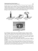
Fig. 1(a) shows the crystal lattice structure of lead zirconate titanate (PZT), a peizoceramic
material. As a force is applied to the crystal, the lattice is strained, and a charge dipole is
produced, similar to that seen in Fig. 1(b).
Fig. 1. Principle behind the use of a piezoelectric material, both before (a) and after (b) strain.
3.2 Digital communications
Due to the properties of the communications channel, only digital encoding methods have
been investigated. The primary benefit of digital encoding is improved fidelity. The three
basic digital encoding methods used include amplitude shift keying, frequency shift keying,
and phase shift keying. For the purpose of concept demonstration, only binary keying
methods were utilized.
3.2.1 Amplitude shift keying.
In amplitude shift keying, the digital information is encoded onto the analogue carrier as a
time varying signal of the amplitude. The simplest form of amplitude shift keying is on-off
keying, where a ‘1’ is represented by the amplitude function being maximum (on), and a ‘0’
Biomedical Engineering Trends in Electronics, Communications and Software
114
is represented by the amplitude function being zero (off). The on-off keying signal will have
the form,
(
)
(
)
()cos2 ,
c
ft At
π
ft=
(2)
where f
c
is the carrier frequency, and,
00
()
1.
for data
At
Afordata
=
⎧
=
⎨
=
⎩
(3)
On-off keying is decoded by using a rectifier and a low-pass filter that has a cut-off frequency
above the data rate, but below the carrier frequency. This removes the carrier wave component
(cos(2πf
c
t)) and recovers the amplitude function which is the digital signal (A(t)).
Fig. 2 shows the decoding process for an amplitude shift keying signal. Fig. 2 (a) shows the
data to be transmitted defined by (3); Fig. 2 (b) shows the on-off keying signal defined by
(2). The received signal is then rectified and low-pass filtered, to remove the carrier
frequency, shown in Fig. 2 (c). This also results in some distortion of the information signal
due to the removal of higher harmonics. Hence, the signal is passed through a comparator
to recover the digital information as shown in Fig. 2 (d).
Fig. 2. Decoding an amplitude shift keying signal, a) the digital data to be transmitted, b) the
on-off keying signal, c) the rectified low-pass filtered signal, d) digital information recovered
after a comparator.
3.2.2 Frequency shift keying.
In frequency shift keying the digital information is encoded onto the analogue carrier as a
time varying signal of the frequency. In binary frequency shift keying, two frequencies are
used; one frequency represents a digital ‘1’ and the second represents a digital ‘0’.
Frequency shift keying can be thought of as two interweaved on-off keying signals with
Wireless Communications and Power Supply for
In Vivo Biomedical Devices using Acoustic Transmissions
115
different carrier frequencies. This means that a similar non-coherent decoding method can
be used to recover the digital information. However, the advantage frequency shift keying
has over amplitude shift keying is lost in this way. To maintain the independence of the
signal from amplitude variations, a coherent detection method is used. Here, the received
signal is split into two separate, but identical signals; each of the form,
(
)
(
)
(
)
0
cos 2 ,
c
ft A
πf
tt=
(4)
where,
1
2
0
()
1.
c
ffordata
ft
ffordata
=
⎧
=
⎨
=
⎩
(5)
The two signals are each multiplied with a synchronous sinusoid, one with frequency f
1
, the
other with frequency f
2
. This shifts the signal to zero and 2f
n
. A low pass filter is used to
remove the 2f
n
component from each signal. The two filtered signals are then compared to
each other to recover the digital information.
In Fig. 3 we see the stages involved in the decoding of a frequency shift keying signal. The
data transmitted, Fig. 3 (a), is encoded as two separate frequencies in the signal, defined by
(4). The received signal is then split into two identical signals, each mixed with a sinusoid at
one of the two frequencies, shown in Fig. 3 (c). Here one of the data bits has no offset, while
the second bit has an offset. When filtered, the lack of an offset will result in a zero, while an
offset will give a one. The recovered signal after the filter and comparator is shown in Fig. 3
(d).
3.2.3 Phase shift keying.
In phase shift keying, the digital information is encoded onto the analogue carrier as a time
varying signal of the phase. Decoding phase shift keying uses some simple mathematics to
retrieve the phase information. The phase shift keying signal,
(
)
(
)
(
)
0
cos 2 ,
c
ft A ft t=+
πφ
(6)
where,
90 0
()
90 1,
for data
t
for data
−
=
⎧
=
⎨
=
⎩
φ
(7)
is multiplied by a synchronous sine and cosine, giving,
()
()
()
0
0
( ) cos(2 ( )) sin(2 )
[sin 4 ( ) sin ( ) ],
2
cc
c
ht A ft t ft
A
f
tt t
=
+×
=++
π
φπ
πφ φ
(8)
and,
()
()
()
0
0
( ) cos(2 ( )) cos(2 )
[cos cos 4 ( ) ].
2
cc
c
g
tA
f
tt
f
t
A
ft t
=
+×
=++
π
φπ
φπφ
(9)
Biomedical Engineering Trends in Electronics, Communications and Software
116
These two components are called the in-phase (I) and quadrature (Q) components. Both the
in-phase and quadrature components contain high and low frequency components, where
the low frequency component is the sine or cosine of the time dependent phase. Using a low
pass filter the high frequency components are removed, leaving only the phase component,
()
()
0
0
() sin (),
2
() cos ().
2
A
ht t
A
g
tt
φ
φ
′
=
′
=
(10)
Then by taking the arc-tangent of I on Q, the time dependent phase information is recovered,
()
()
() arctan
()
sin( ( ))
arctan
cos( ( ))
arctan tan( ( ))
().
ht
yt
gt
t
t
t
t
φ
φ
φ
φ
⎛⎞
′
=
⎜⎟
′
⎝⎠
⎛⎞
=
⎜⎟
⎝⎠
=
=
(11)
Fig. 4 shows the decoding process for a phase shift keying signal. The digital information,
Fig. 4 (a), is encoded onto the carrier as a 180 degree phase shift, as shown in Fig. 4 (b). The
resultant in-phase and quadrature components after the signal mixing are shown in Fig. 4
(c). When filtered, the mixed signals show that the in-phase component has a positive value
for the first bit, then a negative value for the second bit, while the quadrature component
has a value of zero. The arc-tanagent of this ratio will then recover the digital information.
Fig. 3. Decoding a frequency shift keying signal, a) the digital data to be transmitted, b) the
frequency shit keying signal, c) the frequency mixed signal, d) digital information recovered
after filtering and comparing.
Wireless Communications and Power Supply for
In Vivo Biomedical Devices using Acoustic Transmissions
117
Fig. 4. Decoding a phase shift keying signal, a) the digital data to be transmitted, b) the
phase shift keying signal, c) the in-phase and quadrature components, d) digital information
recovered after filtering and taking the arc-tangent.
3.3 Power harvesting
For the power harvesting, the piezoelectric receiver is modelled as a current source, i
P
, in
parallel with a capacitor, C
P
. The source current can be written as (Ottman, et al., 2002),
(
)
() sin ,
PP
it I ωt
=
(12)
where I
P
is the peak current, also referred to as the short circuit current, and ω is the angular
frequency of the alternating current signal. The open circuit voltage, V
OC
, can then be
defined in terms of the short circuit current and the reactance of the capacitor (X
C
) (Guan &
Liao, 2004), that is,
.
P
OC P C
P
I
VIX
ωC
==
(13)
To harvest power, the piezoelectric element needs to be connected across a load. In the case
of the alternating current analysis, this is simply a load resistance. There is a 90 degree phase
shift between the current flowing through the load resistor (R) and the current flowing
through the capacitor. The total power can be expressed as the geometric sum of the power
stored in the capacitor, and the power dissipated through the resistor. That is,
22
22
.
TRC
RCC
PPP
IR IX
=+
=+
(14)
Since the circuit is an alternating current current divider, the short circuit current can be
expressed as,
22
.
PRC
III=+
(15)
Biomedical Engineering Trends in Electronics, Communications and Software
118
The peak power will then occur when the current flow through the capacitor and the
resistor is equal. That is, the load resistance is equal to the capacitor’s reactance,
1
.R
ωC
=
(16)
The resistor current at peak power is then,
.
2
P
R
I
I =
(17)
The voltage at peak power is then,
max
.
2
P
RC
P
I
VIX
ωC
==
(18)
We can also express the voltage out as a function of the resistance. From (15) we see that,
22
,
PPC
VRI RI I== −
(19)
The capacitor current is also a function of the voltage, so with a little algebra we see
(Ottman, et al., 2002),
()
2
.
1
P
p
IR
V
ωCR
=
+
(20)
The power as a function of the load resistance can then be expressed as,
()
22
2
.
1
P
p
VIR
P
R
ωCR
==
+
(21)
4. Method
4.1 Acoustic channel configuration
The acoustic transmissions channel is shown in Fig. 5. The setup consists of a PZT
transducer as the transmitter, coupled to one side of the forearm using acoustic coupling gel,
and a second transducer on the opposite side as a receiver. The ultrasonic signals were
generated by an arbitrary waveform generator, an Agilent 33120A. The received signals
were recorded on a digital storage oscilloscope, an Agilent 54600A. The piezoelectric
transducers used were Steiner and Martins SMQA PZTs, and were unbacked. They had a
thickness of 2.1 millimetres, corresponding to a resonant frequency of 1 megahertz, and a
radius of 10 millimetres.
4.2 Acoustic communications
Testing the communications involved looking at a number of different quantities. These
included,
•
the transfer function,
•
the frequency response,
Wireless Communications and Power Supply for
In Vivo Biomedical Devices using Acoustic Transmissions
119
• the transient response,
•
the digital encoding method, and,
•
the data rate.
First, the transfer function of the communications channel was measured. The waveform
generator was set to give a continuous sine wave at the resonant frequency of the PZT
transducers, 1 megahertz. The amplitude was then varied from 1 volt to 10 volts. Values
were recorded at 1 volt increments. This process was repeated several times to give an
average and statistical uncertainty.
Fig. 5. The configuration of the acoustic transmissions channel through a forearm.
Next, the frequency responses of the communications channel were determined. The
function generator was set to give a continuous sine wave at maximum voltage, 10 Volts
peak. The frequency was then varied from 10 kilohertz to 1 megahertz. Values were
recorded every 10 kilohertz.
Finally, the transient response of the communications channel was investigated, using a low
rate sine wave burst at 1 megahertz with 100 cycles. The trailing signal was also examined to
determine if it would have any adverse effects on the performance of the communications
channel.
The communications signals were generated on the arbitrary waveform generator.
Amplitude shift keying (specifically on-off keying) signals were generated using the burst
function of the arbitrary waveform generator. A 1 megahertz sine wave carrier was used
with a data rate of 40 kilobits per second. The waveform generator used had a built-in
frequency shift keying function. This was used to generate the signals, with frequencies of
440 kilohertz and 880 kilohertz at a data rate of 14.5 kilobits per second. The phase shift
keying signals were generated in the Waveform Editor software for the arbitrary waveform
generator. The signals were then downloaded to the device via the computer interface. The
generated waveform consisted of a sine wave carrier, with a data rate of 1/100 the carrier
frequency (the software does not generate time so the frequency is set and varied on the
generator, and hence a ratio is used for reference). Hence, for the carrier wave frequency of 1
megahertz, the data rate was 10 kilobits per second.
All of the communications signals were recorded on the digital oscilloscope, and downloaded
to a personal computer. The demodulation of the signals was then implemented in Matlab
TM
(The Mathwork Inc). The filter used was a raised cosine filter (Proakis & Salehi, 1994).
Biomedical Engineering Trends in Electronics, Communications and Software
120
4.3 Acoustic power transmission
For the preliminary acoustic power harvesting, the alternating current performance was
analysed. In the alternating current circuit experiments, first the capacitance of the
piezoelectric element was measured using a capacitance meter. After calculating the
reactance at the resonant frequency, the output of the piezoelectric receiver was applied to a
variety of suitable load resistors. The voltage drop across the load resistor was measured
using a 1 megaohm digital storage oscilloscope. To compare the experimental results to the
theoretical analysis, the alternating current circuit was also simulated in PSpice (Cadance
Design Systems). The value of I
P
was obtained using (13), with the measured values of C
P
and V
OC
. A parametric analysis was performed, varying the value of the load resistance in a
frequency domain analysis. The load value was swept from 10 ohms to the value of the
digital storage oscilloscope, 1 megaohm, at 10 points per decade. For the practical
experiments, a decade resistance box was included, in parallel with the digital storage
oscilloscope, as the load resistor. Fig. 6 shows the modified experimental setup for the
acoustic power harvesting, and the circuit used in the simulations.
Fig. 6. The modified experimental setup for the acoustic power harvesting, shown left, and
the circuit used in the simulation of the power harvesting, shown right.
5. Results
5.1 Transfer function
Fig. 7 shows the transfer function of the acoustic-communications channel at 1 megahertz.
The relationship between the input signal strength and the output signal strength is linear,
with a correlation coefficient of 1. The noise (and hence, error bars) in the curve is due to
small movements in the transmission medium.
5.2 Frequency response
The frequency response of the acoustic-communications channel is shown in Fig. 8. As
expected, a strong peak in the frequency spectrum occurs at the resonant frequency of the
piezoelectric transducers, that is, 1 megahertz. A secondary peak is noticeable at 100
kilohertz.
Wireless Communications and Power Supply for
In Vivo Biomedical Devices using Acoustic Transmissions
121
Fig. 7. The transfer function of the acoustic transmissions channel at resonance.
Fig. 8. The frequency response of the acoustic transmissions channel.
5.3 Transient response
Fig. 9 shows the transient response of the acoustic-communications channel for several
cycles at 1 megahertz. The received tone burst is relatively compact, with a short transient
Biomedical Engineering Trends in Electronics, Communications and Software
122
period, and only a small amount of signal in the tail. Fig. 10 shows the transient response
with enough cycles to achieve steady-state. The rise time is then given by approximately 25
cycles, at 1 megahertz, giving 25 microseconds.
-1.5
-1
-0.5
0
0.5
1
1.5
0 0.0002
Time (s)
Relative Amplitude (A.U.)
Fig. 9. The transient response of the acoustic transmissions channel at resonance with
maximum amplitude, showing the full 100 cycle tone burst.
Fig. 10. The transient response of the acoustic transmissions channel at resonance with
maximum amplitude, showing the number of cycles required to achieve steady state.
Wireless Communications and Power Supply for
In Vivo Biomedical Devices using Acoustic Transmissions
123
5.4 Communications signals
Fig. 11 shows the transmitted amplitude shift keying signal. Ringing is noticeable as the
signal is switched off. Fig. 12 shows the received amplitude shift keying signal. A rectifier
and a low pass filter above the data rate, but below the carrier frequency, will recover the
envelope, and the use of a comparator with a suitable compare level will enable the digital
information to be recovered. This step is not shown, as it simply recovers the four bits that
corresponds exactly to the transmitted information.
Fig. 11. The transmitted amplitude shift keying/on-off keying signal.
Fig. 12. The received amplitude shift keying/on-off keying communications signal.
Biomedical Engineering Trends in Electronics, Communications and Software
124
Fig. 13. The received frequency shift keying signal, showing the two frequency signals
mixed together.
Fig. 14. The received frequency shift keying signal after signal mixing and filtering.
Fig. 13 shows the received frequency shift keying signal. A clear difference between the two
frequency components can be seen. As expected, the 880 kilohertz signal has a larger
amplitude, as a result of the improved channel response over the 440 kilohertz. Fig. 14 shows
the signals after the frequency mixing and filtering. From here, there are four separate sections.
Wireless Communications and Power Supply for
In Vivo Biomedical Devices using Acoustic Transmissions
125
The first starts with the 880 kilohertz signal on top. From here, the signals cross over as
expected, enabling the original digital information to be recovered by comparing the two
signals to each other. An interesting point occurs around a quarter of the way in, where the
two components nearly cross over again, which could result in a bit error. Hence, it is safe to
assume that the data rate is almost at a maximum with frequency shift keying.
Fig. 15. The received phase shift keying signal, where the change in phase appears as a
transient signal similar to the on-off keying of the signal.
Fig. 16. The recovered phase information decoded from the received phase shift keying
communications signal.
Fig. 15 shows the received phase shift keying signal, which contains the data stream [1 1 0 0
1 0 1 1 1 1]. The decoded phase shift keying signal is then shown in Fig. 16. The original
Biomedical Engineering Trends in Electronics, Communications and Software
126
digital information can be recovered by selecting a digital 1 as a phase less than 0 degrees,
and a digital 0 as a phase greater than 0 degrees. Note that the transmitted phase shift
keying signal is not shown, as no information is visible on the time scale of the entire signal.
5.5 Power transmission
The capacitance of the piezoelectric receiver was measured to be 1.086 nanofrads. At the
resonant frequency of 1.035 megahertz, this gives a reactance of 141 ohms. With an open
circuit voltage of 570 millivolts, (13) gives a short circuit current of 4 milliamps. These values
where then used in the PSpice simulation of the alternating current circuit.
Fig. 17. Voltage as a function of load resistance for the power harvesting.
Fig. 18. Load current as a function of the voltage, current-voltage curves.
Wireless Communications and Power Supply for
In Vivo Biomedical Devices using Acoustic Transmissions
127
Fig. 17 shows the comparison between the applied load and the voltage drop across it, for
both the experimental values and the simulated results. As expected, as the load resistance
decreases in size, the output voltage also decreases.
Fig. 18 shows the load current as a function of the output voltage (current-voltage curves),
and Fig. 19 shows the power delivered to the load as a function of the output voltage
(power-voltage curves), for the experimental, theoretical and simulated results. The power-
voltage curves shows a measured peak power of 1 milliwatt, while theory and simulation
give peak power values of 1.121 milliwatts and 1.125 milliwatts, respectively.
Fig. 19. Power delivered to the load as a function of the voltage, power-voltage curves.
6. Discussion
Another important advantage of acoustic communications is security. With implantable
cardioverter-defibrillators utilising wireless radiofrequency communications, the security of
the signal needs to be considered. A commercially avilable implantable cardioverter-
defibrillator was easily attacked in a recent study (Halperin, et al., 2008). As a contact wireless
communications method, acoustic transmissions are inherently secure, in that someone needs
to touch you to be able to communicate with the in vivo biomedical device. From here, an
encryption method could be utilised for communications if necessary. Halperin et al. suggest
that encryption is expensive in the power budget. However, the use of acoustic power
harvesting means that the power required for encryption would not be an issue.
6.1 Transmissions channel
As expected, the transfer function is linear. Some randomness is noticeable in the signal,
hence the uncertainty. It is worth noting that a similar uncertainty would be expected on all
other results. The experiments were performed with the arm as immobile as possible. A
significant variation was noticed when the arm/hand was allowed to articulate. When
deliberately trying to alter the output voltage, the peak value varied from around 140
millivolts to 280 millivolts, a factor of 2. This fluctuation may be an issue, in particular if
amplitude shift keying is used as the encoding method. This is one of the reasons that phase
shift keying would be a more robust encoding method for the communications signals.
Biomedical Engineering Trends in Electronics, Communications and Software
128
The frequency response shows a strong primary resonance at the through thickness
resonance of the transducer, 1 megahertz, and a secondary resonance at 100 kilohertz,
corresponding to the radial resonance of the transducer. Overall, the frequency response of
the transmissions channel suggests that frequency shift keying would not be suitable.
However, there is a small resonance at 440 kilohertz, and another tertiary resonance at 880
kilohertz. Hence, these two frequencies were ideal to test frequency shift keying.
The transient response of the transmission channel is relatively neat. The compact form of
the tone burst only has a minor tail effect, elongating the signal in time. One of the main
reasons for this is due to the composite nature of the communications channel. The various
materials which the body is made up of all have different acoustic velocities. The result of
this is that the various paths travelled by the ultrasound in the medium will result in
significant temporal dispersion, and then interference.
6.2 Acoustic communications
The result of the amplitude shift keying communications signal tests suggests that relatively
high data rates could be achieved for the sort of information that needs to be transmitted.
The amplitude shift keying signal is limited primarily by the transient response of the
transmissions channel. That is, with a transient response time of 25 micro seconds, a data
rate of 40 kilobits per second is possible when using a 1 megahertz carrier frequency. By
utilising a transducer with a high resonant frequency, and a larger bandwidth, the
achievable data rate could be significantly increased. However, amplitude shift keying has a
limited effectiveness, particularly as the coupling efficiency varies with movement of the
transmission medium (the forearm).
The frequency shift keying results suggest that the data rate may not be able to be improved
much further. This is illustrated by the relative closeness of the two mixed signals in Fig. 14,
approximately a quarter of the way through. The most likely cause of this is the frequency
response. Since the 880 kilohertz signal is close to the resonant frequency of 1 megahertz,
this could lead to a stronger amplitude in the 880 kilohertz signal, which is seen as the
consistently higher signal strength of the corresponding mixed and filtered signal (Fig. 14,
red trace). The resultant “steady state” frequency will also be affected by the resonant
frequency of the transducer, which will be given as a combination of the driving frequency,
and the resonant frequency. This explains the drift shown in Fig. 14, where the curves both
steadily increase.
The recovered phase information, from the phase shift keying signal, suggests that a
relatively high data rate is possible. The phase transitions indicate that a data rate up to that
of the amplitude shift keying signal (40 kilobits per second) could be used. However, unlike
the amplitude shift keying signal, the phase shift keying has robustness relative to the
amplitude variation in the received signal. The phase transitions are not as quick as those
shown in previous work (Wild & Hinckley, 2010), when communicating through an
aluminium panel, but as previously mentioned, the data rate is relatively high for the
intended application. The primary advantage of a high communications rate would be to
reduce the effect of fluctuations due to motion of the communications medium.
6.3 Power harvesting
The preliminary results for the power harvesting are promising. The value of 1 milliwatt
was significant compared to values expected. However, in the attempt to implement an
alternating-current to direct-current converter circuit, the very high frequency (1 megahertz)
appears to be limiting the ability to successfully rectify the output of the transducer. This is
Wireless Communications and Power Supply for
In Vivo Biomedical Devices using Acoustic Transmissions
129
mainly due to the high junction capacitance of the rectifier diodes. In the conversion from
alternating-current to direct-current, the capacitance is an important consideration to
achieve peak power output (Ottman et al., 2002). To resolve this issue, transducers with a
lower resonant frequency, in the kilohertz range, need to be utilised. Ideally, broadband
transducers could be used to quantify the performance of the power conversion as a
function of frequency, as (13) indicates that the higher the frequency, the less power that can
be generated. In addition to this, the overall output voltage needs to be a larger amplitude.
This is required due to the loss associated with the use of the diode rectifier circuit to
convert the alternating-current to direct-current, which is required to power the actual
biomedical device. This could be achieved in two ways; according to the transfer function
the input voltage could be increased. However, it would be more effective if the efficiency of
the channel could be improved. This could be achieved by selecting a transducer with a
resonant frequency equal to the resonant frequency of the channel, which is related to the
thickness of the channel, and the acoustic velocity.
Overcoming the two limitations encountered here with these preliminary results, could
yield relatively large power generation. That is, with the successful implementation of an
alternating-current to direct-current converter circuit, using a lower frequency, and a more
efficient transfer of acoustic energy through the channel, the measured power levels could
easily be utilised for the in vivo recharging of a device such as a pacemaker, which have
relatively lower power consumptions (Mallela et al., 2004).
7. Conclusion
Successful communication was achieved through the communications channel. We also show
the result of harvesting acoustic signals to provide power for recharging in vivo biomedical
devices. In future work, we will optimise the transducers used to maximise the amplitude of
the received acoustic transmissions. This is primarily a concern for the acoustic power
harvesting, which will also include the implementation of adaptive direct current to direct
current power converters to track the peak power point, to ensure efficient power transfer.
8. References
Blain, L. (2009). Spinal Cord Stimulators - the 'pacemaker' for chronic pain, Gizmag, (12
August 2009), viewed 8 September 2010, < />spinal-cord-stimulator/12486/>
Crossley, G.H., Chen, J., Choucair, W., Cohen, T.J., Gohn, D.C., Johnson, W.B.,
Kennedy,E.E., Mongeon, L.R., Serwer, G.A., Qiao, H. & Wilkoff, B.L. (2009). Clinical
Benefits of Remote Versus Transtelephonic Monitoring of Implanted Pacemakers,
Journal of the American College of Cardiology, Vol. 54, No. 22, (November 2009) 2012–
2019, ISSN 0735-1097
Elias, W.J. & Lozano, A.M. (2010). Deep brain stimulation: the spectrum of application,
Neurosurgical Focus, Vol. 29, No. 2, (August 2010) Introduction, ISSN 1092-0684
Gabriel, C., Gabriely, S. & Corthout, E. (1996a). The dielectric properties of biological tissues:
I. Literature survey, Physics in Medicine and Biology, Vol. 41, No. 11, (November
1996) 2231–2249, ISSN 1361-6560
Gabriely, S., Lau, R. W. & Gabriel, C. (1996b). The dielectric properties of biological tissues:
II. Measurements in the frequency range 10 Hz to 20 GHz,” Physics in Medicine and
Biology, Vol. 41, No. 11, (November 1996) 2251–2269, ISSN 1361-6560
Biomedical Engineering Trends in Electronics, Communications and Software
130
Gabriely, S., Lau, R. W. & Gabriel, C. (1996c). The dielectric properties of biological tissues:
III. Parametric models for the dielectric spectrum of tissues,” Physics in Medicine and
Biology, Vol. 41, No. 11, (November 1996) 2271–2293, ISSN 1361-6560
Guan, M. & Liao, W.H. (2005). Comparative analysis of pie-zoelectric power harvesting
circuits for rechargeable batteries, Proceedings of the 2005 IEEE International
Conference on Information Acquisition, pp. 243-246, ISBN 0-7803-9303-1, Hong Kong
and Macau China, June 2005, IEEE Press, Washington DC
Halperin, D., Heydt-Benjamin, T.S., Ransford, B., Clark, S.S., Defend, B., Morgan, W., Fu, K.,
& Kohno, T., (2008). Pacemakers and Implantable Cardiac Defibrillators: Software
Radio Attacks and Zero-Power Defenses, Proceedings of the 2008 IEEE Symposium on
Security and Privacy, pp. 129-142, ISBN 978-0-7695-3168-7, Oakland, Ca, May 2008,
IEEE Press, Washington DC
Hariz, M.I., Blomstedt, P. & Zrinzo, L. (2010). Deep brain stimulation between 1947 and
1987: the untold story, Neurosurgical Focus, Vol. 29, No. 2, (August 2010) E1, ISSN
1092-0684
Kim, C., Lehmanna, T. & Nooshabadib, S. (2007). An Ultra-Wideband Transceiver for
Biotelemetry Systems, Proceedings of SPIE Microelectronics: Design, Technology, and
Packaging III, ISBN 9780819469694, Canberra, December 2007, SPIE, Bellingham
Mallela, V.S., Ilankumaran, V. & Rao, N.S. (2004). Trends in cardiac pacemaker batteries,
Indian Pacing Electrophysiology Journal, Vol. 4, No. 4, (October 2004) 201–212, ISSN
0972-6292
Ottman, G.K., Hofmann, H.F., Bhatt, A.C. & Lesieutre, G.A. (2002). Adaptive piezoelectric
energy harvesting circuit for wireless remote power supply, IEEE Transactions on
Power Electronics, Vol. 17, No. 5, (September 2002) 669-676, ISSN 0885-8993
Proakis, J., Salehi, M. (1994). Communication Systems Engineering, Prentice Hall, ISBN 978-
0131589322, New Jersey, USA,
Schoenfeld, M.H. (2009). Transtelephonic Versus Remote Monitoring of Cardiovascular
Implantable Electronic Devices, Journal of the American College of Cardiology, Vol. 54,
No. 22, (November 2009) 2020–2022, ISSN 0735-1097
Schoenfeld, M.H., & Blitzer, M,L. (2008). Follow-up assessments of the pacemaker patient,
In: Cardiac Pacing and ICDs, 5th edition, Ellenbogen K.A. & Wood M.A. (Eds.), 498 –
545, Wiley-Blackwell, ISBN 978-1-4051-6350-7, Hoboken, NJ
Silk, M.G. (1984). Ultrasonic Transducers for Nondestructive Testing, Adam Hilger Ltd, ISBN
0852744366, Bristol, UK.
Varadan, V.K. (2007). The role of Nanotechnology and Nano and Micro-Electronics in
monitoring and control of Cardiovascular Diseases and Neurological Disorders,
Proceedings of SPIE Nanosensors, Microsensors, and Biosensors and Systems 2007, ISBN
9780819466495, San Diego, March 2007, SPIE, Bellingham
Wild, G. & Hinckley, S. (2010). PSpice Simulation of an Electro-Acoustic Communications
Channel, IEEE Transactions on Ultrasonics, Ferroelectrics and Frequency Control, Vol.
57, No. 4, (April 2010) 981-985, ISSN 0885-3010
Wood, M.A. & Ellenbogen, K.A. (2002). Cardiac Pacemakers From the Patient’s Perspective,
Circulation, Vol. 105, No. 18, (May 2002) 2136-2138, ISSN 1524-4539
8
Power Amplifiers for Electronic Bio-Implants
Anthony N. Laskovski and Mehmet R. Yuce
The University of Newcastle
Australia
1. Introduction
Healthcare systems face continual challenges in meeting their aims to provide quality care
to their citizens within tight budgets. Ageing populations in the developed world are
perhaps one of the greatest concerns in providing quality healthcare in the future. Figure 1
shows projections from the United Nations, indicating that the median age of citizens in
economically developed regions is set to approach 40 years by the year 2050, and reach as
high as 55 years in Japan. This trend is likely to lead to strained economies caused by less
revenue raised by smaller workforces. Another effect of ageing populations is the need of
further care in order to remain healthy. This care varies from frequent check-ups to
condition monitoring, compensation for organ malfunction and serious surgical operations.
As a result of these trends, healthcare systems will face the task of servicing more people
with more serious and expensive health services, all using less available funds. Effort is
being focused on running cheaper and more effective healthcare systems and the
development of technology to assist in this process is a natural research priority.
Fig. 1. UN Median Age Statistics (UN, 2010)
1.1 Technology in medicine
Archaeological evidence shows the application of technology to medicine for rehabilitative,
functional and aesthetic purposes as far back as 5000 years ago in ancient Egypt, where
Biomedical Engineering Trends in Electronics, Communications and Software
132
prosthetic devices were designed engineered and constructed with basic materials such as
leather and wood. The earliest written evidence exists from ancient India, mentioning a
prosthetic iron leg (Thurston, 2007). These materials formed the basics of prosthetics until
recently, the only variations being in manufacturing techniques.
The application of titanium alloys to medicine was a significant advance due to their ability
to form biological bonds with human tissue (Long and Rack, 1998). Developments in
polymer technology led to biocompatible polymers, allowing more precise, detailed and
finer implants to be made such as blood vessel reinforcements (Ramakrishna et al., 2001).
The latest developments in biomaterial research is in fact designing polymers to allow the
body to heal itself (Hench and Polak, 2002).
1.2 Electrical and electronic technology
The field of electronics has been a relatively recent technological advance in history, and it
has seen an escalating rate of sophistication. After the renaissance, serious curiosity in the
phenomenon of electrical charge developed, and several fundamental developments were
made such as the discovery in 1791 by Galvani, that electricity was the medium through
which information was passed to muscles in the body. The voltaic pile was developed in
1800 by Volta, which provided the first reliable source of electrical energy, and other major
developments happened such as the recognition of electromagnetism by Orsted and
Ampere, and Faraday's electric motor.
Tesla's achievements in the transmission of low frequency wireless power were significant.
He proposed to apply the concept of resonance to electrical energy in order to transmit
energy wirelessly. Hertz used spark gaps to generate high frequency power and detect it at
a receiving end, using parabolic reflectors at the transmitting and receiving ends. These
developments were further built upon in the late 1930s with the availability of higher energy
microwave power generators. Developments in microwave power transmission escalated
during the 20th century due to World War II and the Cold War, resulting in sophisticated
satellite communication technologies (Brown, 1984).
The development of quantum theory and semiconductor electronics laid the foundations for
rapid technological development in what is now being called `The Age of Silicon' (Jenkins,
2005). They allowed for the rapid development of integrated circuit technology
characterised by Moore's Law, which states that the number of transistors in a given surface
area increases exponentially with time (Łukasiak and Jakubowski).
Computer networks developed in the 1970s and led to the eventual creation of internet
(Kleinrock, 2008). This has led to a technological and sociological revolution characterising
the 21st century as `The Information Age’, with omnipresent networks, small sensors,
constant and cheap access to information on increasingly intelligent personal devices that
are modestly called `phones’.
1.3 Electronics in medicine
Galvani's frog experiment showed biology as one of the original phenomena through which
human understanding of electricity was developed. Interestingly, knowledge in the field of
electronic engineering has since advanced to a stage where it is being used to understand,
monitor and even treat biological and medical systems.
Medical imaging is fundamental to the understanding of the human body and diagnosing
medical problems. X-Ray technology is widely used to capture two-dimensional details for
Power Amplifiers for Electronic Bio-Implants
133
orthopaedic applications. The rays are created by rapidly decelerating electrons to produce
high frequency electromagnetic radiation, which is diffracted and penetrated differently by
bones and flesh, allowing the resultant radiation to be recorded on X-ray sensitive polymers
to show internal details of the body. Ultrasound is commonly use to provide a real-time
image of the body's internal operations, being a popular and safe technology in monitoring
various stages of pregnancy. Computed Tomography (CT) scanning and Magnetic
Resonance Imaging (MRI) provide three-dimensional images of the body's internal organs,
allowing fine differentiation between different types of body tissue. Such types of scans
involve powerful computing capability to reconstruct models of internal organs, and have
been invaluable to the understanding of the human body in a non-destructive way
(Seligman, 1982).
Robotics in medicine has become another exciting field in which the application of
intelligent electronics is contributing greatly, to the point where they are used to conduct
complex surgery, which is remotely controlled by surgeons. Their ability to move accurately
without shaking hands or unstable movements allows minute and delicate operations to
take place, while still being controlled by a doctor. The application of robotics to medical
prosthesis is another significant advance since the first pneumatically powered hand in 1915
(Childress, 1985). So advanced is this field, that robotic prosthetic arms are being developed
and controlled by electrical signals sent by the brain through the body's nervous system.
The cardiac pacemaker is the oldest and perhaps best known implantable prosthetic
electronic device. It was first used externally on a patient in 1952 and as the first
semiconductor transistors were developed, the possibility to implant led to the first human
implant in 1960 (Greatbatch and Holmes, 1991). This was the beginning of several exciting
developments in the area of medical prosthetics.
Cochlear implants, popularly termed `Bionic Ears’ were a major breakthrough in medical
prosthesis. The Cochlea is a part of the ear that converts sound vibrations to electrical
signals that are sent via the audio nerve to the brain where they are interpreted. In deaf
patients where the Cochlea does not operate properly and the auditory nerve does, cochlear
implants are possible. A system was designed and created to replace the Cochlea with an
electronic prosthetic device, such that the sound recorded by a microphone is processed by
an implanted device and sent to the brain on the audio nerve.
Retinal prostheses, popularly termed 'Bionic Eyes' have been the focus of much research.
The concept is similar to Cochlear prosthesis, however this electronic prosthetic device aims
to substitute the retina, which is the part of the eye which converts light to electrical signals
and sent to the brain via the optic nerve. For patients that have suffered blindness due to
macular degeneration, this prosthetic device has the potential to re-introduce sight.
Patient monitoring is an important part of medicine in that it assists doctors in
understanding the condition of their patients, be it for known issues or as a means of
diagnosis. Condition monitoring of patients is also conducted after serious surgical
operations, in order to ensure that no complications arise. This is often a major reason for a
patient's long stay in hospital after an operation.
Prevention is preferable to treatment, and the ability to monitor vital health indicators such
as the electrocardiogram (ECG), body temperature and blood pressure information via
medical telemetry may offer adequate tools to view logged or real time data for vulnerable
patients, especially the elderly. Growing telecommunications infrastructure with increasing
sophistication is opening the possibilities with regards to medical telemetry, making it