báo cáo hóa học:" Influence of prosthesis design and implantation technique on implant stresses after cementless revision THR" pdf
Bạn đang xem bản rút gọn của tài liệu. Xem và tải ngay bản đầy đủ của tài liệu tại đây (1.37 MB, 9 trang )
RESEARCH ARTICLE Open Access
Influence of prosthesis design and implantation
technique on implant stresses after cementless
revision THR
Markus O Heller
*†
, Manav Mehta
†
, William R Taylor, Dong-Yeong Kim, Andrew Speirs, Georg N Duda and
Carsten Perka
Abstract
Background: Femoral offset influences the forces at the hip and the implant stresses after revision THR. For
extended bone defects, these forces may cause considerable bending moments within the implant, possibly
leading to implant failure. This study investigates the influences of femoral anteversion and offset on stresses in
the Wagner SL revision stem implant under varying extents of bone defect conditions.
Methods: Wagner SL revision stems with standard (34 mm) and increased offset (44 mm) were virtually implanted
in a model femur with bone defects of variable extent (Paprosky I to IIIb). Variations in surgical technique were
simulated by implanting the stems each at 4° or 14° of anteversion. Muscle and joint contact forces were applied
to the reconstruction and implant stresses were determined using finite element analyses.
Results: Whilst increasing the implant’s offset by 10 mm led to increased implant stresses (16.7% in peak tensile
stresses), altering anteversion played a lesser role (5%). Generally, larger stresses were observed with reduced bone
support: implant stresses increased by as much as 59% for a type IIIb defect. With increased offset, the maximum
tensile stress was 225 MPa.
Conclusion: Although increased stresses were observed within the stem with larger offset and increased
anteversion, these findings indicate that restoration of offset, key to restoring joint function, is unlikely to result in
excessive implant stresses under routine activities if appropriate fixation can be achieved.
Keywords: revision hip arthroplasty implant stresses, implant design, surgical technique, physiological loading,
computational modelling
Background
The total number of revision joint replacement surgeries is
expected to increase as a result of an aging population and
because of wider surgical indications for primary implanta-
tion [1]. There are, however, only limited options for revi-
sion of the femoral component in the presence of an
extensively compromised bone stock, and there is no con-
sensus as to the best option for fixation of the femoral
component under such difficult conditions [2,3]. Success-
ful femoral reconstruction requires a femoral component
that will be axially and rotationally stable and restores
femoral offset and femoral anteversion.
The Wagner SL revision stem is a cementless compo-
nent that allows the mechanically incompetent proximal
femur to be bypassed. The tapered design allows for a
distal fixation and l ongitudinal flutes pro vide rotational
stability [4]. The initial design of the stem has been
shown to produce good short to mid-term clinical
results [5-7] and cli nical follow-ups have demonstrated
the success of the implant in bridging extended femoral
bone defects [8,9]. However, there have been a number
of cases where failures have been reported due to dislo-
cations [7,10], and it has been speculated whether the
dislocation rate for this specific stem could be linked to
* Correspondence:
† Contributed equally
Julius Wolff Institute and Center for Musculoskeletal Surgery Charité -
Universitätsmedizin Berlin, Germany
Heller et al. Journal of Orthopaedic Surgery and Research 2011, 6:20
/>© 2011 Heller et al; licensee BioMed Central Ltd. This is an Open Access article distributed und er the terms of the Creative Co mmons
Attribution License ( which permits unres tricted use, distribution, and reprodu ction in
any medium, provided the original work is properly cited .
the rather small femoral offset of the original prosthes is
design.
It is known that recon struction of the femoral offset is
crucial for obtaining proper joint function [11] and sta-
bility [12] in total joint repl acements [13,14], especially
in revision patients with potentially reduced soft tissue
tension due to insufficient gluteal musculature [15]. It
therefore seems desirable to implant a prosthesis with a
sufficient offset to reduce the risk of early dislocations
in patients with anatomically larger offsets or laxity of
the abductor muscles, but such geome trical modifica-
tions are known to affect the loads acting on the recon-
struction [16]. Although an increased offset results in
reduced hip contact forces due to an increase in the
lever arms of the abductors, it could also result in larger
implant stresses due to increased bending moments,
specifically in extended defects, where only a rather dis-
tal diaphyseal implant fixation can be achieved [17].
In addition to the offset, femoral anteversion is a key
factor that has been shown to affect both the dislocation
rate [18] and the forces acting across the hip [19] but
might be difficult to control precisely. Due to the rather
complex interactions between join t geometry as defined
by e.g. the combination of femoral offset and antever-
sion, and the resulting musculoskeletal loading condi-
tions, it is not readily apparent whether a prosthesis
design with an increased offset would be linked to only
decreased muscle and joint contact forces and poten-
tially improved jo int function or whether increase d stem
stresses and eventual implant failure become possible
consequences.
Validated musculoskeletal analyses can determine the
in vivo loads acting in the lower limb [20], as well as
the influence of alterations of hip joint geometry on the
resulting forces across the joint [19]. Furthermore, finite
element analyses t hat apply physiological-like loading
conditions are capable of assessing the straining in the
healthy femur as well as the load sharing conditions
after reconstruction [21,22] . By applying a combina tion
of these techniques, it seems possible to invest igate how
specific combinations of design and surgeon related fac-
tors might interact and whether certain combinations
are likely to result in mechanical conditions that might
challenge the survival of the reconstructed joint [22,23].
The goal of the curren t study was therefore to under-
stand the load transfer from the implant to the bone
after revision of the fe moral component with distal
bone anchorage and in the presence of a compromised
bone stock, as well as the influence of increased offset
on the implant stresses under these conditions. Specifi-
cally, we tested the hypothesis that an increased offset,
an increased anteversion, or their combination, would
result in increased implant stresses, particularly in large
bone defects.
Materials and methods
Solid model
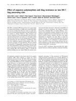
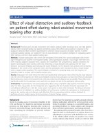
Solid models of the Wagner SL cementless femoral
revision stem were obtained from the manufacturer
(Zimmer GmbH, Winterthur, Switzerland, Figure 1). Two
prosthetic designs were investigated: the standard prosthe-
sis (34 mm offset) and an increased offset design (44 mm
offset). To study the influence of surgical technique, both
stem designs were implanted virtually with 4 or 14 degrees
of anteversion (Figure 1) into a solid model of the Standar-
diz ed Femur following the manufacturers recommen ded
technique. Thereby, the influence of both design and sur-
gical technique on implant stresses was characterized and
compared between four models.
Musculoskeletal analysis
Based on a previously validated musculoskeletal model
of the lower limb [20], muscle and joint contact forces
were deri ved and subsequently applied to the finite ele-
ment models [22]. In brief, the muscle attachment sites
B
A
Figure 1 Prosthes is designs and their implantations .A(top):
Two different designs of the Wagner revision stem. Left: 34 mm
offset prosthesis (standard prosthesis). Centre: 44 mm offset
prosthesis (increased offset prosthesis). Right: Superposition of the
two stem designs, with the standard prosthesis shown as
translucent. B (bottom): Variation of surgical implantation. Left: 44
mm offset stem implanted at 4° (transparent) and 14° of femoral
anteversion, Right: 34 mm offset stem implanted at 4° (transparent)
and 14° of femoral anteversion.
Heller et al. Journal of Orthopaedic Surgery and Research 2011, 6:20
/>Page 2 of 9
and joint coordinates were obtained from the visible
human and t hen scaled to fit the anatomy of t he Stan-
dardized femur (CT-data, Visible Human, NLM, USA).
The muscle paths were modelled as straight lines from
origin to insertion sites, wrapping around the bone to
represent the more realistic curved paths of the muscles.
The physiological cross-sectional area of each muscle
was determined from the literature and sc aled to fit an
assumed body weight of 820N. Inverse dynamics calcu-
lations based on measured forces from gait cycles of a
patient were used to determine intersegmental resultant
forces for the Standardized Femur geometry. Static opti-
misation was performed to minimize sum of the square
of the muscle stresses [24]. A balanced set o f muscle
and joint contact forces was therefore determined and
applied for each finite element model configuration
(Table 1, Table 2).
Finite element models
Meshes for all components in the finite element models
were generated using non-linear second order 10-node
tetrahedral elem ents (Patran, MSC Software Corp, Santa
Ana, CA, USA). Depending on the combination of pros-
thetic design and implantatio n, the developed models
resulted in a total element count of up to 131,300.
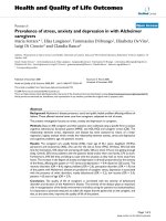
The effect of bone defects was analysed by simulating
the cortical thinning and bone loss conditions under
which the Wagner SL stem might be used clinically. A
total of five bone defects exhibiting different extents of
bone loss were analysed (Figure 2): a proximal defect (type
I, [25]), a proximal medial (type II), a proxima l lateral
(type II), a large bone defect (type IIIa), and an extended
bone defect (type IIIb). The length of the largest defect
(extended defect), starting from the tip of the greater tro-
chanter measured 17.3 cms. In order to facilitate compari-
sons across the different defects, a single implant size
(stem diameter) was used throughout. Here, the determi-
nation of the implant siz e was driven by the mo st
extended defect that was anticipated to represent the
worst case scenario in terms of implant stresses, and for
which the stem size chosen was considered adequate.
In addition to removing the trabecular bone, the thin-
ning of the cortex associated with this form of bone
defect was simulated by reducing the material properties
of specific regions of the cortex (Figure 3) to an elastic
modulusof5GPaandaPoisson’s ratio of 0.4. By using
this reduced modulus but maintaining the intact bone’s
actual thickness, the resulting bending stiffness (second
Table 1 Three-dimensional hip contact force components
[N] during normal walking, as applied to the finite-
element-models for each of the four different
implantation configurations
Implantation Configuration Hip Contact Force Component
xy z
A: 34 mm offset, 4° anteversion -611 -73 -2539
B: 44 mm offset, 4° anteversion -659 -100 -2449
C: 34 mm offset, 14° anteversion -639 -4 -2679
D: 44 mm offset, 14° anteversion -694 -24 -2592
Positive force components act medial (+x), anterior (+y), superior (+z). A, B, C,
D represent the four implant configurations.
Table 2 Muscle forces [N] applied in the finite-element-
analyses for each of the four different implantation
configurations (A to D, compare Table 1)
Muscle Force
Muscle A B C D
Gluteus maximus part 1 202.1 181.8 161.4 139.8
Gluteus maximus part 2 48.1 39.8 37.0 30.2
Gluteus maximus part 3 126.7 163.1 126.1 163.4
Gluteus medius part 1 251.6 241.7 221.9 213.1
Gluteus medius part 2 130.9 136.5 122.7 128.3
Gluteus medius part 3 267.6 294.1 261.2 285.6
Gluteus minimus part 1 19.0 18.9 17.2 17.2
Gluteus minimus part 2 32.8 34.7 31.1 32.9
Gluteus minimus part 3 65.8 75.9 65.6 74.9
Pirirformis 81.9 68.6 64.3 53.6
Biceps femoris caput long. 290.0 370.3 300.5 383.2
Semitendinos us 470.6 496.5 492.1 517.8
Semimembranosus 37.9 40.0 38.8 40.6
Tensor fascia latae 36.2 47.7 38.1 49.2
Gastrocnemius lateralis 7.8 13.2 8.6 13.9
Biceps femoris caput brevis 9.4 14.3 10.0 14.9
Vastus intermedius 442.9 456.3 448.1 460.9
Vastus lateralis 428.0 500.8 439.1 511.3
Vastus medialis 106.1 41.7 100.7 5.4
Cortex defect
(Paprosky classification)
Affected cortex region
proximal (type I) 1,2
proximal-medial (type II) 2,4
proximal-lateral (type II) 1,3
large bone defect (type IIIa)
extended bone defect (type IIIb)
1,2,3,4
1,2,3,4,5
Figure 2 Bone defect regions. In order to assess the effect of
different extents of femoral bone defect on implant loading, the
femoral cortex was divided into a number of regions (medial, lateral,
proximal, distal) according to the Paprosky classification (Paprosky et
al., 1994). The material properties of the cortex were then reduced
to simulate the effects of bone loss for each of the different defect
situations.
Heller et al. Journal of Orthopaedic Surgery and Research 2011, 6:20
/>Page 3 of 9
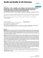
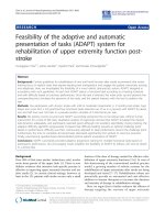
Figure 3 Implant stresses within the standard design prosthesis as a function of the extent of the bone defect. This figures shows the
effect of the extent of bone defect on the tensile stresses within the standard prosthesis (34 mm femoral offset) implanted at 4° of femoral
anteversion. In image A (top), a histogram of the implant stresses is shown. Here, for each bone defect simulation implant elements were
grouped according to their maximum principle (i.e. tensile) stress (denoted by the symbol s) and are presented as a percentage of the total
number of elements in the implant. Image B (bottom) shows the stress distribution along the lateral aspect of the implant for bone defects of
increasing extent.
Heller et al. Journal of Orthopaedic Surgery and Research 2011, 6:20
/>Page 4 of 9
moment of area) in the coronal plane of the cortex was
calculated to be equivalent to a 2 mm thin cortex with an
elastic modulus of 17 GPa. The intact cortices of the bone
(distal sections of the femur) were assigned an elastic
modulus of 17 GPa (ν = 0.4 ) [26], while trabecular bone
was modelled with an elastic modulus of 2 GPa (ν = 0.4).
The titanium alloy Wagner SL revision stem was assigned
an elastic modulus of 110 GPa, and a Poisson’sratioof0.3.
Tied contact constraints were used over the distal
anchorage, while the remaining contact surface areas of
the prosthesis and bone interface were defined as fric-
tionless sliding, using a modified formulation for the
non-linear second order tetrahedrons. Nodes on the
slave contact surface were initially adjusted to lie
directly on the master surface without inducing any
stresses or strains within either material.
To prevent rigid body motion, displacement con-
straints were applied to nodes at the centre of the knee,
the location of the hip contact force and on the distal
lateral surface of the lateral condyle [27]. Thus, three
translational degrees of freedom were constrained at the
knee; the hip was allowed to translate along the axis
connecting the hip and knee; the node on the lateral
condyle was constrained to prevent rotation of the
model about the hip-knee axis.
Non-linear finite element analysis was performed using
ABAQUS v6.5 (ABAQUS Inc., Providence, USA). Implant
stresses were evaluated by querying the element centroids
and grouped into element sets that corresponded to cer-
tain stress limits. The different bone defect models were
then compared to determine the influence of offset and
anteversion modifications on implant stresses.
Results
For the 34 mm offset ste m implanted a t 4° of femoral
anteversion, more than 88% of the implant model
experienced tensile stresses that remained below 50MPa
(Figure 3 A). The maximum tensile stress calculated
withinasingleelementoftheimplantforthecaseofa
proximal (type I) defect was 141MPa.
Influence of the extent of bone defect
In general, the implant stresses increased with progres-
sing bone defect severity (Figure 3): while only 5% of
the implant experienced stresses over 50MPa for a type
I defect, over 12 % of the i mplant was subjected to these
stresses for the reconstruction of a type IIIb defect. For
this extended type IIIb bone defect, peak stresses within
the standard prosthesis (34 mm offset) increased by 59%
when compared to the implant stresses for the proximal
(type I) defec t. The largest maximum princ ipal (i.e. ten-
sile) stresses were distributed along the lateral aspect of
the shaft, and distal lateral side of the implant neck
(Figure 3). When comparing proximal bone defects,
bone loss on the medial side had a larger effect on the
implant stresses than bone loss on the lateral side.
Influence of prosthesis design
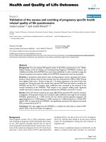
Increasing the neck length from 34 to 44 mm induced
larger impla nt stresses (Figure 4). For situations with an
Figure 4 Effect of design variation on the stress distribution in the implants . For the situation of an extended bone defect (Paprosky type
IIb) this figure demonstrates the effect of femoral offset on the maximum principle (i.e. tensile) stresses within the implant. The implant
elements were grouped according to their stress (denoted by the symbol s) level. This data is presented as a histogram in image A (top), where
the data are reported as a percentage of the total number of elements in the implant. Below, image B compares the stress distributions along
the lateral aspect of the implant for a type IIIb defect for the two different offsets. It can be seen that the implant with the increased offset
experiences larger tensile stresses.
Heller et al. Journal of Orthopaedic Surgery and Research 2011, 6:20
/>Page 5 of 9
extended bone defect (type IIIb), together with an
increased offset (44 mm) prosthesis implanted at
4° femoral anteversion, more than 26% of the implant
experienced tensile stresses of over 50MPa, while only
12% of the implant was subjected to such stresses for
the standard offset. In this s cenario, an upper stress
limit of 225MPa was determined, which amounted to a
16.7% increase in peak tensile stresses in co mparison to
thesamedefectsituationfor the standard prosthesis.
The stresses for the increased offset design appeared to
be distributed further on the lateral aspect and distal
neck of the implant.
Influence of anteversion
Increasing the anteversion from 4° to 14° in the standard
prosthesis (34 mm) resulted in an increase o f approxi-
mately 5% in peak tensile stresses within the implant
(Figure 5). However, implantation of the stem wit h an
anteversion of 14°, together with a combined increase in
offset (44 mm) caused almost a 15% increase in stresses
within the implant when compared to the standard
prosthesis (Figure 5).
Discussion
By examining the effects of two different implant offsets
and the variation of anteversion, this numerical analysis
demonstrates that the stress leve ls developed within the
Wagner SL revision stem are the highest in situations
with severely compromised bone stock. A combination
of increased offset and anteversion, resulted in the high-
est stresses, but even this combination should not
induce critical stresses in the implant during normal
activities of daily living, even for an extensive bone
defect (Paprosky type IIIb), necessitating distal fixation.
In all regions of the implant, the maximum determined
stresses of 225MPa remained well below the implant
material’s fatigue limit of 450MPa [28], suggesting that
the implant is capable of withstanding normal physiolo-
gical loading without the risk of failure.
While in clinical practic e the diameter of the stem to
be implanted would likely be influenced also by the
extent of the bone defect, in the current study a single
stem diameter was used for all defects in order to facil i-
tate comparison s across the diff erent defect conditions.
As the selection of the implant size was driven by the
worst case scenario, the current model is likely to over-
estimate the amount of unloading of the remaining
bone stock (stress shielding) for the less critical defect
conditions. F urther analyses should thus aim to better
quantify the influence of stem size on the stress shield-
ing in the remaining bone stock. For such analyses that
investigate the mechanical environment of the bone in
Figure 5 Effect of surgical technique on the stress distribution within the implants. For the situation of an extended bone defect
(Paprosky type IIb) we further explored the effect of surgical technique (implantation) on the implant stresses by varying femoral anteversion
and examining its effect on the maximum principle (i.e. tensile) implant stresses. Here, the implant stresses of the standard (34 mm) and
increased offset (44 mm) prostheses implanted at 14° of femoral anteversion are compared. This data is again presented as a histogram in image
A (top), with the results reported as a percentage of the total number of elements in the implant stressed within a certain stress level. Below,
image B compares the stress distributions along the lateral aspect of the implant for a type IIIb defect for the two different offsets. It can be
seen that also for 14° of femoral anteversion the implant with the increased offset experiences larger tensile stresses than the standard
prosthesis.
Heller et al. Journal of Orthopaedic Surgery and Research 2011, 6:20
/>Page 6 of 9
more detail, however, a more detailed geometrical model
of the defect situation would be required.
Although it has been debated that bone support of the
proximal part of a revision implant is not necessary
[29], concerns about the stresses generated in the
implant still exist. To overcome the influences of
extended bone defects on implant stresses in the revi-
sion stem, distal fixation [13], fluted stems [30], material
properties [31], appropriate reconstruction of offset and
anteversion have been recommended. The study results
supports evidence on the influence of proximal bone
support on implant stresses, particularly on the tension
side of the implant [32]. The results suggest that key to
restorable joint function and to avoid critical implant
stresses is to provide distal fixation of the implant dur-
ing extended bone d efect conditions. The simulation
results also support clinical evidence of the increased
implant survival observed during distal fixation of the
implant during revision THR [13,30]. Assessing the con-
ditions in the implant under extreme loading, during
uncoordinated activities such as stumbling, when hip
contact forces can reach over 8 times body weight [ 33],
was beyond the scope o f this study, however, and may
pose more of a challenge for the survival of the implant.
Although, to the best of our knowledge, there is no lit-
erature on the cortex thickness for the range of defect
situations examined in this study, we have modelled a
2 mm thin proximal cortex (based on radiographic obser-
vations), by using an equivalent elasti c modulus of 5GPa,
as confirmed using second moment of area calculations.
As a result, the implant stresses calculated using physiolo-
gical-like loading conditions on the revision prosthesis
show no critical stresses that are likely to lead to implant
failure. This supports the low rates of fracture reported in
clinical studies for the standard Wagner SL stem used in
these challenging revision situations [5,9].
The use of an implant with an increased offset is
thought to improve the stability of the joint by removing
any laxity of the surrounding soft tissues. Changes in the
geometry of the reconstructed joint, however, are known
to influence the joint contact forces and therefore the
implant stresses [19,22,34]. By effectively increasing the
lever arm of the one-joint abductor muscles at the hip,
the larger offset prosthe sis reduces the muscle forces
required to balance the varus moment at the hip, and
consequently the hip joint contact forces [22]; findings
that are in agreement with a simplified experimental
study [35]. Despite this likely decrease in the muscle
and hip joint contact forces, the present work indicates
that in creasing the offset can lead to an in crease in the
implant stresses. From a mechanical perspective, it
seems that the influence of the decrease in muscle and
joint contact forces, is outweighed by the increased lever
arm of the hip joint contact force itself, which is created
from a combination of the increased implant offset and
the distal anchorage, and actually results in larger bend-
ing and torsional forces on the implant. While slight
modifications in the neck region of the implant had to
be intro duced to increase the prosthesis offset the stem
was entirely iden tical between the two impl ant variants,
facilitating the comparison of the stresses within the
implant s haft between the two designs. The implemen-
tation of geometrical modifications to a clinically suc-
cessful implant therefore raises the questio n of whether
the b enefits of tight soft tissues encapsulating the joint,
andthereforeapossibleimprovement in joint function
and reduction in the dislocation rate, outweigh the
increased risks of implant failure when implanted in a
mechanically incompetent femur.
The maximum implant stresses in this study were
observed when the increased offset (44 mm) version of
the stem was implanted with an anteversion of 4°. Simi-
lar stress magnitudes were produced by the configura-
tion of a n increased offset and increased anteversion.
Whilst a direct validation of the predicted stresses
against e.g. in vitro measured conditions would be desir-
able, current in vitro designs do not allow to represent
the complex musculoskeletal loading conditio ns as used
in the current study. In order to ensur e that the com-
parisons of the predicted implant stresses were valid, a
convergence analysis in which the element sizing was
increased over a number refinements and also the order
of the shape function of the elements was varied from
linear to non-linear functions, it was ensured that the
element sizes were adequate to represent the stress
fields within the implanted femurs. Furthermore, we
could show that by applying physiological-like boundary
conditions (i.e. muscle and joint contact forces as well
as physiologically rea sonable displacement constraints
[27]), the overall deformation of the bone-implant con-
structs fell within 1 to 2 mm and therefore within the
range of experimentally measured data. Lastly, as largely
identical meshes of the shaft region of the implants
were used in this comparative study design, any sys-
tematic error in the modeling process would likely influ-
ence the results for all models in a similar manner and
would therefore unlikely influence the comparisons.
Since the geometry of the Standardized Femur was
used in this study, the loading conditions could onl y be
estimated. However, the methodology has been pre-
viously validated against measured in vivo hip contact
forces in patients [20] and resulted in a complete and
balance d set of muscle and joint cont act forces. The use
of such a balanced force model, together with physiolo-
gical b oundary conditions [27], is essenti al for analysing
loading conditions in the femur [21].
This study has evaluated the stresses in the Wagner
revision stem after variations in design (offset) and
Heller et al. Journal of Orthopaedic Surgery and Research 2011, 6:20
/>Page 7 of 9
surgical implantation (anteversion), and establishes an
initial understanding of the possible risks that could
accompany a modification to the offset of a distally
anchored revision stem and variations in its surgical
implantation. By considering the extreme case of a type
IIIb bone defect, we conclude that when the Wagner
stem is used within its prescribed manufacturer’s limit
the restoration of femoral offset to restore joint function
is unlikely to result in stresses that lead to mechanical
failure of the implant during routine activities of daily
living. These results will need to be confirmed clinically,
especially in cases w here uncoordinated activities such
as stumbling are prevalent.
Acknowledgements
This study was partially supported by a grant from Zimmer GmbH
(Winterthur, Switzerland), and the German Research Foundation (DFG SFB
760). The authors would like to thank Dr. Jean-Pierre Kassi for his support in
the early stages of the project. The solid model of the Standardized Femur
was created by Marco Viceconti; it is openly available on the Internet at the
ISB Finite Element Repository managed by the Istituti Ortopedici Rizzoli,
Bologna, Italy.
Authors’ contributions
MOH co-conceived and participated in the coordination of the study as well as
drafting the manuscript. MM performed all finite element analyses of the
implanted femur and aided in drafting the manuscript. WRT aided in study
conception, provided the musculoskeletal loading conditions and participated
in the manuscript preparation. DYK created the solid models and performed
first pilot studies to create the finite element meshes, including collection of
pilot data and initial analyses into the straining of the intact bone. AS
participated in the transfer and application of the musculoskeletal loading
conditions onto the finite element models and performed initial analyses of the
implanted femur. GND conceived the study and participated in its coordination.
CP co-conceived the study, supervised the clinical determination of implant
sizing and the implantation of the prosthesis as well as the definition of the
defects. He also aided in drafting and approving the manuscript. All authors
read and approved the final manuscript.
Competing interests
The authors declare that they have no competing interests.
Received: 16 July 2010 Accepted: 13 May 2011 Published: 13 May 2011
References
1. Sporer S, Paprosky W: Revision total hip arthroplasty: the limits of fully
coated stems. Clin Orthop Relat Res 2003, 203-209.
2. Morrey BF, Kavanagh BF: Complications with revision of the femoral
component of total hip arthroplasty: Comparison between cemented
and uncemented techniques. Journal of Arthroplasty 1992, 7:71-79.
3. Mulroy W, Harris W: Revision total hip arthroplasty with use of so-called
second-generation cementing techniques for aseptic loosening of the
femoral component. A fifteen-year-average follow-up study. J Bone Joint
Surg Am 1996, 78:325-330.
4. Wagner H, Wagner M: Conus hip prosthesis. Acta Chir Orthop Traumatol
Cech 2001, 68:213-221.
5. Böhm P, Bischel O: Femoral revision with the Wagner SL revision stem:
Evaluation of one hundred and twenty-nine revisions followed for a
mean of 4.8 years. J Bone Joint Surg Am 2001, 83:1023-1031.
6. Mantelos G, Koulouvaris P, Kotsovolos H, Xenakis T: Consistent new bone
formation in 95 revisions: average 9-year follow-up. Orthopedics 2008,
31:654.
7. Gutierrez Del Alamo J, Garcia-Cimbrelo E, Castellanos V, Gil-Garay E:
Radiographic bone regeneration and clinical outcome with the Wagner
SL revision stem: a 5-year to 12-year follow-up study. J Arthroplasty 2007,
22:515-524.
8. Isacson J, Stark A, Wallensten R: The Wagner revision prosthesis
consistently restores femoral bone structure. International Orthopaedics
2000, 24:139-142.
9. Han CD, Yang IW, Park J: Femoral Revision with the Wagner SL Revision
Stem. J Korean Orthop Assoc 2007, 42:241-248.
10. Kolstad K, Adalberth G, Mallmin H, Milbrink J, Sahlstedt B: The Wagner
revision stem for severe osteolysis. 31 hips followed for 1.5-5 years. Acta
Orthop Scand 1996, 67:541-544.
11. Hodge WA, Andriacchi TP, Galante JO: A relationship between stem
orientation and function following total hip arthroplasty. J Arthroplasty
1991, 6:229-235.
12. Cheal EJ, Spector M, Hayes WC: Role of loads and prosthesis material
properties on the mechanics of the proximal femur after total hip
arthroplasty. J Orthop Res 1992, 10:405-422.
13. Ovesen O, Emmeluth C, Hofbauer C, Overgaard S: Revision Total Hip
Arthroplasty Using a Modular Tapered Stem With Distal Fixation: Good
Short-Term Results in 125 Revisions. J Arthroplasty 2010, 25:348-354.
14. Regis D, Sandri A, Bartolozzi P: Stem modularity alone is not effective in
reducing dislocation rate in hip revision surgery. J Orthop Traumatol
2009, 10:167-171.
15. Bader R, Barbano R, Mittelmeier W:
Treatment of recurrent dislocation
associated
with impingement after revision total hip arthroplasty. Acta
Orthop Belg 2005, 71:98-101.
16. Charles MN, Bourne RB, Davey JR, Greenwald AS, Morrey BF, Rorabeck CH:
Soft-tissue balancing of the hip: the role of femoral offset restoration.
Instr Course Lect 2005, 54:131-141.
17. Crowninshield R, Maloney W, Wentz D, Levine D: The role of proximal
femoral support in stress development within hip prostheses. Clin
Orthop Relat Res 2004, 176-180.
18. Dorr LD, Wan Z: Causes of and treatment protocol for instability of total
hip replacement. Clin Orthop Relat Res 1998, 144-151.
19. Heller MO, Bergmann G, Deuretzbacher G, Claes L, Haas NP, Duda GN:
Influence of femoral anteversion on proximal femoral loading:
measurement and simulation in four patients. Clin Biomech 2001,
16:644-649.
20. Heller MO, Bergmann G, Deuretzbacher G, Dürselen L, Pohl M, Claes L,
Haas NP, Duda GN: Musculo-skeletal loading conditions at the hip during
walking and stair climbing. J Biomech 2001, 34:883-893.
21. Duda GN, Heller M, Albinger J, Schulz O, Schneider E, Claes L: Influence of
muscle forces on femoral strain distribution. J Biomech 1998, 31:841-846.
22. Kleemann RU, Heller MO, Stoeckle U, Taylor WR, Duda GN: THA loading
arising from increased femoral anteversion and offset may lead to
critical cement stresses. Journal of Orthopaedic Research 2003, 21:767-774.
23. Bougherara H, Zdero R, Shah S, Miric M, Papini M, Zalzal P, Schemitsch E: A
biomechanical assessment of modular and monoblock revision hip
implants using FE analysis and strain gage measurements. Journal of
Orthop Surg and Res 2010, 5:34.
24. Taylor WR, Heller MO, Bergmann G, Duda GN: Tibio-femoral loading
during human gait and stair climbing. J Orthop Res 2004, 22:625-632.
25. Paprosky WG, Bradford MS, Younger TI: Classification of bone defects in
failed prostheses. Chir Organi Mov 1994, 79:285-291.
26. Reilly DTBA, Frankel VH: The elastic modulus for bone. J Biomech Eng
1974, 7:271-275.
27. Speirs AD, Heller MO, Duda GN, Taylor WR: Physiologically based
boundary conditions in finite element modelling. J Biomech 2006,
40:2318-2323.
28. Windler M, Klabunde R: Titanium for Medical Applications; Titanium in
Medicine; Part V - Medical Applications. Springer Verlag 2001.
29. Murphy SB, Rodriguez J: Revision total hip arthroplasty with proximal
bone loss. J Arthroplasty 2004, 19:115-119.
30. Buttaro MA, Mayor MB, Van Citters D, Piccaluga F: Fatigue fracture of a
proximally modular, distally tapered fluted implant with diaphyseal
fixation. J
Arthroplasty 2007, 22:780-783.
31. Garbuz DS, Toms A, Masri BA, Duncan CP: Improved outcome in femoral
revision arthroplasty with tapered fluted modular titanium stems. Clin
Orthop Relat Res 2006, 453:199-202.
32. Woolson ST, Milbauer JP, Bobyn JD, Yue S, Maloney WJ: Fatigue Fracture
of a Forged Cobalt-Chromium-Molybdenum Femoral Component
Heller et al. Journal of Orthopaedic Surgery and Research 2011, 6:20
/>Page 8 of 9
Inserted with Cement. A Report of Ten Cases. J Bone Joint Surg Am 1997,
79:1842-1848.
33. Bergmann G, Graichen F, Rohlmann A: Hip joint contact forces during
stumbling. Langenbecks Arch Surg 2004, 389 :53-59.
34. Steinberg B, Harris W: The “Offset” Problem in Total Hip Artroplasty.
Contemporary Orthopaedics 1992, 24:556-562.
35. Davey JR, O’Connor DO, Burke DW, Harris WH: Femoral component offset.
Its effect on strain in bone-cement. J Arthroplasty 1993, 8:23-26.
doi:10.1186/1749-799X-6-20
Cite this article as: Heller et al.: Influence of prosthesis design and
implantation technique on implant stresses after cementless revision
THR. Journal of Orthopaedic Surgery and Research 2011 6:20.
Submit your next manuscript to BioMed Central
and take full advantage of:
• Convenient online submission
• Thorough peer review
• No space constraints or color figure charges
• Immediate publication on acceptance
• Inclusion in PubMed, CAS, Scopus and Google Scholar
• Research which is freely available for redistribution
Submit your manuscript at
www.biomedcentral.com/submit
Heller et al. Journal of Orthopaedic Surgery and Research 2011, 6:20
/>Page 9 of 9