Advances in Measurement Systems Part 12 pptx
Bạn đang xem bản rút gọn của tài liệu. Xem và tải ngay bản đầy đủ của tài liệu tại đây (4.88 MB, 40 trang )
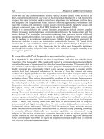
Fig. 21. Ratio response of the system at different polarization states
Fig. 22. Experimental arragement to study the impact of PDL on wavelength measurements
Estimation of the maximum variation in the measured wavelength is important as we can
determine the system’s worst case performance. The maximum and minimum values of the
fluctuation of PDL of the filter arm due to the 3 dB coupler and the fiber filter can be
calculated using Equation (14). A comparison of the estimated maximum and minimum of
the PDL of the filter arm with the measured PDL of the filter arm is shown in Fig. 23.
Fig. 23. Maximum and minimum PDL of the fiber filter arm and its comparison with the
measured PDL.
For a ratiometric system both of the arms contribute to the total ratio variation. The PDL of
the reference arm and filter arm obtained from the experiment provides the maximum and
minimum power levels of each arm. Based on that, a numerical simulation can be carried
out to find the maximum ratio variation and can be estimated using Equation (15). The
estimated variation in ratio and wavelength of the system and its comparison with the
measured versions are shown in Fig. 24(a) and Fig. 24(b) respectively. To estimate the
wavelength error, the local slope of the ratio spectrum is used. The wavelength error, which
is a consequence of ratio variation, in practice depends on the slope of the system which is
low at shorter wavelengths and high at longer wavelengths which results in a larger error at
shorter wavelengths than at longer wavelengths. In the example shown in Fig. 24 for a fiber
filter of 10.5 mm radius and 15 turns it is estimated that the maximum wavelength error at
1500 nm is 1.9 nm from the original value. Any measured error in wavelength should be
within this estimated wavelength error range.
From the figure it is clear that the measured ratio and wavelength variation of the system are
well within the estimated limits. The effect of fluctuation in the attenuation due to PDL, which
leads to the variation in ratio and measured wavelength, is confirmed by the results.
(a) (b)
Fig. 24. Comparison of measured error with the estimated maximum error because of PDL
(a) ratio error (b) wavelength error.
Without predicting the wavelength error due to PDL of the components used in the system,
characterizing a system to a wavelength resolution or accuracy such as 0.01 nm is
meaningless. Thus to determining the accuracy and resolution of the system, it is essential
that the PDL and its effects on the system are quantified.
6. Polarization dependent loss minimization techniques
In the case of macro-bend fiber filter since the PDL of the filter originates from the difference in
bend loss for TE and TM modes one method to compensate the bend loss of the modes is to
split the fiber filter into two bending sections with equal length and introduce a 90
0
twist in the
middle of the filter between the two sections (Rajan et al., 2008). This changes the polarization
state for the second bending section, i.e., the TE (TM) mode is turned to be the TM (TE) mode
PassiveAll-FiberWavelengthMeasurementSystems:PerformanceDeterminationFactors 437
Fig. 21. Ratio response of the system at different polarization states
Fig. 22. Experimental arragement to study the impact of PDL on wavelength measurements
Estimation of the maximum variation in the measured wavelength is important as we can
determine the system’s worst case performance. The maximum and minimum values of the
fluctuation of PDL of the filter arm due to the 3 dB coupler and the fiber filter can be
calculated using Equation (14). A comparison of the estimated maximum and minimum of
the PDL of the filter arm with the measured PDL of the filter arm is shown in Fig. 23.
Fig. 23. Maximum and minimum PDL of the fiber filter arm and its comparison with the
measured PDL.
For a ratiometric system both of the arms contribute to the total ratio variation. The PDL of
the reference arm and filter arm obtained from the experiment provides the maximum and
minimum power levels of each arm. Based on that, a numerical simulation can be carried
out to find the maximum ratio variation and can be estimated using Equation (15). The
estimated variation in ratio and wavelength of the system and its comparison with the
measured versions are shown in Fig. 24(a) and Fig. 24(b) respectively. To estimate the
wavelength error, the local slope of the ratio spectrum is used. The wavelength error, which
is a consequence of ratio variation, in practice depends on the slope of the system which is
low at shorter wavelengths and high at longer wavelengths which results in a larger error at
shorter wavelengths than at longer wavelengths. In the example shown in Fig. 24 for a fiber
filter of 10.5 mm radius and 15 turns it is estimated that the maximum wavelength error at
1500 nm is 1.9 nm from the original value. Any measured error in wavelength should be
within this estimated wavelength error range.
From the figure it is clear that the measured ratio and wavelength variation of the system are
well within the estimated limits. The effect of fluctuation in the attenuation due to PDL, which
leads to the variation in ratio and measured wavelength, is confirmed by the results.
(a) (b)
Fig. 24. Comparison of measured error with the estimated maximum error because of PDL
(a) ratio error (b) wavelength error.
Without predicting the wavelength error due to PDL of the components used in the system,
characterizing a system to a wavelength resolution or accuracy such as 0.01 nm is
meaningless. Thus to determining the accuracy and resolution of the system, it is essential
that the PDL and its effects on the system are quantified.
6. Polarization dependent loss minimization techniques
In the case of macro-bend fiber filter since the PDL of the filter originates from the difference in
bend loss for TE and TM modes one method to compensate the bend loss of the modes is to
split the fiber filter into two bending sections with equal length and introduce a 90
0
twist in the
middle of the filter between the two sections (Rajan et al., 2008). This changes the polarization
state for the second bending section, i.e., the TE (TM) mode is turned to be the TM (TE) mode
for the second bending section. The net effect is that the individual losses for the input TE and
TM modes are equalized over the total length of the fiber so that the PDL can be minimized for
the whole bending section. The schematic of the configuration is shown in Fig. 25.
To demonstrate how the 90
0
twist reduces the PDL at higher bend lengths, the PDL of the
filter is measured for different bend lengths and is shown in Fig. 26(a). For comparison the
PDL of fiber filters without a twist is also presented for the same number of turns. From the
figure it is clear that PDL is not eliminated completely in the fiber filter due to physical
inaccuracies such as small variations in the bend length of the two sections of the filter and
variations in the twist angle from 90
0
leading to residual PDL. It should be noted that a twist
in the fiber induces circular birefringence and can make the fiber polarization dependent.
However, such stress induced birefringence is very low in SMF28 fiber which means that the
twist induced birefringence is negligible and its contribution to the PDL of the fiber filter is
very small. Overall from the figures it is clear that the PDL of the fiber filter decreases
considerably with a 90
0
twist at higher bend lengths which in turn allows the filter to utilize
a larger number of turns to obtain the required steepness and thus increase the
measurement resolution of the system without reaching an unacceptable level of PDL.
The PDL of an SMS structure can be reduced/eliminated by using accurate splicing
methods which reduce the lateral offset between the SMF and the MMF at both ends.
However conventional fusion splicers cannot guarantee a perfect splicing without lateral
offset. In such cases by introducing a rotational offset of 90
0
will minimize the PDL as shown
in Fig. 20. This is because at a rotational core offset of 90
0
, the orientation between the
input/output SMF and the input field direction of TE/TM are parallelized. Thus the overlap
between the field profile at the output end of the MMF section and the eigen-mode profile of
the output SMF for both TE and TM modes are similar and thus the PDL will be minimised.
Minimizing the polarization dependency of the fiber filter alone will not minimize the
polarization dependency of the whole system. As the system contains another PDL
component, the 3 dB coupler, it is important to minimize the PDL of the coupler also. One
way to minimize the total polarization dependency of the system is using a polarization
insensitive (PI) 3 dB couplers (couplers with very low PDL, in the range of 0.01 - 0.02 dB).
The wavelength inaccuracy of a macro-bend fiber filter together with low PI 3 dB coupler
and its comparison with conventional system are shown in Fig. 26(b). Thus, for wavelength
measurements based on macro-bend fiber filters the polarization dependency can be
significantly reduced by the 90
0
twisted fiber filter together with low PI 3 dB coupler
Fig. 25. Bending configurations of the macro-bend fiber filter: conventional bending and a
90
0
twist between the bending sections.
configuration and can deliver measurements with high wavelength accuracy irrespective of
the input state of polarization.
(a) (b)
Fig. 26. (a) PDL of the fiber filters with 90
0
twist and its comparison with the PDL of the
filters without twist (b) Comparison of wavelength errors in a low polarization system vs.
conventional system
7. Temperature induced inaccuracies in a macro-bend fiber filter based WMS
When a single-mode fiber forms a macro-bend, WGMs may be created, which propagate in
the cladding or buffer. These WGMs can interfere with the guided core mode to produce
interference induced oscillations in the bend loss spectral response (Morgan et al., 1990). The
dominant source of WGMs is the buffer-air interface and also the cladding-buffer interface.
The formation of such whispering gallery modes effectively creates an interferometer within
the fiber, with the core and buffer/cladding as the two arms. To utilize a macro-bend fiber
as an edge filter, an absorption layer is applied to the buffer coating to eliminate these WG
modes, which makes the bend loss spectral response smoother and ideally achieves a linear
response versus wavelength as explained earlier.
The temperature sensitivity of such a fiber filter arises mainly from the temperature
sensitive properties of the buffer coating, characterized by the thermo-optic coefficient
(TOC) and thermal expansion coefficient (TEC). The TOC and TEC of the buffer coatings,
such as acrylates, are much higher than those of fused silica which forms the core and the
cladding of the fiber. Macro-bend fiber edge filters can be based on low bend loss fiber such
as SMF28 fiber or high bend loss fiber such as 1060XP as explained in section 2.
The most common single-mode fiber, SMF28 fiber, has two buffer coating layers. Due to the
coating layers, even with the absorption layer a low level of reflection from the cladding-
primary coating boundary will still exist and interfere with the core mode. As a result of this
when there is a change in temperature which changes the refractive index and thickness of
the buffer coating, the path length variation of the WG modes and phase difference between
the WG mode and the core mode leads to constructive and destructive interference between
the WG mode and the core mode. This results in oscillatory variations in the spectral
response of the bend loss. In a macro-bend fiber filter without a buffer coating but with an
PassiveAll-FiberWavelengthMeasurementSystems:PerformanceDeterminationFactors 439
for the second bending section. The net effect is that the individual losses for the input TE and
TM modes are equalized over the total length of the fiber so that the PDL can be minimized for
the whole bending section. The schematic of the configuration is shown in Fig. 25.
To demonstrate how the 90
0
twist reduces the PDL at higher bend lengths, the PDL of the
filter is measured for different bend lengths and is shown in Fig. 26(a). For comparison the
PDL of fiber filters without a twist is also presented for the same number of turns. From the
figure it is clear that PDL is not eliminated completely in the fiber filter due to physical
inaccuracies such as small variations in the bend length of the two sections of the filter and
variations in the twist angle from 90
0
leading to residual PDL. It should be noted that a twist
in the fiber induces circular birefringence and can make the fiber polarization dependent.
However, such stress induced birefringence is very low in SMF28 fiber which means that the
twist induced birefringence is negligible and its contribution to the PDL of the fiber filter is
very small. Overall from the figures it is clear that the PDL of the fiber filter decreases
considerably with a 90
0
twist at higher bend lengths which in turn allows the filter to utilize
a larger number of turns to obtain the required steepness and thus increase the
measurement resolution of the system without reaching an unacceptable level of PDL.
The PDL of an SMS structure can be reduced/eliminated by using accurate splicing
methods which reduce the lateral offset between the SMF and the MMF at both ends.
However conventional fusion splicers cannot guarantee a perfect splicing without lateral
offset. In such cases by introducing a rotational offset of 90
0
will minimize the PDL as shown
in Fig. 20. This is because at a rotational core offset of 90
0
, the orientation between the
input/output SMF and the input field direction of TE/TM are parallelized. Thus the overlap
between the field profile at the output end of the MMF section and the eigen-mode profile of
the output SMF for both TE and TM modes are similar and thus the PDL will be minimised.
Minimizing the polarization dependency of the fiber filter alone will not minimize the
polarization dependency of the whole system. As the system contains another PDL
component, the 3 dB coupler, it is important to minimize the PDL of the coupler also. One
way to minimize the total polarization dependency of the system is using a polarization
insensitive (PI) 3 dB couplers (couplers with very low PDL, in the range of 0.01 - 0.02 dB).
The wavelength inaccuracy of a macro-bend fiber filter together with low PI 3 dB coupler
and its comparison with conventional system are shown in Fig. 26(b). Thus, for wavelength
measurements based on macro-bend fiber filters the polarization dependency can be
significantly reduced by the 90
0
twisted fiber filter together with low PI 3 dB coupler
Fig. 25. Bending configurations of the macro-bend fiber filter: conventional bending and a
90
0
twist between the bending sections.
configuration and can deliver measurements with high wavelength accuracy irrespective of
the input state of polarization.
(a) (b)
Fig. 26. (a) PDL of the fiber filters with 90
0
twist and its comparison with the PDL of the
filters without twist (b) Comparison of wavelength errors in a low polarization system vs.
conventional system
7. Temperature induced inaccuracies in a macro-bend fiber filter based WMS
When a single-mode fiber forms a macro-bend, WGMs may be created, which propagate in
the cladding or buffer. These WGMs can interfere with the guided core mode to produce
interference induced oscillations in the bend loss spectral response (Morgan et al., 1990). The
dominant source of WGMs is the buffer-air interface and also the cladding-buffer interface.
The formation of such whispering gallery modes effectively creates an interferometer within
the fiber, with the core and buffer/cladding as the two arms. To utilize a macro-bend fiber
as an edge filter, an absorption layer is applied to the buffer coating to eliminate these WG
modes, which makes the bend loss spectral response smoother and ideally achieves a linear
response versus wavelength as explained earlier.
The temperature sensitivity of such a fiber filter arises mainly from the temperature
sensitive properties of the buffer coating, characterized by the thermo-optic coefficient
(TOC) and thermal expansion coefficient (TEC). The TOC and TEC of the buffer coatings,
such as acrylates, are much higher than those of fused silica which forms the core and the
cladding of the fiber. Macro-bend fiber edge filters can be based on low bend loss fiber such
as SMF28 fiber or high bend loss fiber such as 1060XP as explained in section 2.
The most common single-mode fiber, SMF28 fiber, has two buffer coating layers. Due to the
coating layers, even with the absorption layer a low level of reflection from the cladding-
primary coating boundary will still exist and interfere with the core mode. As a result of this
when there is a change in temperature which changes the refractive index and thickness of
the buffer coating, the path length variation of the WG modes and phase difference between
the WG mode and the core mode leads to constructive and destructive interference between
the WG mode and the core mode. This results in oscillatory variations in the spectral
response of the bend loss. In a macro-bend fiber filter without a buffer coating but with an
applied absorption layer the temperature induced periodic variations in the bend loss can be
eliminated.
A fiber filter based on SMF28 fiber requires multiple bend turns with small bend radii to
achieve a better slope and high wavelength resolution. The removal of the buffer coating
over a meter or more of fiber is beyond practical limits as the fiber breaks if it is wrapped for
more than one turn at small bend radii without a buffer. However, a fiber such as 1060XP is
highly sensitive to bend effects due its low normalized frequency (V). The V parameter for
1060XP fiber is 1.5035 while for SMF28 fiber it is 2.1611. Since the normalized frequency of
the 1060XP is smaller, power will be less confined in the core and will be more susceptible to
bending loss and the bend loss will be higher when compared to SMF28. As a result an edge
filter based on a bend sensitive 1060XP fiber requires only one bend turn and hence the
buffer can be stripped easily and an absorption layer can be applied directly to the cladding.
After removing the buffer coating from the sensor head, the only negative TOC material is
eliminated and the sensor head consists of only positive TOC materials; the cladding and
core, which are made of silica. For the silica core and cladding the thermally induced
effective change in refractive index is linear in nature, resulting in a linear variation of bend
loss with temperature. Since the temperature dependent loss is proportional to the bend loss
in the fiber filter, 1060XP fiber shows higher temperature induced loss, when compared to
its SMF28 counterpart, for the case of a single bend turn. For a system with this
configuration, a temperature corrected calibration is feasible. A temperature corrected
calibration means that temperature of the fiber filter is continually measured and therefore,
the measurement system can apply correction factors to the calibration in use. This allows
the system to be used over a wide range of ambient temperatures (Rajan et al., 2009).
(a) (b)
Fig. 27. Temperature induced wavelength error (a) SMF28 fiber filter (b) 1060XP fiber filter
A comparison of wavelength errors due to ambient temperature variation in the case of edge
filters fabricated from standard singlemode fiber (SMF28) and bend sensitive fiber (1060XP)
are shown in Fig. 27(a) and Fig. 27(b) respectively. While it is apparent that the SMF28 fiber
filter based system is less temperature sensitive, nevertheless the oscillatory nature of the bend
loss and ratio of the system makes correction of the calibrated response unfeasible. For the
SMF28 based filter the only option is to use active temperature stabilization of the filter
temperature. Whereas for the bend sensitive fiber based filter temperature compensation
requires a sensor and compact electronics only, temperature stabilization will additionally
demand a Peltier cooler, heat sinks, a complex feedback control system and, depending on the
ambient temperature variation to be dealt with, will involve significantly higher power
consumption by the system.
The temperature stabilization approach will thus require more physical space, as well as
higher complexity and cost than the temperature compensation approach. Using high bend
loss fibers such as 1060XP will mean that the fiber filter will have higher temperature
dependence than the SMF28 fiber filter, but due to the linear nature of the ratio variation
with temperature, the temperature induced error can be compensated by adding correction
factors to the calibration ratio response. The wavelength accuracy can be improved by
obtaining the correction in the ratio response with smaller temperature intervals or by
extrapolating the correction response between the required temperature intervals. Thus,
irrespective of the temperature dependence of the 1060XP fiber filter, such a filter can be
operated over a wide temperature range, if the correction in ratio response is added to the
original ratio response and thus precise wavelength measurements can be obtained.
8. Summary
A brief review of all-fiber passive edge filters for wavelength measurements is presented in
this chapter. Along with the review two recently developed fiber edge filters: a macro-bend
fiber filter and a singlemode-multimode-singlemode fiber edge filter are also presented. For
the macro-bend fiber filter an optimization of the bend radius and the number of bend turns
together with the application of an absorption coating is required in order to achieve a
desired edge filter spectral response. For the SMS fiber filter, the length of the MMF section
sandwiched between the singlemode fibers is important. The length of the MMF section
determines the operating wavelength range of the filter.
The main factors that affect the performance accuracy of edge filter based ratiometric
wavelength measurement are also discussed in this chapter. Due to the limited SNR of the
optical source and the noise in the receiver system, the measurable wavelength range is
limited and also it is not possible to achieve a uniform resolution throughout the
wavelength range. The resolution of the system depends on the filter slope and the noise in
the system.
The origin of the polarization sensitivity of the components of a ratiometric system is also
analysed in this chapter. The polarization sensitivity of a 3 dB coupler, a macro-bend fiber
filter and a SMS fiber filter are explained. Since a ratiometric wavelength measurement
system consists of more than one PDL component, the net PDL depends on the relative
orientation of the PDL axes of each component. A theoretical model to predict the ratio and
wavelength fluctuation due to the polarization dependence of the components involved in
the system is presented. It is concluded that for determining the accuracy and resolution of
the system the PDL of the system and its effects on the system performance have to be
quantified. To minimize the effect of PDL on a macro-bend and a SMS fiber filters, methods
to minimize the polarization dependence are also presented. In the case of a macro-bend
fiber filter, PDL can be minimized by dividing the filter into two sections and by introducing
PassiveAll-FiberWavelengthMeasurementSystems:PerformanceDeterminationFactors 441
applied absorption layer the temperature induced periodic variations in the bend loss can be
eliminated.
A fiber filter based on SMF28 fiber requires multiple bend turns with small bend radii to
achieve a better slope and high wavelength resolution. The removal of the buffer coating
over a meter or more of fiber is beyond practical limits as the fiber breaks if it is wrapped for
more than one turn at small bend radii without a buffer. However, a fiber such as 1060XP is
highly sensitive to bend effects due its low normalized frequency (V). The V parameter for
1060XP fiber is 1.5035 while for SMF28 fiber it is 2.1611. Since the normalized frequency of
the 1060XP is smaller, power will be less confined in the core and will be more susceptible to
bending loss and the bend loss will be higher when compared to SMF28. As a result an edge
filter based on a bend sensitive 1060XP fiber requires only one bend turn and hence the
buffer can be stripped easily and an absorption layer can be applied directly to the cladding.
After removing the buffer coating from the sensor head, the only negative TOC material is
eliminated and the sensor head consists of only positive TOC materials; the cladding and
core, which are made of silica. For the silica core and cladding the thermally induced
effective change in refractive index is linear in nature, resulting in a linear variation of bend
loss with temperature. Since the temperature dependent loss is proportional to the bend loss
in the fiber filter, 1060XP fiber shows higher temperature induced loss, when compared to
its SMF28 counterpart, for the case of a single bend turn. For a system with this
configuration, a temperature corrected calibration is feasible. A temperature corrected
calibration means that temperature of the fiber filter is continually measured and therefore,
the measurement system can apply correction factors to the calibration in use. This allows
the system to be used over a wide range of ambient temperatures (Rajan et al., 2009).
(a) (b)
Fig. 27. Temperature induced wavelength error (a) SMF28 fiber filter (b) 1060XP fiber filter
A comparison of wavelength errors due to ambient temperature variation in the case of edge
filters fabricated from standard singlemode fiber (SMF28) and bend sensitive fiber (1060XP)
are shown in Fig. 27(a) and Fig. 27(b) respectively. While it is apparent that the SMF28 fiber
filter based system is less temperature sensitive, nevertheless the oscillatory nature of the bend
loss and ratio of the system makes correction of the calibrated response unfeasible. For the
SMF28 based filter the only option is to use active temperature stabilization of the filter
temperature. Whereas for the bend sensitive fiber based filter temperature compensation
requires a sensor and compact electronics only, temperature stabilization will additionally
demand a Peltier cooler, heat sinks, a complex feedback control system and, depending on the
ambient temperature variation to be dealt with, will involve significantly higher power
consumption by the system.
The temperature stabilization approach will thus require more physical space, as well as
higher complexity and cost than the temperature compensation approach. Using high bend
loss fibers such as 1060XP will mean that the fiber filter will have higher temperature
dependence than the SMF28 fiber filter, but due to the linear nature of the ratio variation
with temperature, the temperature induced error can be compensated by adding correction
factors to the calibration ratio response. The wavelength accuracy can be improved by
obtaining the correction in the ratio response with smaller temperature intervals or by
extrapolating the correction response between the required temperature intervals. Thus,
irrespective of the temperature dependence of the 1060XP fiber filter, such a filter can be
operated over a wide temperature range, if the correction in ratio response is added to the
original ratio response and thus precise wavelength measurements can be obtained.
8. Summary
A brief review of all-fiber passive edge filters for wavelength measurements is presented in
this chapter. Along with the review two recently developed fiber edge filters: a macro-bend
fiber filter and a singlemode-multimode-singlemode fiber edge filter are also presented. For
the macro-bend fiber filter an optimization of the bend radius and the number of bend turns
together with the application of an absorption coating is required in order to achieve a
desired edge filter spectral response. For the SMS fiber filter, the length of the MMF section
sandwiched between the singlemode fibers is important. The length of the MMF section
determines the operating wavelength range of the filter.
The main factors that affect the performance accuracy of edge filter based ratiometric
wavelength measurement are also discussed in this chapter. Due to the limited SNR of the
optical source and the noise in the receiver system, the measurable wavelength range is
limited and also it is not possible to achieve a uniform resolution throughout the
wavelength range. The resolution of the system depends on the filter slope and the noise in
the system.
The origin of the polarization sensitivity of the components of a ratiometric system is also
analysed in this chapter. The polarization sensitivity of a 3 dB coupler, a macro-bend fiber
filter and a SMS fiber filter are explained. Since a ratiometric wavelength measurement
system consists of more than one PDL component, the net PDL depends on the relative
orientation of the PDL axes of each component. A theoretical model to predict the ratio and
wavelength fluctuation due to the polarization dependence of the components involved in
the system is presented. It is concluded that for determining the accuracy and resolution of
the system the PDL of the system and its effects on the system performance have to be
quantified. To minimize the effect of PDL on a macro-bend and a SMS fiber filters, methods
to minimize the polarization dependence are also presented. In the case of a macro-bend
fiber filter, PDL can be minimized by dividing the filter into two sections and by introducing
a 90
0
twist between the two bending sections. For SMS fiber filters PDL can be minimized by
reducing the lateral core offset and also by introducing a 90
0
rotational offset.
The influence of temperature on a macro-bend fiber based wavelength measurement system
is also presented in this chapter. The temperature dependencies of two types of macro-bend
fiber filters based on SMF28 and 1060XP fibers are presented. In the case of SMF28 fiber
based filter, the temperature dependence is lower, but the response is oscillatory in nature,
which makes correction to the temperature calibration too complex to be feasible. In the case
of 1060XP fiber based system, the temperature dependence is higher but since it is linear in
nature a temperature correction to the calibration response is feasible.
9. References
Davis, M. A. & Kersey, A. D. (1994). All-fiber Bragg grating strain sensor demodulation
technique using a wavelength division coupler, Electron. Lett., 30, 75–77
El Amari, A.; Gisin, N.; Perny, B.; Zbinden, H. & Zimmer, W. (1998). Statistical prediction
and experimental verification of concatenations of fiber optic components with
polarization dependent loss, IEEE J. Lightwave Technol., 16, 332–339
Fallon, R. W.; Zhang, L.; Everall, L. A. & Williams, J. A. R. (1998). All fiber optical sensing
system: Bragg grating sensor interrogated by a long period grating, Meas. Sci.
Technol., 9, 1969–1973
Fallon, R. W.; Zhang, L.; Gloang, A. & Bennion, I. (1999). Fabricating fiber edge filters with
arbitrary spectral response based on tilted chirped grating structures, Meas. Sci.
Technol., 10, L1–L3
Gisin, N. (1995). The statistics of polarization dependent losses, Optics Communications, 114,
399–405
Hill, K. O. & Meltz, G. (1997). Fiber Bragg grating technology fundamentals and overview,
IEEE J. Lightwave Technol., 15, 1263–1276
Kersey, A. D.; Berkoff, T. A. & Morey, W. W. (1992). High resolution fiber grating sensor
with interferometric wavelength shift detection, Electron. Lett., 28, 236–138
Kersey, A. D.; Berkoff, T. A. & Morey, W. W. (1993). Multiplexed fibre Bragg grating strain-
sensor system with a fibre Fabry Perot wavelength filter, Opt. Lett., 18, 1370–1372
Mille, S. M.; Liu, K. & Measures, R. M. (1992). A passive wavelength demodulation system
for guided wave Bragg grating sensors, IEEE Photon. Tech Lett., 4, 516–518
Morgan, R.; Barton, J. S.; Harper, P. G. & Jones, J. D. C. (1990) Temperature dependence of
bending loss in monomode optical fibers, Electron. Lett., 26, 937–939
Motechenbacher, C. D. & Connelly, J. A. (1993). Low-Noise Electronic System Design, John
Wiley and Sons, Inc
Mourant, J. R.; Bigio, I. J.; Jack, D. A.; Johnson, T. M. & Miller, H. D. (1997). Measuring
absorption coefficients in small volumes of highly scattering media: source-detector
separations for which path lengths do not depend on scattering properties, Appl.
Opt., 36, 5655–5661
Rajan, G.; Wang, Q.; Farrell, G.; Semenova, Y. & Wang, P. (2007). Effect of SNR of input
signal on the accuracy of a ratiometric wavelength measurement system, Microwave
and Optical Technology Letters, 49, 1022–1024
Rajan, G.; Semenova, Y.; Freir, T.; Wang, P. & Farrell, G. (2008). Modeling and analysis of
the effect of noise on an edge filter based ratiometric wavelength measurement
system, IEEE J. Lightwave Technol., 26, 3434-3442
Rajan, G.; Wang, Q.; Semenova, Y.; Farrell, G. & Wang, P. (2008). Effect of polarization
dependent loss on the performance accuracy of a ratiometric wavelength
measurement system, IET Optoelectron., 2, 63–68
Rajan, G.; Semenova, Y.; Farrell, G.; Wang, Q. & Wang, P. (2008). A low polarization
sensitivity all-fiber wavelength measurement system, IEEE Photon. Technol. Lett., 20,
1464–1466
Rajan, G.; Semenova, Y.; Wang, P. & Farrell, G. (2009). Temperature induced instabilities in
macro-bend fiber based wavelength measurement systems, IEEE J. Lightwave
Technol., 27, 1355-1361
Ribeiro, A. B. L.; Ferreira, L. A.; Tsvetkov, M. & Santos, J. L. (1996). All fiber interrogation
technique for fiber Bragg sensors using a biconical fiber filter, Electron. Lett., 32, 382–383
Wang, Q.; Farrell, G. & Freir, T. (2005). Theoretical and experimental investigations of macro
bend losses for standard single mode fibers, Optics Express, 13, 4476–4484
Wang, Q. & Farrell, G. (2006). Multimode fiber based edge filter for optical measurement
and its design, Microwave and Optical Technology Letters, 48, 900–902
Wang, Q.; Farrell, G.; Freir, T.; Rajan, G. & Wang, P. (2006). Low cost wavelength
measurement based on macrobending singlemode fiber, Opt. Lett., 31, 1785–1787
Wang, Q.; Rajan, G.; Wang, P. & Farrell, G. (2007). Polarization dependence of bend loss in a
standard singlemode fiber, Optics Express, 1, 4909–4920
Wang, P.; Farrell, G.; Wang, Q. & Rajan, G. (2007). An optimized macrobending fiber-based
edge filter, IEEE Photon. Technol. Lett., 19, 1136–1138
Wang, Q.; Farrell, G. & Yan, W. (2008). Investigation on singlemode- multimode-
singlemode fiber structure, IEEE J. Lightwave Technol., 26, 512–519
Zhao, Y & Liao, Y. (2004). Discrimination methods and demodulation techniques for fiber
Bragg grating sensors, Optics and Lasers in Engg., 41, 1–18
Wu, T. L. & Chang, H. C. (1995). Rigorous analysis of form birefringence of weakly fused
fiber-optic couplers, IEEE J. Lightwave Technol., 13, 687– 691
Wu, T. L. (1999). Vectorial analysis for polarization effect of wavelength flattened fiber-optic
couplers, Microwave and Optical Technology Letters, 23, 12–16
Xu, M. G.; Geiger, H. & Dakin, J. P. (1996). Modeling and performance analysis of a fiber
Bragg grating interrogation system using an acousto-optic tunable filter, IEEE J.
Lightwave Technol., 14, 391-396
PassiveAll-FiberWavelengthMeasurementSystems:PerformanceDeterminationFactors 443
a 90
0
twist between the two bending sections. For SMS fiber filters PDL can be minimized by
reducing the lateral core offset and also by introducing a 90
0
rotational offset.
The influence of temperature on a macro-bend fiber based wavelength measurement system
is also presented in this chapter. The temperature dependencies of two types of macro-bend
fiber filters based on SMF28 and 1060XP fibers are presented. In the case of SMF28 fiber
based filter, the temperature dependence is lower, but the response is oscillatory in nature,
which makes correction to the temperature calibration too complex to be feasible. In the case
of 1060XP fiber based system, the temperature dependence is higher but since it is linear in
nature a temperature correction to the calibration response is feasible.
9. References
Davis, M. A. & Kersey, A. D. (1994). All-fiber Bragg grating strain sensor demodulation
technique using a wavelength division coupler, Electron. Lett., 30, 75–77
El Amari, A.; Gisin, N.; Perny, B.; Zbinden, H. & Zimmer, W. (1998). Statistical prediction
and experimental verification of concatenations of fiber optic components with
polarization dependent loss, IEEE J. Lightwave Technol., 16, 332–339
Fallon, R. W.; Zhang, L.; Everall, L. A. & Williams, J. A. R. (1998). All fiber optical sensing
system: Bragg grating sensor interrogated by a long period grating, Meas. Sci.
Technol., 9, 1969–1973
Fallon, R. W.; Zhang, L.; Gloang, A. & Bennion, I. (1999). Fabricating fiber edge filters with
arbitrary spectral response based on tilted chirped grating structures, Meas. Sci.
Technol., 10, L1–L3
Gisin, N. (1995). The statistics of polarization dependent losses, Optics Communications, 114,
399–405
Hill, K. O. & Meltz, G. (1997). Fiber Bragg grating technology fundamentals and overview,
IEEE J. Lightwave Technol., 15, 1263–1276
Kersey, A. D.; Berkoff, T. A. & Morey, W. W. (1992). High resolution fiber grating sensor
with interferometric wavelength shift detection, Electron. Lett., 28, 236–138
Kersey, A. D.; Berkoff, T. A. & Morey, W. W. (1993). Multiplexed fibre Bragg grating strain-
sensor system with a fibre Fabry Perot wavelength filter, Opt. Lett., 18, 1370–1372
Mille, S. M.; Liu, K. & Measures, R. M. (1992). A passive wavelength demodulation system
for guided wave Bragg grating sensors, IEEE Photon. Tech Lett., 4, 516–518
Morgan, R.; Barton, J. S.; Harper, P. G. & Jones, J. D. C. (1990) Temperature dependence of
bending loss in monomode optical fibers, Electron. Lett., 26, 937–939
Motechenbacher, C. D. & Connelly, J. A. (1993). Low-Noise Electronic System Design, John
Wiley and Sons, Inc
Mourant, J. R.; Bigio, I. J.; Jack, D. A.; Johnson, T. M. & Miller, H. D. (1997). Measuring
absorption coefficients in small volumes of highly scattering media: source-detector
separations for which path lengths do not depend on scattering properties, Appl.
Opt., 36, 5655–5661
Rajan, G.; Wang, Q.; Farrell, G.; Semenova, Y. & Wang, P. (2007). Effect of SNR of input
signal on the accuracy of a ratiometric wavelength measurement system, Microwave
and Optical Technology Letters, 49, 1022–1024
Rajan, G.; Semenova, Y.; Freir, T.; Wang, P. & Farrell, G. (2008). Modeling and analysis of
the effect of noise on an edge filter based ratiometric wavelength measurement
system, IEEE J. Lightwave Technol., 26, 3434-3442
Rajan, G.; Wang, Q.; Semenova, Y.; Farrell, G. & Wang, P. (2008). Effect of polarization
dependent loss on the performance accuracy of a ratiometric wavelength
measurement system, IET Optoelectron., 2, 63–68
Rajan, G.; Semenova, Y.; Farrell, G.; Wang, Q. & Wang, P. (2008). A low polarization
sensitivity all-fiber wavelength measurement system, IEEE Photon. Technol. Lett., 20,
1464–1466
Rajan, G.; Semenova, Y.; Wang, P. & Farrell, G. (2009). Temperature induced instabilities in
macro-bend fiber based wavelength measurement systems, IEEE J. Lightwave
Technol., 27, 1355-1361
Ribeiro, A. B. L.; Ferreira, L. A.; Tsvetkov, M. & Santos, J. L. (1996). All fiber interrogation
technique for fiber Bragg sensors using a biconical fiber filter, Electron. Lett., 32, 382–383
Wang, Q.; Farrell, G. & Freir, T. (2005). Theoretical and experimental investigations of macro
bend losses for standard single mode fibers, Optics Express, 13, 4476–4484
Wang, Q. & Farrell, G. (2006). Multimode fiber based edge filter for optical measurement
and its design, Microwave and Optical Technology Letters, 48, 900–902
Wang, Q.; Farrell, G.; Freir, T.; Rajan, G. & Wang, P. (2006). Low cost wavelength
measurement based on macrobending singlemode fiber, Opt. Lett., 31, 1785–1787
Wang, Q.; Rajan, G.; Wang, P. & Farrell, G. (2007). Polarization dependence of bend loss in a
standard singlemode fiber, Optics Express, 1, 4909–4920
Wang, P.; Farrell, G.; Wang, Q. & Rajan, G. (2007). An optimized macrobending fiber-based
edge filter, IEEE Photon. Technol. Lett., 19, 1136–1138
Wang, Q.; Farrell, G. & Yan, W. (2008). Investigation on singlemode- multimode-
singlemode fiber structure, IEEE J. Lightwave Technol., 26, 512–519
Zhao, Y & Liao, Y. (2004). Discrimination methods and demodulation techniques for fiber
Bragg grating sensors, Optics and Lasers in Engg., 41, 1–18
Wu, T. L. & Chang, H. C. (1995). Rigorous analysis of form birefringence of weakly fused
fiber-optic couplers, IEEE J. Lightwave Technol., 13, 687– 691
Wu, T. L. (1999). Vectorial analysis for polarization effect of wavelength flattened fiber-optic
couplers, Microwave and Optical Technology Letters, 23, 12–16
Xu, M. G.; Geiger, H. & Dakin, J. P. (1996). Modeling and performance analysis of a fiber
Bragg grating interrogation system using an acousto-optic tunable filter, IEEE J.
Lightwave Technol., 14, 391-396
Theideaofthemeasurementsystem
forquicktestofthermalparametersofheat-insulatingmaterials 445
Theideaofthemeasurementsystemforquicktestofthermalparameters
ofheat-insulatingmaterials
StanislawChudzik
The idea of the measurement system for quick
test of thermal parameters of heat-insulating
materials
Stanislaw Chudzik
Czestochowa University of Technology
Poland
1. Introduction
For the sake of climate and atmosphere conservation the emission of gasses must be
bounded. A significant reduction of emission can be obtained by rational heat energy
consumption, which is a substantial percent of the world’s consumed energy. One of the
ways is using in the building engineering and industry suitable insulating materials: foamed
polystyrene, mineral wool, glass fiber, polyurethane foam, synthetic clothes, foam glass or
cellular concrete. The existing methods of determination of material’s thermal parameters
are based mainly on stationary heat transfer conditions (Bayazitoğlu & Özişik, 1988; Bejan,
1993; Janna, 2000; Minkina & Chudzik 2004; Platunov, 1986). These methods allow
determining in the experiment only a single thermophysical parameter of the tested
material. They require the use of big and heavy measuring systems and a long period of
time to conduct the measurement. Author do not know a commercial solution of portable
measuring system which in relatively short time could assess fulfilling the requirements of
insulating materials delivered to building site or leaving the factory from the point of view
of thermal conductivity. Therefore, it seems to be crucial to work on design of such a
measuring system. The research in this field concentrates, among other things, on
possibility of application of artificial neural networks to solve the coefficient inverse
problem of diffusion process ( Alifanov et al., 1995; Beck, 1985). To determine the usability
of network an analysis of its response for known values of thermal parameters is needed. It
is necessary to generate input data for network training process using mathematical model
of the tested sample of heat insulation material. The discrete model of a nonstationary heat
flow process in a sample of material with hot a probe and an auxiliary thermometer based
on a two-dimensional heat-conduction model was presented. The minimal acceptable
dimensions of the material sample, the probe and the auxiliary thermometer were
determined. Furthermore, the presence of the probe handle was considered in the heat
transfer model. The next stage of the research is solving the inverse problem in which the
thermal parameters will be estimated on the basis of recorded temperatures. Methods
employing the classical algorithm of the mean square error minimization in the inverse
problem of the heat conduction equation have an advantage of making it possible to take
into consideration the arbitrary, varying boundary conditions that occur during the
18
AdvancesinMeasurementSystems446
measurement (Aquino & Brigham, 2006; Chudzik & Minkina, 2001; Chudzik & Minkina,
2001a). Temperature changes of the input can be unbounded and they are taken into
consideration in the calculations. The main basic disadvantage of it is the requirement of a
portable computer or specially made measuring equipment based on powerful
microprocessor (e.g. ARM core). It is conditioned by a great deal of iterative computations
conducted in the inverse problem solution algorithm. To reduce the amount of
computations and solution time of the inverse problem the application of artificial neural
networks was proposed, which would determine a thermophysical parameter on the basis
of the time characteristic recorded in the sample of tested material (Daponde & Grimaldi,
1998; Hasiloglu & Yilmaz, 2004; Mahmoud & Ben-Nakhi, 2003; Turias et al., 2005; Chudzik,
1999; Chudzik et al., 2001; Minkina & Chudzik 2004;).
2. Model of Heat Diffusion in the Sample of Insulating Material for Different
Probe Designs
In the classic transient line heat source method (LHS), called also hot wire method or the
probe method (Boer et al., 1980; Bouguerra et al., 2001; Gobbé et al., 2004; Kubicar & Bohac,
2000; Cintra & Santos, 2000; Tavman, 1999; Ventkaesan et al., 2001), a heated wire is initially
inserted into a sample of insulating material at uniform and constant temperature, T
0
.
Constant power is then supplied to the line heater element starting at time t=0 and
temperature adjacent to the line heat source is recorded with respect to time during a short
heating interval. The principle of the method is based on the solution of the heat conduction
equation in the cylindrical co-ordinate system:
t
T
ar
T
r
r
T
11
2
2
(1)
with the following initial and boundary conditions:
ttanconsq
r
T
rkrt
Trt
TTrt
200
00
000
0
(2)
where: a - thermal diffusivity (m
2
/s), k - thermal conductivity (W/(mּK)), q’- linear power
density (W/m). Several variations of the hot wire method are known. The theoretical model
is the same as described by (1) and the basic difference among them lies in the temperature
measurement procedure. This technique was standardized in 1978 by DIN 51046 Standard-
Part 2. The approximate solution of (1) is given by the temperature rise T(t). The thermal
conductivity is calculated according to the following equation (Boer et al., 1980):
kt
rc
E
)t(T
q
k
p
i
'
44
2
(3)
Theideaofthemeasurementsystem
forquicktestofthermalparametersofheat-insulatingmaterials 447
where: ρ - material bulk density (kg/m
3
), c
p
- specific heat of the material at constant pressure
(J/(kgּK)), r - distance between the hot wire and the thermocouple (m), t - time elapsed after
start of heat release (s), T(t) - temperature rise registered by the thermocouple related to the
initial reference temperature (K), E
i
(−x) - exponential integral function given by:
.dt
t
e
xE
x
t
i
(4)
In the mathematical formulations given by (3), the following assumptions were made: the hot
wire (that is the heat source) has negligible mass and heat capacity, it is infinitely thin and long,
and the material whose thermal conductivity is determined is half-infinite (Boer et al., 1980;
Cintra & Santos, 2000). In the case of measurement of thermoinsulation material properties using
the hot probe (Al-Homoud, 2005; Ventkaesan et al., 2001), the approximate solutions of (1) are
inaccurate. The conditions mentioned above can not be satisfied in general. Moreover, the heat
capacity of the hot probe and the testing sample of material are comparable.
Our proposition of measurement system with hot probe consists in evaluating three thermal
parameters simultaneously. It is sufficient to determine two of them, because they are
related by equation:
.
c
k
a
p
(5)
The measurement system should record the temperature changes at the heat probe T
H
and
auxiliary thermometer T
X
. The proposed distance between the hot probe and the auxiliary
thermometer is 8 mm, the hot probe diameter is 2 mm and diameter of the auxiliary
thermometer is 1 mm. A predesign of such thermal probe is presented in Fig. 1. The model
of the heat diffusion in the sample of material with hot probe and auxiliary thermometer is
given by (Quinn, 1983):
QT
t
T
c
p
(6)
where Q is the volume power density (W/m
3
). The equation was implemented in the
Matlab environment using the Partial Differential Equation Toolbox. Several alternative
designs were considered and the results are obtained in the next subsections.
Fig. 1. Predesign of thermal probe
AdvancesinMeasurementSystems448
2.1 Heat diffusion in the sample of material for uniform hot probe and auxiliary
thermometer references
To obtain the temperature field in the sample the finite element method (FEM) was applied
(Alifanov et al., 1995; Aquino & Brigham, 2006; Augustin & Bernhard 1996; Beck, 1985;
Jurkowski et al., 1997). In a two-dimensional XY co-ordinate model of the material sample,
treated as a square plate, the simplified boundary condition
T/
x=0 was assumed. The
values of thermal parameters were set to: a = 2.310
-6
m
2
/s, k = 0.04 W/(mK) of sample of
material ensure negligible influence of the boundary condition. Therefore, the modeled
sample can be treated as infinitely extensive. The additional assumptions are as follows: the
probe is made of copper with diameter Ø = 2 mm and thermal parameters a = 11610
-6
m
2
/s,
k = 401 W/(mK), heating power is generated in the whole volume of the hot probe, the line
power density of the heat source is P
G
(T
G
=0) = P
0
= 9 W/m and depends on the
instantaneous value of temperature increment of heater T
G
built-in the probe. The heat
power of the probe can be expressed as:
lTR
U
TP
G
GG
1
0
2
(7)
where: α – average increment of heater resistance, U – supply voltage, R
0
– heater resistance
in initial conditions, l – length of probe. Zero values of initial conditions were assumed. It
means that the initial temperature of the sample, probe and thermometer equal to ambient
temperature. The auxiliary thermometer placed in the tested probe can disturb the thermal
field, therefore the temperature measured will not properly indicate real temperature in the
sample. For that reason the real thermometer placed at a distance of 8 mm from probe was
assumed. The modeled thermometer could be made of stainless steel with the following
parameters: diameter Ø = 1 mm, a = 3.810
-6
m
2
/s, k = 15 W/(mK). The thermal parameters
of the sample, probe and thermometer were taken from (Grigoryev, 1991). A half section of
the sample with the thermal probe and discrete mesh is presented in Fig. 2 for two cases: the
probe without and with the auxiliary thermometer.
a) b)
Fig. 2. A half section of sample with thermal probe with discrete mesh for uniform probe:
without (a) and with auxiliary thermometer (b)
Theideaofthemeasurementsystem
forquicktestofthermalparametersofheat-insulatingmaterials 449
Fig. 3 presents the temperature profile of the sample after 100 s, where values are related to
ambient temperature (difference). The comparison of these figures shows the influence of
presence of the auxiliary thermometer on the temperature field in sample, particularly
visible in the place of thermometer’s location - enlarged part in Fig. 3b.
a) b)
Fig. 3. The temperature profile of sample after 100 s for uniform probe: without (a) and with
auxiliary thermometer (b)
Fig. 4 presents changes in temperature of the probe (curve 1), un-disturbing heat diffusion
auxiliary thermometer (curve 2) and real auxiliary thermometer (curve 3) in the time period
of 0-100 s after the start of sample heating. Curves 2 and 3 in Fig. 4 differ significantly
similarly to the previous figure, hence the presence of real auxiliary thermometer must be
taken into consideration in the mathematical model of heat diffusion in the sample of the
tested material.
Fig. 4. Changes in temperature of probe (1), un-disturbing auxiliary thermometer (2) and
real auxiliary thermometer (3) placed in a distance of 8 mm from the probe
AdvancesinMeasurementSystems450
2.2 Heat diffusion in the sample of material for nonuniform (multi-layer) hot probe and
auxiliary thermometer
A real probe consists of three-layers: heater, filling material and shield. It must be checked
how three-layer construction will have effect on temperature field. Assumed parameters of
the modeled probe are: heater (copper) Ø = 1 mm, a = 11610
-6
m
2
/s, k = 401 W/(mK), filling
material (epoxide gum) d = 0.5 mm, a = 7.810
-7
m
2
/s, k = 1.3 W/(mK), shield (brass) d = 0.5
mm, a = 34.210
-6
m
2
/s, k = 111 W/(mK) where d is thickness of the layer. Other simulation
conditions are similar to those mentioned in subsection 2.1. Again, a half section of the
sample with the thermal probe and discrete mesh are presented in Fig. 5.
Fig. 5. A half section of sample with thermal probe and discrete mesh for multi-layer probe
Fig. 6 shows the temperature profile of the sample after 100 s (a) and top view of it with
marked points 1-4 used to analyze the temperature difference (b).
a) b)
Fig. 6. The temperature profile of sample after 100 s (a) and top view with marked points 1-4 (b)
Theideaofthemeasurementsystem
forquicktestofthermalparametersofheat-insulatingmaterials 451
Fig. 7 presents changes in temperature in arbitrary chosen points 1-4. These numbers
correspond to the following curves: heater (curve 1), filling material (curve 2), shield (curve
3) and real auxiliary thermometer (curve 4) in time period 0-100 s after the start of sample
heating. In this case the curves 1, 2 and 3 dedicated to the three layers of the probe, overlap
each other. It means that the assumption about nonuniform probe is not necessary. The
higher temperature value (curve 1) for time instant 100 s in comparison to the value
presented in Fig. 4 (also curve 1) is the result of less total heat capacity of nonuniform probe.
.
Fig. 7. Changes in temperature of probe parts: heater (1), filling material (2), shield (3) and
real auxiliary thermometer (4) placed in a distance of 8 mm from the probe
3. Model of heat diffusion in the sample of insulating material for probe with
handle
A typical method of temperature measurement of solid is the contact method, where the
sensor is placed into material or has good thermal contact with material surface. Usually,
simple sensors are used. They consist of long metal pipe working as a shield and active part
assembled inside the pipe. One of the pipes is ended by a header or a handle with wires.
Placement of the sensor into checked material causes some disturbance in the temperature
field. The case of stationary temperature field measurement needs sufficiently long waiting
for transient state to fade. In general, the dynamical error caused by the sensor presence
must be taken into consideration. Usually contact temperature sensors have length much
bigger than diameter and therefore the heat transfer along the sensor is neglected. This
simplification can be erroneous in the case of small heat transfer coefficient of active sensor
surface, because the temperature of the probe handle can have relevant impact on sensor
measured temperature.
AdvancesinMeasurementSystems452
3.1. Model of heat diffusion in the sample of insulating material for probe with
significant heat capacity handle
In Fig. 8 a model of uniform probe (copper) of a diameter of 2 mm and length of 10 cm long
with handle (plastics) of a diameter of 5 mm and length of 2 cm is presented.
Fig. 8. Predesign of probe with handle
Fig. 9. presents a quarter of symmetrical model of the probe with handle in XYZ co-
ordinates: discrete mesh (a), temperature field after 100 s (b). The considered sample of
material is treated as a cubicoid which base dimensions are 10 x 10 cm and the height is 15
cm. The third kind of boundary condition (Fourier-Robin) on lateral surfaces of the sample
and the probe handle was assumed. The typical value of heat transfer coefficient
=5
W/(m
2
K) for laminar, natural heat flow close to surface was taken from (Grigoryev, 1991).
a) b)
Fig. 9. Quarter of symmetrical model of probe with handle in XYZ co-ordinates: discrete
mesh (a), temperature field after 100 s (b)
Theideaofthemeasurementsystem
forquicktestofthermalparametersofheat-insulatingmaterials 453
a) b)
Fig. 10. Temperature changes along probe length (Z axis) after 100 s (a) and Z axis view
presenting the changes in temperature along probe (b)
Zero values of initial conditions were assumed. The values of thermal parameters of the
probe and the sample of material are the same as those considered in chapter 2. Fig. 10a
presents the temperature profile along probe length (Z axis) after 100 s (a). For better
visibility the Z axis view presenting the changes in temperature gradient along the probe
was additionally showed in Fig. 10b.
It follows from Fig. 10 that change in temperature along probe after 100 s is about 3.5 K. For
the probe made of copper this value is relatively big. The probe handle is made of plastic
whose thermal conductivity is several times less than for metals. The amount of heat absorbed
by handle is considerable in comparison to the heat absorbed by the sample of material.
Taking into consideration the presence of the probe handle in model is difficult. The boundary
conditions on handle surfaces depend on ambient conditions and generally are not predictable
in real measurements. To eliminate this undesirable effect being an additional source of
measurement error, the thermal probe handle compensation can be used.
AdvancesinMeasurementSystems454
3.2. Model of heat diffusion in the sample of insulating material for probe with
temperature compensated handle
If the handle is temperature compensated, its presence in mathematical model can be
neglected. Other simulation conditions are the same as in subsection 3.1. Fig. 11 presents a
quarter of symmetrical model of probe without handle (equivalently to temperature
compensated handle) in XYZ co-ordinates: discrete mesh (a), temperature field after 100 s (b).
a) b)
Fig. 11. Quarter of symmetrical model of probe with temperature compensated handle in
XYZ co-ordinate: discrete mesh (a), temperature field after 100 s (b)
Fig. 12 presents the changes in temperature gradient along Z-axis after 100 s: probe with
handle (curve 1) and probe without handle (curve 2) or temperature compensated handle. It
is evident that temperature gradients after 100 s differ from each other significantly. The
increase of average temperature in the middle of the probe length for probe with handle is
42.0 K and for the probe without handle is 46.4 K. It shows how presence of the handle
influences the temperature field in the sample of material. The curve 2 is almost flat. It let
us state that finite length of probe (z=0) and boundary condition on sample top surface
(z=10) have small impact on the temperature field. Similar simulations for the probe with
handle for another boundary condition on lateral and bottom surface of the sample were
conducted. In this case, the sample is completely thermally insulated from surroundings
with the exception of the top surface. No visible difference between corresponding curves 2
was observed hence they are not presented in the paper.
Theideaofthemeasurementsystem
forquicktestofthermalparametersofheat-insulatingmaterials 455
Fig. 12. Changes in temperature along Z-axis after 100 s: probe with handle (curve 1), probe
without handle (curve 2)
4. Neural network in inverse problem solution
A neural network can learn a phenomenon model when analytic description is complicated
or unknown. It is sufficient to present at the training stage the values of input quantities of
the modeled phenomenon or system at the network inputs. There are assumed values of
output quantities (responses) of the modeled phenomenon or system at the network
outputs. The key problem is optimal selection of the network architecture. Different types
of neural network have specific limitations in terms of functions they can represent. A lot of
possible applications of neural networks have not been investigated yet or are still under
research. In this work, we attempt to investigate the usability of a neural network in solving
the coefficient inverse problem. In computer simulations simple network architecture was
initially defined and next, its performance for model of heat conduction was tested. The
idea of the coefficient inverse problem solution is presented in Fig. 1. The network
determines the value of heat diffusivity a and heat conductivity k on the basis of the
temperature responses recorded at the hot probe T
H
(t) in the symmetry axis and the
auxiliary thermometer T
X
(t) in the sample and assuming repeatable boundary conditions.
The network can be trained with temperature values (or its increments with respect to the
initial condition) calculated for given values of a and k which have been taken from
predicted ranges of its possible variations.
AdvancesinMeasurementSystems456
Fig. 1. Hypothetical architecture of the neural network with input and output signals
4.1. Discussion on the neural network architecture
Using the model and the FEM presented in part 1 of the paper there were generated training
vectors of nine selected instantaneous values of the temperature responses of the hot probe
T
H
(t) and the auxiliary thermometer T
X
(t) in the sample for 10x10 combinations of values of
a1.03.010
-6
m
2
/s and k3.05.010
-2
W/(mK) for time interval 100 s. The training
input vectors of the instantaneous values of the temperature T
H
(t) and T
X
(t) are shown in
Fig. 2 and Fig. 3.
Fig. 2. Temperature changes in the symmetry axis of the hot probe T
H
(t): 1) a=1.010
-6
m
2
/s,
k=3.010
-2
W/(mK) and 2) a=3.010
-6
m
2
/s, k= 5.010
-2
W/(mK)
Theideaofthemeasurementsystem
forquicktestofthermalparametersofheat-insulatingmaterials 457
Fig. 3. Temperature changes of the auxiliary thermometer T
X
(t): 1) a=3.010
-6
m
2
/s, k=5.010
-2
W/(mK) and 2) a=1.010
-6
m
2
/s, k= 3.010
-2
W/(mK)
Several architectures of the neural network were tested (all with 2 linear neurons in output
layer) (Hagan et al., 1996; Caudill & Butler 1992) :
two-layer classical nonlinear network with 10 neurons in input layer for 20, 50 and
1000 training epochs,
two-layer classical nonlinear network with 20 neurons in input layer for 20, 50 and
1000 training epochs,
three-layer classical nonlinear network with 20 neurons in input layer and 10
neurons in hidden layer for 25 and 1000 training epochs,
radial basis functions RBF,
radial basis function RBF with given error goal,
generalized regression GRNN.
The neural networks were trained by presenting successive training vectors including the
values of T
H
and T
X
at their inputs (input vectors) and the corresponding values of a and k
coefficients at their outputs (target vectors).
In the case of classical radial basis function neural network, the results confirm its possibility
to appreciatively solve the inverse problem. For some learning parameters the output error
is negligible for training and testing data. However, network structure consisting of 100
RBF neurons is relatively big. In the case of GRNN the “overfitting effect” was occurring.
The network answered with small error for training vector, but for intermediate values, that
are included in testing vector, the output error was very big. Reduction of the number of
the neurons or decreasing the size of training vector can remove this disadvantage. The
Matlab environment has in this case limited possibilities of parameter selection.
Furthermore, the input training vector preprocessing or output vector postprocessing can
also be helpful. This extra processing of this data increases the algorithm complexity. A
better solution is application of the RBF network with given error goal which automatically
choose the number of neurons to draw output error with error goal. Such a solution
facilitates looking for the optimal network structure because the amount of neurons is
automatically selected. Better results were obtained for classical nonlinear network with
AdvancesinMeasurementSystems458
hyperbolic tangent transfer function in input and hidden layers. In the case of hidden layer,
it is sufficient to use the linear activity function. Three-layer network reached good
performance after 25 epochs. Thanks to its flexibility the overfitting did not occur. Taking
1000 epochs, the output error was very small, both for learning and testing vectors.
Performance of two-layer network was also investigated. The output error in this case was
somewhat larger than for three-layer network but it can be compensated by longer learning
period (more epochs).
4.2. Results of simulation for “optimal” neural network search
The best of considered architectures of the neural network was the classical nonlinear
feedforward two-layer neural network: 20 neurons with hyperbolic-tangent transfer
function in input layer and two neurons with linear transfer function in output layer. The
network has 18 inputs and 2 outputs. The vector of nine instantaneous values of the
temperature of the heating probe T
H
and the vector of nine instantaneous values of the
temperature of the auxiliary thermometer T
X
are loaded into 18 inputs of the neural
network. The network achieved satisfactory results already after about 50 training epochs.
An example of the network training process for the traditional error back propagation
algorithm is presented in Fig. 4.
Fig. 4. Error of network learning during 50 epochs
The network outputs were compared to the values of heat diffusivity and heat conductivity
coefficients given in the training stage. The relative errors of the network response are
presented in Fig. 5.
To verify whether the network response is correct for intermediate values of a and k from
the ranges defined above, the responses were simulated for 100 values of heat diffusivity
coefficient a from the range a1.0;3.010
-6
m
2
/s and 100 values of heat conductivity
coefficient k from the range and k3.0;5.010
-2
m
2
/s. Consequently, there 10000 different
testing vectors were generated. Fig. 7 and Fig. 8 show the relative error of the network
response versus target value of the coefficients a and k.
The performance of a trained network was additionally measured using regression analysis
between the network response and the corresponding targets. In the posttraining analysis
the “Linear regression method” implemented in Matlab was used for network validation.
Theideaofthemeasurementsystem
forquicktestofthermalparametersofheat-insulatingmaterials 459
a) b)
Fig. 5. Relative error of the network response for thermal diffusivity a (a) and for thermal
conductivity k (b) for the training stage
Fig. 7. Relative error of the network response for thermal diffusivity a for the testing stage
Fig. 8. Relative error of the network response for thermal conductivity k for the testing stage