Inspection of Vertical Transportation Equipment_8 pdf
Bạn đang xem bản rút gọn của tài liệu. Xem và tải ngay bản đầy đủ của tài liệu tại đây (173.21 KB, 27 trang )
9.1.3 Use
The hoists are used to transport materials and personnel from one point to another vertically
during the construction, alteration and/or demolition phases of a project. The devices are
transported to a site, erected, used, dismantled and moved to the next site. They are usually
operated exclusively by certain trained, designated operating personnel when transportation of
materials or personnel is required. No persons other than such employees are permitted to
operate the hoist unit. No personnel are allowed to ride a material hoist manufactured and
erected in accordance with requirements of the A10.5 Standard. Materials may be transported on
hoists manufactured and erected in accordance with requirements of the A10.4 Standard.
9.1.4 Applicable Safety Standards
The applicable safety standards for the construction, maintenance, inspection and operation of
hoists are contained in the ANSI A10.4 Safety Requirements for Personnel Hoists and the A10.5
Safety Requirements for Material Hoists.
9.1.5 Inspection Interval
It is recommended that periodic inspections of the hoists be conducted at intervals not to
exceed 90 days.
9.2 OUTSIDE HOISTWAY INSPECTION
9.2.1 Hoistway Enclosure
When the hoist is located outside of the structure, hoistway enclosure may be omitted except
at the lowest landing and on the building side of the hoistway. Any area that is adjacent to
scaffolding must be enclosed. Hoists located inside a structure shall be fully enclosed unless they
pierce no solid floors. Any area that is accessible to personnel must be protected. Material
hoists shall not be used together with personnel hoists in multiple hoistways. Check the tower
fastenings to see that they remain secure.
9.2.2 Landings
Railings and toeboards are required on open sides of landing platforms or runways. All
platforms exposed to falling objects must be protected. These areas must be kept clear.
9-3
Simpo PDF Merge and Split Unregistered Version -
9.2.3 Hoistway Doors
Doors shall be at least 6'-6" high and reject a ball 3/4" in diameter. Check construction for
limit of deflection. open and close each manually opened hoistway door, examine each, including
any hand-operated latches, and note any broken glass panels in solid type doors or any structural
defectors in the frames. Where vision panels are provided, note the type of glass used in the
panel and whether it is securely in place. Try to open the door. Doors should be openable from
the car only. Doors at the lowest landing may have unlocking means. The door should not open.
If it can be opened, the lock or latch is defective, or the door has sagged so that the lock or latch
is not engaging properly. The doors are not required to have interlocks as do elevators.
9.3 INSIDE THE CAR INSPECTION
9.3.1 Car Doors
Examine the car door and note any broken, bent or sprung members. Operate doors to
determine that they operate freely and that bottom sill-guide tracks or bottom guiding members
are in place, securely fastened, and are not worn enough to permit the doors or gates to travel.
Car doors are required to have an electrical contact, which prevents car movement unless the
door is closed. The contract should be positioned such that it is not accessible from inside the
car. If a gate is provided on the side away from the structure, it shall be mechanically locked
unless the car is at the ground level. Doors are considered closed when the open area does not
exceed 2".
9.3.2 Car Enclosure
Determine that the car enclosure is structurally sound and is securely fastened. Determine that
capacity plates and any required certificates are posted in the car. Report any evidence of
alterations or additions to the car which have materially changed the car weight. Examine
lighting fixtures to determine whether they are securely fastened and have the required
protection. Determine that sufficient illumination is provided.
9.3.3 Operating And Control Devices
All operating and signalling devices should be operating properly. If the hoist is made to
function by applying continuous pressure on the operating buttons, operate the car in each
direction by means of the operating buttons or other devices to determine that they do not stick or
bind, are properly marked, and that the car stops when released. When an automatic leveling
device is provided, the accuracy of stopping in both directions of travel should be noted at
landings to determine whether any readjustments are necessary. If the hoist function is
automatic, establish calls to operate the car, making stops in both the up and down direction.
9-4
Simpo PDF Merge and Split Unregistered Version -
At each stop, note the relation of the car platform sill to the landing sill. Note any tendency of
operating push buttons to stick. When an automatic leveling device is provided, the accuracy of
stopping in both directions of travel should be noted at landings to determine whether any
readjustments are necessary.
9.4 CAR TOP INSPECTION
9.4.1 Counterweight
If provided, examine the nuts and cotter pins at the top and bottom of the rods and the frame
rods to determine if they are in place and that filler weights are securely held in place. Determine
that the counterweight guide shoes are securely fastened to the frame and that the guiding
members are not worn excessively. Also determine if swivel-type or roller-type guide shoes are
free to move as intended. Inspect the counterweight suspension fastenings.
9.4.2 Suspension And Fastenings
Examine the condition of the fastenings at the car and machine or counterweight ends to
determine if they have been properly made up. The A10.4 Code requires that cars and
counterweights, except for Hoists having direct-plunger hydraulic or rack and pinion machines,
shall be suspended by two wire hoisting ropes for drum machines and three for traction machines
secured to the car or counterweight or rope hitch by babbitted sockets, rope clamps, or equally
substantial fastenings. Wire ropes shall not be lengthened or repaired by splicing. The winding
drum ends of car and counterweight ropes shall be secured inside the drum, and there shall be not
less than three turns of the rope on the drum when the car or counterweight has reached the
extreme limit of its overtravel.
9.4.3 Normal Terminal Stopping Devices
Run the car to the top of its travel at slow speed to examine the normal terminal stopping
device. On traction hoists and on most winding drum type installations, this device usually
consists of a switch or switches installed in hoistway actuated by cams on the car. In some cases,
however, normal terminal stopping devices of traction hoists may be located in the machine room
or overhead machinery space and be mechanically connected to and driven by the car. Where the
normal terminal stopping device of traction hoists is so located and the required broken-drive
device is located on top of the car, manually open it with the car at rest. The opening of this
switch should prevent the car from starting. In the case of some winding drum machine
installations, the device is part of an automatic stop-motion switch mounted on and operated
directly by the driving machine. Determine that stopping switches and cams are in correct
alignment and are securely fastened in place. Also determine the condition of the limit
switch rollers, as reduction of the effective roller diameter due to either wear or loss of the tires
9-5
Simpo PDF Merge and Split Unregistered Version -
may interfere with or prevent proper operation of the switch. Excessively worn car guide shoes
and worn limit switch rollers, combined" may cause cars to overrun their terminals. If the
equipment is in proper condition and sufficient overhead clearance exists, make a test of
top normal terminal stopping devices with empty car at rated speed. Repeat operation with
bottom normal terminal stopping devices. On each of these stops, the car should stop at or near
the terminal landing.
9.4.4 Car And Counterweight Guide Rails, Rail Fastenings, Car Crossheads, And Car Guiding
Members
Examine the guide rails, paying particular attention to the condition of the surfaces and the
correct alignment of the joints. Repeated operation of the car safety or improperly adjusted or
loose car guide shoes that permit the safety jaws or block to run against the rail surfaces
frequently cause serious wear or scoring of the rails and the safety jaws or block. Where
sliding-type guide shoes are used, determine that rails are free of lint and dirt, and are adequately
but not excessively lubricated. Where roller guides are used, rails should be clean and dry
without lubricant. Check the rails to bracket, brackets to building construction, fishplates,
crosshead connections, and car guide shoe fastenings to determine whether they are sound and
tight, and that there are no missing bolts or guide clips. operate the car at a rated speed from one
terminal landing to the other, and determine whether there is excessive or irregular motion of the
car which may indicate that the car or counterweight guide rails are not properly aligned. If such
motion occurs and it is not due to loose or worn guide shoes, or rollers, a recommendation should
be made for correction of the rail alignment.
9.4.5 Car Top
The inspector should check to see that the car top and associated equipment have been
cleaned. A clean installation eliminates a fire hazard and definitely increases the operating life of
the equipment, in addition assuring good operation.
9.4.6 Covers And Guards
Another area to check when examining the car top is that all covers and guards are in place.
They are provided to prevent accidental contact with moving devices or exposed electrical
components. This protection is not being provided if the cover or guard is not properly mounted
in place.
9.4.7 Car-Leveling Devices
Examine fastenings and clearances of car-leveling devices, including cams and vanes located
in the hoistway.
9-6
Simpo PDF Merge and Split Unregistered Version -
9.4.8 Hoistway Junction Box, Car Junction Box, And Traveling Cables
Hoistway and car junction boxes should be securely fastened with covers in place. Examine
the supporting means of the cable at the hoistway junction box and also the car junction box.
Traveling cables less than 100 ft. in length may be looped around a spool or other supporting
member and securely corded, wired, or taped to prevent loosening or separation of the loop. In
addition, the loop may be secured by clamps or other similar devices. Also see the National
Electrical Code, ANSI/NFPA No. 70, Section 620-41. Table 400.4, Note (6) of the National
Electrical Code requires that traveling cables exceeding 100 ft. between supports have steel
supporting members running through the center of the cable assembly. Examine the steel
supporting member where it is attached to the hoistway and car junction box and determine that
it is securely fastened. The live load on the steel supporting fillers should hang in the direction of
tightening of the supporting bolt or there should be a means of fastening; and the dead end taped
or clamped to the live end. Examine particularly for any evidence of wear or breaks in the steel
supporting fillers, which may damage the insulation of the conductors or cause the traveling
cable to release, causing strain or breakage to the conductors at the terminal lugs. Where a
flexible wire mesh automatic tightening device is used, examine the flexible wire mesh
self-tightening grip to be sure that it is securely fastened to its support at the hoistway or car
junction box. Examine the eye of the grip attached to the supporting member. When a double
eye attachment is used, the eyes should be attached, so that they share the load equally and do not
exceed 15 deg. from the axis of the vertical cable. There are basically the following three types
of flexible wire mesh self-tightening grips: closed type, split-laced type, and split-rod type.
Examine the grip where the eye is attached to the wire mesh section for any visible signs of wear
or breakage. This point is subject to damage because of flexing of cable. It is recommended that
the lower section of the grip be secured to the traveling cable to prevent triggering (total or
partial relaxing of the grip) and culminate in milking of the grip (slight movement of grip on the
outer section of the traveling cable). Examine for damage caused by the securing means. The
triggering of the grip may cause the cable to release, thereby placing strain or breakage on the
individual conductors. Milking of the grip may cause wear to the insulation of traveling cable.
Examine the traveling cables for excessive twists or kinks; damage due to chafing; intertwining
of multiple cables; and clearance from hoistway equipment such as buffers, plungers, brackets,
beams, etc. All electrical wiring needs to be checked. Many times wiring and conduit have
become damaged when working around the car top or hoistway. This must be constantly
inspected to maintain a safe environment.
9.4.9 Installation Of Pipes, Wiring, And Ducts In Hoistway
Check the hoistway for the installation of wiring and ducts not related to hoist equipment.
These are not permitted by Code.
9-7
Simpo PDF Merge and Split Unregistered Version -
9.4.10 Hoistway Housekeeping
The hoistway should be kept clean. Build-up of lint, dirt and trash on beams, ledges, brackets
and hoistway entrance sills presents a serious fire hazard. A spark can and does cause a fast
moving flash fire.
9.5 PIT INSPECTION
9.5.1 Pit Housekeeping
Determine whether the pit is clear of refuse, water, or combustible material or is being used for
storage. Trash and dirt in the pit is an extreme hazard. Fire potential becomes a great concern.
This not only means dirt on the floor, but it also means dirt and dust on the equipment that can be
considered a health hazard. Be sure they are kept clean and dry. Check the operation of the pit
light.
9.5.2 Pit Stop Switch
Where a pit stop switch is provided, check the type, location, and operation with the car
moving in the up direction. open switch and try to move the car. The car should not move when
this switch is open.
9.5.3 Car Frame (Sling) And Platform
Examine the portion of the car frame accessible from the pit and determine whether all
fastenings, including those between the car frame and the platform are securely in place and that
the frame is not distorted. Examine the frame and platform members and their fastenings. Many
cars have been seriously overloaded, resulting in the fracture of sling members or other damage.
Distorted or straightened members, blistered paint, exuded rust from between members or around
bolts or rivets, and oil bubbles on members, may all be clues to a cracked or fractured member.
Where examination reveals the possibility of a fracture, a complete check should be made.
9.5.4 Car And Counterweight Bottom Guide Shoes
Examine the car and counterweight guiding members and their fastenings to determine that
they are properly secured, aligned, and adjusted, and that they are not worn excessively.
9.5.5 Car And Counterweight Safety Parts
Determine that all moving parts of the safety are lubricated, not corroded, free to operate, and
that under ordinary operating conditions, the clearance between the guide rail and each rail
9-8
Simpo PDF Merge and Split Unregistered Version -
gripping face of the safety parts is correct. Check the specific requirements of paragraph 26.4.6
of A10.4 when making this inspection.
9.5.6 Buffers
Check condition of buffers. Buffer requirements are similar to those of elevators. Be sure that
means are provided to maintain buffer oil temperature above pour temperature when air
temperature goes below pour temperature.
9.6 OVERHEAD MACHINERY SPACE AND MACHINE ROOM INSPECTION
9.6.1 Wire Rope Inspection
9.6.1.1 General. Hoisting ropes must be examined from the machinery space or sheave space
or from the car top. It should be noted that it is not possible to describe the inspection procedure
for every single type of wire rope installation nor to outline every detail of the inspection
procedure. The inspector should use his best judgement in making the inspection and in
selecting his location from which a proper examination of the rope can best be made.
9.6.1.2 Inspection. Internal breakage of wire ropes is difficult to detect, and consequently may be
a greater hazard than surface wear. The surface of the rope may show little or no wear, but if the
rope is bent over a short radius, the individual wires will snap and in extreme cases the rope may
be broken by hand. Such failures are more likely to occur where the ropes are lightly loaded and
the ratio of sheave diameter to rope diameter is small.
The lengths of all wire ropes in a set of suspension ropes, and consequently the rope tensions,
should be substantially equal if maximum rope lift and efficiency are to be obtained. If the
tensions do not appear to be substantially the same, equalization of the rope lengths should be
recommended. If ropes are dirty or overlubricated, a proper inspection may not be possible
unless the dirt or excess lubricant is removed.
9.6.1.3 Lubrication. The lubrication of a wire rope applied during its manufacture may not last
the full life of the rope and the rope may have to be relubricated periodically. Proper lubrication
of suspension ropes will prolong rope life by reducing abrasive action of wire on wire or strand
on strand and will retard deterioration of the fiber cores, eliminate distortion of the rope, and
retard corrosion by providing a moisture repellant coating. As a practical guide to the need for
lubrication, a finger wiped in a sheave groove should show a faint smudge and have a slightly
oily feel. If this test leaves the finger dry and clean, lubrication is advisable. Excessive or
improper lubricants may, in the case of traction elevators, seriously reduce the available traction
and cause rope slippage. The lubricants and the amount used should be limited to those supplied
or approved by established elevator or wire rope manufacturers. Slide of the ropes during
9-9
Simpo PDF Merge and Split Unregistered Version -
acceleration or retardation may be an indication that the lubrication is excessive. To determine
this, it will usually be necessary to observe the ropes where they pass around the driving machine
sheave during acceleration and retardation. Some rope creepage is normal. In the case of
winding drum machines, excessive lubrication does not create a hazardous condition and should
not interfere with the proper inspection of ropes.
9.6.2 Overhead, Secondary And Deflecting Sheaves
The overhead secondary and deflecting sheaves should be examined and tested with light
blows from a hammer. If the resulting from the blows is dull and flat, unlike the ring given by
sound metal, the sheave parts should be examined carefully for cracks. If no cracks are visible, it
is possible to detect very minute or hair cracks by covering the suspected section with machine
oil, allowing it to stand a few minutes, wiping off all surplus oil with a rag or waste, and then
coating the part with chalk. The machine oil taken up by the crack will cause a brown stain on
the chalk. This indication may be hastened by again tapping the suspected part lightly with a
hammer or by having the car make a round trip. Examine the sheaves for worn grooves and
determine whether all ropes seat to the same depth in the grooves. Look for evidence of any
misalignment of sheaves. Determine whether bearing bolts are secure. Sheave shafts and
bearing should be inspected for wear and other defects. Determine that the shafts and bearings
are adequately lubricated.
9.6.3 Overhead Beams And Fastenings
Examine overhead beams to determine whether they are securely fastened to supports or firmly
embedded in walls. Note any settlement of supports. Examine all exposed bolt fastenings of
beams supporting machinery or sheaves.
9.6.4 Overhead Platforms. Determine that overhead platform is 12 inch planking or equal.
Flooring must be secured.
9.6.5 Traction Driving Sheave
9.6.5.1 Inspection Made with Power Off. open the mainline switch and proceed. Hammer-test
sheave and spider as previously described. Inspect fastenings for tightness where demountable
sheaves are attached to the sheave spider. Note any evidence of lost motion or misalignment of
the traction sheaves with other sheaves. Examine the traction sheaves for worn grooves and
determine that all ropes seat to the same depth in the grooves. Particles of metal under rope
sheaves are evidence of groove or sheave wear. Traction sheave wear is usually just detected by
finding metal particles under the sheave. However, an inspector should watch for the signs that
lead to wear before you see the results. The major cause of wear is uneven rope tension. The
sheave is designed to carry the load spread over all the ropes. When one is under more tension
than the others, this load is transferred to the tighter rope. This can usually be seen by laying a
9-10
Simpo PDF Merge and Split Unregistered Version -
straight edge across the ropes in the drive sheave grooves. All ropes should touch the straight
edge. Ropes that do not touch indicate uneven tension or possible sheave wear. occasionally, an
inspector will find a sheave with an unused groove or two. However, most of the time it is not
used by design, but it never hurts to check the cross head data tag to verify. It is good practice to
confirm the data for the actual rope size and construction. Occasionally, mistakes are found.
Changes in the type or size of the specified hoist ropes will change the rope to sheave traction
factor, resulting in either insufficient traction or excessive traction. Either condition can result
in dangerous consequences. Insufficient traction results in the drive machine losing control of
the car and counterweight. This could result in an overhauling load from either side, causing a
run away condition. Too much traction could result in the machine lifting either the car or
counterweight if the other were to stop and the machine continued to run. The traction factor is
extremely critical to safe hoist operation.
9.6.5.2 Inspection Made with Power On. Close the mainline switch and proceed. Excessive
lubrication of the wire ropes or wear of the sheave grooves may result in reduction of traction.
Test traction by marking the ropes and sheave with a chalk line, then operate the empty car in the
up direction and stop it by opening the emergency stop switch. Return the car to the originating
floor and observe. Any material reduction of traction may be noted by observing slippage
between ropes and traction sheaves.
9.6.6 Guards For Exposed Equipment
With the,mainline switch closed, check exposed gears, sprockets, tape or rope sheaves or
drums of selectors; floor controllers or signal machines; and the ropes, chains, or tapes for
driving same in machine rooms and secondary machinery spaces to determine that the required
guards are in place. Many times guards are removed to service equipment and in haste are not
returned to their proper place. A guard sitting off to the side is not doing its job and could result
in a painful accident.
9.6.7 Winding Drum Machine
The A10.4 Code allows the use of winding drum machines for hoist applications. Drums shall
be grooved with parallel or helical grooving. Only one layer of rope is permitted on helical
grooving. With parallel grooving, no more than four layers of rope are permitted. Open the
mainline switch and examine hoisting and counterweight rope fastenings in the drum. Note that
there would be at least three turns of rope on the drum if the car or counterweight were resting on
its fully compressed buffer. Visually examine and hammer-test the drum for defects or cracks, as
previously described.
9.6.8 Rack And Pinion Drive
Car mounted rack and pinion drive consisting of one or more power-driven rotating pinions
9-11
Simpo PDF Merge and Split Unregistered Version -
mounted on the car is allowed. It shall have at least one pinion, one rack, and two back-up
rollers. Driving machines located within the car shall be fully enclosed and locked.
9.6.9 Driving-Machine Terminal-Stopping Switches
The normal terminal stopping devices for winding drum machines are required to consist of
switches located in the hoistway or on the car, and operated by the movement of the car. Where
the normal terminal stopping switches are located on operated by the driving machine, they
should be inspected and where possible, operated by hand to determine that the switch and its
contacts are in proper operating condition. Determine that the switch contacts, particularly any
motor mainline contacts provided, are not burned or worn excessively, and that all gears, chains,
or wire ropes and pulleys provided for their operation operate as intended and are not worn
excessively. Close the mainline switch and run the empty car to each landing until stopped by
the machine terminal stopping switch. Note whether the switch stops the car near the landing.
Determine that at the bottom terminal landing with no load in the car, allowance has been made
for the greater slide that could occur when rated load is in the car.
9.6.10 Slack-Rope Device
Slack-rope devices are required only for winding-drum machines. The device is arranged to
monitor the loss of tension in the hoistway ropes. Most are located at the hoist rope termination,
however, some devices are located at the hoist machine. Electric switches used with slack-rope
devices should be of the enclosed, manually reset type and should be tested by tripping the device
by hand with the machine running. This should stop the car. Where the slack-rope device cannot
be operated by hand, test at intervals of not longer than 12 months by lowering the car onto a
suitable support or supports placed in the pit. Determine that the tension in the hoisting ropes
decreases sufficiently to operate the device and stop the machine. Determine that there is no
interference with the free and complete movement of the slack-rope device for the hoisting ropes
and the detector bars are set as close as possible to the driving-machine drum in order to open the
switch with a minimum of slack rope.
9.6.11 Normal And Final Terminal Stopping Switches
Normal and final stopping switches are required in some cases; the normal terminal stopping
switches are located in the machine room and operated by a rope, tape, or chain attached to the
car. Switches on rack and pinion drives are required to be located on the car. These switches
should be examined as previously outlined.
9.6.12 Gears And Bearings
9.6.12.1 Inspection Made with Power On. Close the mainline switch and proceed. Have the
hoist operated in each direction, making frequent stops. Observe if there is any excessive play or
9-12
Simpo PDF Merge and Split Unregistered Version -
backlash in the bearings or gearing unusual noise or play is usually an indication of gear or thrust
trouble, or damage to bearing liners, rollers, or balls. Bearing problems are also detected by
sound and/or heat. Examine all bearings and gears for excessive lost motion or wear. Determine
whether bearings and gears are lubricated and that oil rings, chains, or other methods of feeding,
operate freely. The level of oil in the reservoirs should be checked and any leakage of oil noted.
9.6.12.2 Inspection Made with Power Off. Open the mainline switch and proceed. Examine the
oil in the gear case to determine whether it is free of metallic particles or other foreign
substances. Check the oil level. Visually check the gear for excessive wear. Gear problems are
detected by examining the wear pattern on the gear. This will show that the gear is not properly
aligned with the worm, causing the point of contact to be not in the proper position or that the
gear is bottoming or contacting the worm shaft. Excessive heat damage, most likely caused by
low oil or breakdown of oil, can also be detected. It is indicated by pock marks in the face of the
gear tooth or teeth. They resemble casting defect marks.
9.6.13 Driving-Machine Motor
9.6.13.1 Inspection Made with Power on. Close the mainline switch and proceed. Have the
hoist operated in each direction, making frequent stops, and observe the operation of the motor
and brake. Commutators or slip rings, where provided, should be observed for excessive
sparking or brush chatter. Inspect bearings as previously described. Inspect all motor fastening
bolts to determine whether they are in place and tight.
9.6.13.2 Inspection Made with Power Off. Open the mainline switch and examine brush
holders, commutators or slip rings. Determine the condition of the brush holders and brushes
and whether any brush is stuck in its holder or is worn to the extent that either brush holder or the
metal connector on the brush could touch the commutator or slip ring. If sparking or chattering
was noticed when the machine was running, check the brush spring pressure. Examine the
commutator or slip rings to determine if they are burned, pitted, grooved, or scored, and are clean
and free from oil. Also check the commutators for high mica conditions. Become very familiar
with these signs and be constantly on the lookout for them. Hoist performance is directly related
to good electrical continuity through the commutator or slip rings. Check the slots of the
commutator for any accumulation of carbon, copper dust, oil, or other substances. Check
exposed armature and field terminal connection to see that they are tight. Special attention
should be given to the shunt field connections of DC motors. Loose connections here could
result in a runaway condition. Connections not properly made may result in poor electrical
conduction and points of resistance. This condition creates heat. Examine the leads to be sure
they are not broken or their insulation is not cracked or broken. Improper adjustments can force
motor winding to carry more current, which produces heat, which will cause insulation to
deteriorate. Check to see that the motor windings are free of oil, dust, or lint deposits.
Accumulations restrict cooling air circulation, causing heat build-ups, which result in poor
performance, insulation damage, and possibly fire.
9-13
Simpo PDF Merge and Split Unregistered Version -
9.6.14 Driving-Machine Brake
9.6.14.1 Inspection Made with Power On. Close the mainline switch and proceed. Run the car
and observe the operation of the brake. The brake should not chatter. It may apply on or before
the completion of the slowdown and leveling operation. Check to see that the brake is
automatically applied on normal stops. The clearance between the brake shoe and the brake
drum when the car is running should not be greater than necessary to permit free running.
Examine the brake pins to determine whether they are properly lubricated and not frozen, and
that the cotter pins are in place and open. Note any harsh and abrupt brake action. Motors of
motor-operated brakes should be examined as described previously. In addition to the above, on
mechanical brake installations, note that the operation of the brake actuating device releases the
brake only when power is applied in the machine. Many control systems, by design, stop the
elevator electrically when it reaches the floor, then allow the brake to set. This is done to prevent
a bump on stopping, which is caused when the brake sets. Brake operation should be checked,
where applicable, to see that this feature is working properly.
9.6.14.2 Inspection Made with Power Off. Open the mainline switch and proceed. Examine the
brake and-drum to determine that the brake linings are free of oil and whether there is any
scoring of the drum. The design of the actuating linkage of some brakes is such that a single unit
or link is used both to govern the spring pressure applying the brake shoes when the brake
applies and the amount of clearance between the brake shoes and the brake drum when the brake
is released. With this type of design, it is possible to improperly adjust the releasing feature so
that it will prevent the brake application. The adjustment of this type of brake should be
examined to determine that the adjustment is such that the brake shoes are not prevented from
properly applying and that there is sufficient margin in the adjustment for the brake lining wear.
Be sure to check the oil level of oil immersed coil type brakes. Also, the brake coil leads,
connections, and windings should be examined to check insulation conditions and physical
connections. In addition many brakes have electrical contacts that are used in various control
functions. These should be checked to assure proper contact operation, insulation on wire and
contacts, and condition of connections.
9.6.15 Motor-Generator Sets Used With Generator-Field Control
Motor-Generator sets and exciters that are part of the hoist control system should operate
smoothly without excessive noise or vibration and should be inspected as previously described
for driving machine motor. Motor-Generator sets and rectifying units used to convert AC to
DC for the operation of one or more dumbwaiters, but which are not one of the units of
9-14
Simpo PDF Merge and Split Unregistered Version -
the generator-field control system, are not considered to be part of the hoist equipment.
9.6.16 Control Equipment
The following inspection procedure applies to all the control mechanisms, including starting
panels for motor-generator sets that are part of the hoist control system, signal panels, hoist
controller panels, dispatching panels, selectors, etc. A good preventive maintenance program
on the control equipment will greatly reduce shut downs. Many controllers have pieces of
rotating equipment that are part of the controller and that are applied in various functions. These
should not be overlooked. They should be given the same type of inspection as the larger
rotating equipment.
9.6.16.1 Inspection Made with Power Off. Open the mainline switch and examine all relays,
switches, contactors, control circuit rectifiers, transformers, capacitors, reactors, vacuum tubes,
etc., and note:
a. Any excessively worn or burned contacts broken connectors, broken or cracked resistance
grids or resistance tubes.
b. Any fuses which are shorted with wire, solder or metal strips.
c. Whether the equipment is clean.
d. Any accumulation of combustible materials especially on resistance grids or wires, or on
control circuit rectifiers (a common cause of fire).
e. Whether contacts of reverse-phase relay, where provided, are open.
f. Excessively worn pin hinges on relays or contactors.
9.6.16.2 Inspections Made with Power On. Close the mainline switch and proceed. observe the
operation of the control equipment when the dumbwaiter hoist is run in each direction. Note any
arcing of contacts, excessive heating of coils or resistances, and misalignment of relays,
contactors, and switches. Hoist performance must also be checked and compared with previous
test data and criteria. This would include door operation, acceleration, deceleration, and floor
stopping accuracy. This will determine if the system is operating at its full potential or if
adjustments are needed to obtain a system operating at design capabilities. Unusual noises
should also be noted.
9-15
Simpo PDF Merge and Split Unregistered Version -
9.6.17 Speed Governor
Inspection of the speed governor is a very critical part of the inspection. The A10.4 Code
specifically addresses the inspection requirements for this device. It is one half of the function
that makes elevators safe; the car safety device is the other half. The certified inspector should
follow the steps outlined as close as possible to assure nothing is overlooked. Always be aware
that governor parts do wear, and governors do have to be rebuilt or replaced. Leaking or exposed
lubrication is a good indication of deteriorating seals (enlarged openings resulting front wear or
worn gears). Also, be sure governor seals are in place and that they are properly located. The
seal most used is the lead block and wire type, but there are other types which provide the same
degree of security. The seal is used to indicate whether adjustments have been modified from set
position. Be sure that seals are placed in such a position that it is broken if adjustment changes
are made. occasionally, seals are found in a position that modification can be made and the seal
remains intact. Mistakes in the type or size of governor rope are often found. Governors are
designed to operate with a specific size and type of rope. Any change will alter the operation of
the car stopping mechanism. An example of this is a rope of smaller than design diameter,
which could allow the governor jaw to close without gripping the governor rope, resulting in the
car safety not applying.
9.6.18 Machine Room
Check the machine room for the following:
a. Adequate lighting.
b. Housekeeping and the presence of any flammable liquids (flash point less than 110 degrees
F) or materials not necessary for the operation and maintenance of the elevator.
c. Check that adequate ventilation by natural or mechanical means has been provided to insure
safe and normal operation of the dumbwaiter. Check local codes to see that machine room
ventilation is in compliance. With the newer type of control equipment, ventilation is even more
critical.
d. Fire extinguisher, proper class, mounting, and maintenance record tag. They should be
properly mounted and maintained.
e. Machine rooms and machinery spaces are vulnerable areas. They are assumed to be great
storage areas. Navy policy is that they are not to be used for storage of non-elevator related
items. Absolutely no flammable items are permitted. It is the responsibility of the inspector to
insure proper use of these areas.
9-16
Simpo PDF Merge and Split Unregistered Version -
9.6.19 Machine Room Access
Check that safe and convenient means of access to machine rooms and machinery spaces have
been provided and maintained. Check stairways and ladders to see that they are stable and
secure. Also check to see that the access is not infringed on by construction changes. The access
door is required to be self-closing and self-locking and is to be maintained in the closed position.
In addition, Navy policy is that the machine rooms are controlled access areas, to be secured by
lock and key or combination locks.
9-17
Simpo PDF Merge and Split Unregistered Version -
CHAPTER 10
MANLIFTS
10.1 INTRODUCTION
NOTE: Paragraphs identified with a vertical line in the left margin are inspections that should
be made by certified Vertical Transportation Equipment Inspectors only.
10.1.1 Scope
The inspection of manlifts included in this chapter is not only an inspection of all safety
related functions, but is also an inspection to determine the condition of the equipment and
identify areas that need improvement. Proper maintenance is needed to keep the manlift
operating. When preventive maintenance is lacking, shut downs will occur. In this chapter we
will identify specific published safety standards which relate directly to the inspection procedure
being followed in this text. It is intended that each noted standard should be reviewed as it is
identified. Safety as well as performance considerations of the inspection will be addressed in
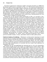
the following text. See Figures 10-1 and 10-2, which show various manlift arrangements with
component names that will be used in this chapter.
10.1.2 Purpose
The purpose of this inspection is to review the entire manlift installation to ascertain that the
equipment is being properly maintained and is in a safe operating status. Because the operation
and use of manlifts are by nature very dangerous, the inspection should be directed toward those
areas such as safety ropes, limit switches, belt integrity and guards, standing and boarding
surfaces and the treads and handholds that directly relate to the safe operation by the user
personnel.
10.1.3 Use
Manlifts are generally used to transport working personnel in flour and feed mills, paper pulp
plants, warehouses, filtration plants, power plants, chemical plants, and parking garages. They
are provided for the exclusive use of certain designated operating or maintenance personnel when
vertical transportation of such persons is required for a distance of two or more floors. No
persons other than such employees are permitted to ride on the units.
10-1
Simpo PDF Merge and Split Unregistered Version -
10-2
Simpo PDF Merge and Split Unregistered Version -
10-3
Simpo PDF Merge and Split Unregistered Version -
10.1.4 Applicable Safety Standards
The applicable safety standards for the construction, maintenance, inspection and operation of
manlifts is contained in ANSI A90.1-1976 Safety Standard for Manlifts and section 1910.68 of
the Federal OSHA Standards for Manlifts. Many state and municipal code inspection authorities
also publish safety standards for manlifts. Because there have been many incidences of
accidents to persons on or about manlifts with numerous fatalities, a number of local code
enforcement bodies have outlawed their use. The Navy does not allow any new manlifts to be
installed for this very reason.
10.1.5 Inspection Interval
Both the A90.1 Code and the OSHA Section 1910.68 require the periodic inspection of the
following items at not more than 30 day intervals:
a. Belt and Belt Joints
b. Bottom (Boot) Pulley and Clearances
c. Bottom Pulley Supports
d. Bottom Pulley Takeup
e. Brake
f. Drive Mechanism and Couplings
g. Electrical Switches
h. Floor Landings - Slippery Conditions
i. Guardrails
j. Handhold Fastenings
k. Illumination
l. Limit Switches
m. Lubrication
n. Drive Motor & Coupling
o. Pulley Lagging
p. Pulley Supports
q. Rail Supports and Fastenings
r. Rail/Track
s. Rollers and Slides
t. Rope Control Stop
u. "Skip" on Up or Down Run When Mounting Step (Indicating Worn Gears)
v. Steps
w. Step Fastenings
x. Top Pulley
y. Vibration and Misalignment
z. Warning Signs and Lights
aa. Safety stops - inspect weekly
10-4
Simpo PDF Merge and Split Unregistered Version -
Man Lift found to be unsafe shall not be operated until properly repaired. Limit switches should
be checked weekly. The sample Belt Manlift Inspection Report included at the end of this
chapter was taken from the appendix of the A90.1 Standard should be utilized for recording the
weekly and monthly inspections.
10.2 INSPECTION PROCEDURES
10.2.1 Controlled Access
When manlifts are located in buildings, such as parking garages, to which the public has
access, make certain they are located in an enclosure protected by self-closing, spring-locked
doors, at all floors to which the public has access. Keys to such doors shall be limited to
employees. In lieu of spring-locked doors, which require a key, a magnetic-type lock is
permitted if the actuating pushbutton is located not less than seven feet above the floor in an
inconspicuous location.
10.2.2 Floor Openings
Floor openings for a manlift should be uniform in size, be approximately circular, and be
located vertically above the opening below it. Floor openings for both up and down runs should
generally conform to the following:
Belt Width Floor Opening Width
(in inches) (in inches)
12 28 - 32
14 34 - 48
16 36 - 40
Floor openings should extend not less than 24 inches nor more than 28 inches from the face of
the belt.
10.2.3 Illumination
Adequate lighting of not less than three foot-candles should be provided at each floor landing
at all times when the manlift is in operation. Check with a calibrated light meter. Both runs of a
manlift should be illuminated at all times when it is in operation. A level of not less than one
foot-candle should be maintained at all points.
10.2.4 Landings
The floor space adjacent to floor openings should be free from obstruction and kept clear at all
10-5
Simpo PDF Merge and Split Unregistered Version -
times. The landing surfaces at the entrances and exits to manlifts should be so constructed and
maintained as to provide safe footing at all times. When there is a travel of 50 feet or more
between floor landings, one or more emergency platforms should be provided so that there is a
landing, either floor or emergency, for every 25 feet or less of travel. Such emergency landings
should be accessible from both runs of the manlift and should give access to emergency exit
ladders. Emergency platforms should be enclosed with a standard railing and toeboard.
10.2.5 Landing Guards
On the ascending side of a manlift, the landings should be provided with a bevel guard or
cone (See Figure 10-3) meeting the following requirements:
a. The cone should make an angle of not less than 45 degrees with the horizontal. An angle
of 60 degrees or greater may be used where ceiling heights permit.
b. The guard should extend at least 36 inches outward from the face of the belt, but not
beyond the upper surface of the floor above.
c. The cone should be made of not less than No. 18 U.S. gage sheet steel or material of
equivalent strength or stiffness. The lower ledge should be rolled to a minimum diameter of 1/2
inch and the interior should be smooth with no rivets, bolts, or screws protruding.
d. It should be noted that cones on the down run of the belt serve as fairly effective fire stops
and tend to prevent the loss of warm air from lower floors.
10.2.6 Floor Opening Guards
The floor opening at each landing should be guarded on sides not used for entrance or exit by
a standard railing and toeboard or by approved panels or wire mesh. Such rails or guards should
be at least 42 inches in height on the up-running side and 66 inches on the down-running side.
Rails or guards should be located not more than one foot from the edge of the floor opening.
10.2.7 Protection Of Entrances And Exits
The entrances and exits at all floors or landings affording access to a manlift should be
guarded by a maze (staggered railing) or a handrail equipped with self-closing gates. Such rails
should be standard OSHA approved guardrails with toeboards. Gates, if used, should open
outward and be self-closing. Corners of such gates should be rounded. Maze or staggered
openings should offer no direct passage between enclosure and outer floor space.
10-6
Simpo PDF Merge and Split Unregistered Version -
10-7
Simpo PDF Merge and Split Unregistered Version -
10.2.8 Bottom Arrangement
At the bottom landing the clear area should not be smaller than the area enclosed by the
guardrails on the floors above, and any wall in front of the down-running side of the belt should
be not less than 48 inches from the face of the belt. Such space should not be encroached upon
by stairs or ladder. The lower, or boot pulley should be installed so that it is supported by the
lowest landing served. A mounting platform should be provided in front or to one side of the
up-run at the lowest landing, unless the floor level is such that the floor or platform is at or above
the point at which the upper surface of the ascending step assumes a horizontal position.
10.2.9 Top Clearances
A minimum top clearance of 11 feet should be provided above the top terminal landing. No
encroachment of structural or machine-supporting members within such space is permitted.
There should be a clearance of at least five feet between the center of the head pulley shaft and
any ceiling obstruction. The center of the head-pulley shaft should not be less than six feet above
the top terminal landing.
10.2.10 Emergency Exit Ladders
A fixed metal ladder accessible from both the up and down-run of the manlift should be
provided when the vertical distance between landings exceeds 20 feet.
10.2.11 Drive Machine
10.2.11.1 Type. Machines can be of the direct-connected type or driven by multiple V-belts.
Cast iron gears should not be used.
10.2.11.2 Brake. A mechanically-applied, electrically released brake must be applied to the
motor shaft for direct connected units or to the input shaft for belt-driven units. The brake should
be capable of stopping and holding the manlift when the descending side is loaded with 250
pounds on each step. observe the brake operation to make certain it applies when the manlift is
stopped and electrically releases when the unit is started.
10.2.12 Belt
10.2.12.1 Material. The belts can be made of hardwoven canvas, rubber-coated canvas, leather,
or other material meeting the strength requirements of the applicable codes and having a
coefficient of friction such that when it is used in conjunction with an adequate tension device, it
will meet the brake test specified in the applicable codes.
10-8
Simpo PDF Merge and Split Unregistered Version -
10.2.12.2 Width. The width of belts should conform to the following:
Minimum Width Total Travel
(in inches) (in feet)
12 0 - 100
14 100 - 150
16 More than 150
10.2.12.3 Strength. The strength of belts should be not less than 1,500 pounds per inch of belt
width for belts having a distance between pulley centers not in excess of 100 feet, and 1,800
pounds per inch of belt width for belts having a distance between pulley centers of over 100 feet,
but not in excess of 200 feet for over 200 feet, 2,450 pounds per inch of belt width.
10.2.13 Belt Fastenings
Belts can be fastened by a lapped splice or by a butt-splice with a strap on each side of the belt
as follows:
a. For lapped splices, the overlap of the belt at the splice must be not less than three feet
when the total travel of the manlift does not exceed 100 feet and not less than four feet if the
travel exceeds 100 feet.
b. When butt splices are used, the straps must extend at least three feet on one side of the butt
for travel, not in excess of 100 feet, and four feet for travel in excess of 100 feet.
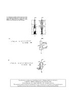
For 12 inch belts, the joint must be fastened with not less than 20 special elevator bolts, each of a
minimum diameter of 1/4 inch. Such bolts shall be arranged symmetrically in five rows so
arranged as to cover the area of the joint effectively. Reference should be made to Figures 10-4
and 10-5. Observe the proper belt splicing procedures. The minimum number of bolts for a belt
width of 14 inches shall be not less than 23 and for belt widths of 16 inches, the number of bolts
shall be not less than 27.
10.2.14 Pulleys
Drive pulleys and idler or boot pulleys should have a diameter of not less than 20 inches.
10.2.15 Pulley Protection
The machine must be so designed and constructed as to catch and hold the driving pulley in
the event of shaft failure.
10-9
Simpo PDF Merge and Split Unregistered Version -
10-10
Simpo PDF Merge and Split Unregistered Version -