Toyota camry hybrid xv50 2012 2017 wiper and washer gạt mưa rửa kính
Bạn đang xem bản rút gọn của tài liệu. Xem và tải ngay bản đầy đủ của tài liệu tại đây (1.8 MB, 31 trang )
WIPER AND WASHER – WIPER AND WASHER SYSTEM
WW–1
WIPER AND WASHER SYSTEM
PRECAUTION
NOTICE:
When disconnecting the cable from the negative (-)
battery terminal, initialize the following system after the
terminal is reconnected.
System Name
See procedure
SFI system
IN-43
1.
PRECAUTION OF WASHER NOZZLE ADJUSTMENT
(a) Do not clean or adjust the washer nozzle with a
safety pin, etc. because:
(1) the washer nozzle tip is made of resin and could
be damaged.
(2) adjustment is not necessary for this spray type
washer nozzle. If it is necessary to change the
nozzle angle, replace the washer nozzle with
one that has a different nozzle angle. (See page
WW-27)
(b) In case the washer nozzle is clogged with wax, etc.,
remove it and clean the nozzle hole with a soft resin
brush or other cleaning tool.
WW
WW–2
WIPER AND WASHER – WIPER AND WASHER SYSTEM
PARTS LOCATION
WASHER NOZZLE
FRONT WIPER ARM AND
BLADE ASSEMBLY LH
FRONT WIPER ARM AND
BLADE ASSEMBLY RH
WW
WINDSHIELD WIPER MOTOR
AND LINK ASSEMBLY
- FRONT WIPER MOTOR
WINDSHIELD WASHER JAR
AND PUMP ASSEMBLY
- WINDSHIELD WIPER
LINK ASSEMBLY
- FRONT WASHER MOTOR
ENGINE ROOM J/B AND R/B
- WASHER FLUID LEVEL
WARNING SWITCH
- ALT FUSE
WIPER SWITCH
MAIN BODY ECU
(INSTRUMENT PANEL J/B)
- IG1 RELAY
- WIP FUSE
- WASH FUSE
E119081E02
WW–3
WIPER AND WASHER – WIPER AND WASHER SYSTEM
SYSTEM DIAGRAM
Windshield Wiper Switch Assembly
Wiper Control Switch
+B
+2
+1
+S
INT1
INT2
B1
MIST
Washer Switch
OFF
W
INT
LO
OFF
HI
ON
EW
WW
Tr2
Front Wiper
Relay Circuit
Tr1
C2
C1
+2
+1
+S
+B
Washer Motor
LO
HI
Front Wiper Motor
E119103E01
WW–4
WIPER AND WASHER – WIPER AND WASHER SYSTEM
SYSTEM DESCRIPTION
1.
WW
2.
WASHER LINKED OPERATION
(a) This system operates the front wipers at a low
speed immediately after a jet of washer fluid when
the front washer switch is turned on for
approximately 0.3 seconds or more. If the switch is
turned off within approximately 1.5 seconds, the
system stops the wipers when the switch is turned
off. If the switch is turned on for approximately 1.5
seconds or more, the system stops the wipers
approximately 2.2 seconds after the switch is turned
off.
INTERMITTENT OPERATION
(a) The system operates the front wipers once in
approximately 1.6 to 10.7 seconds when the front
wiper switch is turned to the INT position. The
intermittent time can be adjusted between 1.6 and
10.7 seconds.
WIPER AND WASHER – WIPER AND WASHER SYSTEM
WW–5
(b) If the wiper control switch is turned to the INT
position, current flows from the already charged
capacitor C1 to Tr1 (transistor) through terminals
INT1 and INT2 of the wiper control switch. When
Tr1 turns on, current flows from terminal +S of the
wiper control switch to terminal +1 of the wiper
control switch, to terminal +1 of the wiper motor, to
the wiper motor and finally to the ground, causing
the wiper motor to operate. At the same time,
current flows from capacitor C1 to terminal INT1 of
the wiper control switch and then INT2. When the
current flow from capacitor C1 ends, Tr1 turns off to
stop the relay contact point and halt the wiper motor.
When the relay contact point turns off, capacitor C1
begins to charge again and Tr1 remains off until
charging has been completed. This period
corresponds to the intermittent time. When
capacitor C1 is fully charged, Tr1 turns on and then
the relay contact point activates, causing the motor
to operate. This cycle is the intermittent operation.
The intermittent time can be adjusted by using the
intermittent time adjust dial (variable resistor) to
change the charge time of capacitor C1.
WW
WW–6
WIPER AND WASHER – WIPER AND WASHER SYSTEM
Windshield Wiper Switch Assembly
Wiper Control Switch
+B
+2
+1
+S
INT1
INT2
B1
MIST
Washer Switch
OFF
INT
W
LO
OFF
HI
ON
EW
WW
Tr2
Front Wiper
Relay Circuit
Tr1
C2
C1
+2
+1
+S
+B
Washer Motor
LO
HI
Front Wiper Motor
E119104E01
WIPER AND WASHER – WIPER AND WASHER SYSTEM
3.
WW–7
WASHER FLUID LEVEL WARNING
(a) When the volume of washer fluid decreases to
below a certain level (when the washer fluid level
warning switch is turned ON), the combination
meter assembly warns the driver through the master
warning light illumination, the buzzer and the
warning message on the multi-information display.
WW
WW–8
WIPER AND WASHER – WIPER AND WASHER SYSTEM
PROBLEM SYMPTOMS TABLE
HINT:
• Use the table below to help determine the cause of the
problem symptom. The potential cases of the symptoms
are listed in order of probability in the "Suspected Area"
column of the table. Check each symptom by checking the
suspected areas in order they are listed. Replace parts as
necessary.
• Inspect the fuses and relays related to the system before
inspecting the suspected areas below.
FRONT WIPER AND WASHER SYSTEM:
Symptom
WW
Suspected Area
1. IG1 relay
Front wiper system does not operate.
Front wipers do not operate in LO or HI.
Front wipers do not operate in INT.
Front washer motor does not operate.
Front wipers do not operate when the front washer
switch is ON.
See page
-
2. WIP fuse
-
3. Windshield wiper switch assembly
WW-21
4. Windshield wiper motor assembly
WW-11
5. Wire harness or connector
-
1. Windshield wiper switch assembly
WW-21
2. Windshield wiper motor assembly
WW-11
3. Wire harness or connector
-
1. Windshield wiper switch assembly
WW-21
2. Windshield wiper motor assembly
WW-11
3. Wire harness or connector
-
1. WASH fuse
-
2. Windshield wiper switch assembly
WW-21
3. Windshield washer motor assembly
WW-24
4. Wire harness or connector
-
1. Windshield wiper switch assembly
WW-21
2. Windshield wiper motor assembly
WW-11
3. Wire harness or connector
-
Washer fluid does not operate.
Washer hose and nozzle
WW-26
When the front wiper switch is in the HI position, the
wiper blade is in contact with the body.
1. Front wiper arm installation position
WW-12
2. Windshield wiper motor assembly
WW-11
When the front wiper switch is OFF, the wiper blade
does not retract or retracts in a wrong position.
1. Front wiper arm installation position
WW-12
2. Windshield wiper motor assembly
WW-11
Others:
Symptom
Washer fluid level warning system does not operate.
Suspected Area
See page
1. Washer fluid level warning switch
WW-24
2. Combination meter assembly
-
WW–8
WIPER AND WASHER – FRONT WIPER MOTOR
FRONT WIPER MOTOR
BODY ELECTRICAL
WIPER
AND WASHER
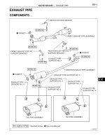
COMPONENTS
FRONT WIPER ARM AND
BLADE ASSEMBLY RH
20 (204, 15)
20 (204, 15)
FRONT WIPER ARM AND
BLADE ASSEMBLY LH
WW
FRONT FENDER TO
COWL SIDE SEAL RH
COWL TOP VENTILATOR LOUVER
SUB-ASSEMBLY
7.5 (77, 66 in.*lbf)
WINDSHIELD WIPER MOTOR
AND LINK ASSEMBLY
FRONT FENDER TO
COWL SIDE SEAL LH
5.4 (55, 48 in.*lbf)
WINDSHIELD WIPER LINK ASSEMBLY
WINDSHIELD WIPER MOTOR ASSEMBLY
N*m (kgf*cm, ft.*lbf) : Specified torque
Apply MP grease
E128804E01
WIPER AND WASHER – FRONT WIPER MOTOR
WW–9
REMOVAL
1.
REMOVE FRONT WIPER ARM AND BLADE
ASSEMBLY LH
(a) Remove the nut, and the front wiper arm and blade
assembly LH.
2.
REMOVE FRONT WIPER ARM AND BLADE
ASSEMBLY RH
(a) Remove the nut, and the front wiper arm and blade
assembly RH.
E136086
E135600
3.
REMOVE FRONT FENDER TO COWL SIDE SEAL LH
(a) Disengage the claw and remove the front fender to
cowl side seal LH.
4.
REMOVE FRONT FENDER TO COWL SIDE SEAL RH
(a) Disengage the claw and remove the front fender to
cowl side seal RH.
E128809
E128810
WW
WW–10
WIPER AND WASHER – FRONT WIPER MOTOR
5.
REMOVE COWL TOP VENTILATOR LOUVER SUBASSEMBLY
(a) Remove the 2 clips.
(b) Disengage the 4 claws and remove the cowl top
ventilator louver sub-assembly.
6.
REMOVE WINDSHIELD WIPER MOTOR AND LINK
ASSEMBLY
(a) Disconnect the connector.
WW
E135601
E135602
(b) Remove the 4 bolts and the windshield wiper motor
and link assembly.
E135603
7.
Protective
Tape
E128814E01
REMOVE WINDSHIELD WIPER MOTOR ASSEMBLY
(a) Using a screwdriver, separate the No. 2 windshield
wiper link rod from the crank arm pivot of the front
wiper motor assembly as shown in the illustration.
HINT:
Tape the screwdriver tip before use.
WIPER AND WASHER – FRONT WIPER MOTOR
WW–11
(b) Move the crank arm in the direction indicated by the
arrow.
E128815
(c) Remove the 3 bolts and the windshield wiper motor
assembly from the windshield wiper link assembly.
E128816
Connector Front View:
B1
INSPECTION
B
1.
+2
+1
+S
E
E034081E37
INSPECT WINDSHIELD WIPER MOTOR ASSEMBLY
(a) LO Operation Check
(1) Connect a positive (+) battery lead to terminal
B1-5 (+1) of the connector, and a negative (-)
battery lead to terminal B1-4 (E), and check
that the motor operates at low speed (LO).
(b) HI Operation Check
(1) Connect a positive (+) lead to terminal B1-3
(+2) of the connector, and a negative (-) battery
lead to terminal B1-4 (E), and check that the
motor operates at high speed (HI).
(c) Automatic Stop Operation Check
(1) Put matchmarks on the windshield wiper motor
assembly. The matchmarks will be used to
confirm the return of the motor shaft to the park
position.
22° +5°
-10°
Automatic Stop Position
B131458E03
WW
WW–12
WIPER AND WASHER – FRONT WIPER MOTOR
(2) Connect a positive (+) battery lead to terminal
B1-5 (+1) of the connector on the wiper motor
and connect a negative battery lead to terminal
B1-4 (E) of the wiper motor. With the motor
operating at low speed (LO), disconnect
terminal B1-5 (+1) to stop the wiper motor at a
position where the matchmarks do not line up.
HINT:
In the following step, connections will be made
at the wiper motor to allow verification of the
operation of the park contacts that are operated
by the cam in the wiper motor. After the
connections have been made, when the motor
is not in the park position, current will flow from
terminal B1-2 (B) through the park contacts in
the wiper motor, to terminal B1-1 (+S). The
current will then flow through the jumper wire to
terminal B1-5 (+1) through the motor to ground
(causing it to operate). When the motor
reaches the park position, the park contacts
should open, stopping the operation of the
wiper motor in the correct location. Terminals
B1-2 (B) and B1-1 (+S) are connected by the
internal cam in the wiper motor when the wiper
motor is not in the park position. Terminals B1-1
(+S) and B1-4 (E) are connected by the internal
cam in the wiper motor when the wiper motor is
in the park position.
(3) With the ground wire still attached from the
previous step, connect a jumper lead between
terminal B1-1 (+S) and terminal B1-5 (+1).
Next, connect a positive (+) battery lead to
terminal B1-2 (B) to cause the wiper motor to
operate at low speed. If the wiper motor is
operating correctly, the wiper will operate until it
reaches the park position. When it reaches the
park position, it will automatically stop.
(4) Verify that the matchmarks on the windshield
wiper motor assembly are lined up.
WW
INSTALLATION
1.
E128816
INSTALL WINDSHIELD WIPER MOTOR ASSEMBLY
(a) Install the windshield wiper motor assembly with the
3 bolts.
Torque: 5.4 N*m (55 kgf*cm, 48 in.*lbf)
WIPER AND WASHER – FRONT WIPER MOTOR
WW–13
(b) Move the crank arm in the direction indicated by the
arrow.
E128817
(c) Apply MP grease to the crank arm pivot of the
windshield wiper motor assembly.
E128818E01
(d) Install the No. 2 windshield wiper link rod to the pivot
of the windshield wiper motor assembly.
E128819E01
2.
(2)
(4)
(1)
(3)
INSTALL WINDSHIELD WIPER MOTOR AND LINK
ASSEMBLY
(a) Install the windshield wiper motor and link assembly
with the 4 bolts.
Torque: 7.5 N*m (77 kgf*cm, 66 in.*lbf)
NOTICE:
Tighten the bolts in the order shown in the
illustration.
E135603E01
(b) Connect the connector.
E135602
WW
WW–14
WIPER AND WASHER – FRONT WIPER MOTOR
3.
INSTALL COWL TOP VENTILATOR LOUVER SUBASSEMBLY
(a) Engage the 4 claws and install the cowl top
ventilator louver sub-assembly.
(b) Install the 2 clips.
4.
INSTALL FRONT FENDER TO COWL SIDE SEAL RH
(a) Engage the claw and install the front fender to cowl
side seal RH.
5.
INSTALL FRONT FENDER TO COWL SIDE SEAL LH
(a) Engage the claw and install the front fender to cowl
side seal LH.
6.
INSTALL FRONT WIPER ARM AND BLADE
ASSEMBLY LH
(a) Operate the wiper and stop the windshield wiper
motor at the automatic stop position.
WW
E135601
E128810
E128809
WW–15
WIPER AND WASHER – FRONT WIPER MOTOR
(b) Clean the wiper arm serrations.
(c) When reinstalling:
(1) Clean the wiper pivot serrations with a wire
brush.
Wiper Arm Serrations
Wire Brush
WW
Wiper Pivot Serrations
E112237E01
(d) Install the front wiper arm and blade assembly LH
with the nut to the position shown in the illustration.
Torque: 20 N*m (204 kgf*cm, 15 ft.*lbf)
HINT:
Hold the arm hinge by hand to fasten the nut.
Ceramic Notch
A
7.
Louver Edge
E128820E01
Area
Measurement
A
37 to 52 mm (1.46 to 2.05 in.)
INSTALL FRONT WIPER ARM AND BLADE
ASSEMBLY RH
(a) Operate the wiper and stop the windshield wiper
motor at the automatic stop position.
WW–16
WIPER AND WASHER – FRONT WIPER MOTOR
(b) Clean the wiper arm serrations.
(c) When reinstalling:
(1) Clean the wiper pivot serrations with a wire
brush.
Wiper Arm Serrations
Wire Brush
WW
Wiper Pivot Serrations
E112237E01
A
(d) Install the front wiper arm and blade assembly RH
with the nut to the position shown in the illustration.
Torque: 20 N*m (204 kgf*cm, 15 ft.*lbf)
HINT:
Hold the arm hinge by hand to fasten the nut.
Louver Edge
Ceramic Notch
E128821E01
Area
Measurement
A
23 to 38 mm (0.90 to 1.49 in.)
(e) Operate the front wipers while spraying washer fluid
on the windshield glass. Make sure that the front
wipers function properly and the wipers do not come
into contact with the vehicle body.
WIPER AND WASHER – FRONT WIPER RUBBER
WW–17
FRONT WIPER RUBBER
BODY ELECTRICAL
WIPER
AND WASHER
COMPONENTS
FRONT WIPER BLADE
WW
WIPER RUBBER
BACKING PLATE
WIPER RUBBER
WIPER RUBBER
BACKING PLATE
E119633E03
WW–18
WIPER AND WASHER – FRONT WIPER RUBBER
REMOVAL
1.
WW
REMOVE FRONT WIPER BLADE
(a) Disengage the holder of the front wiper blade.
(b) Remove the front wiper blade from the front wiper
arm as shown in the illustration.
NOTICE:
Do not bend the front wiper arm with the front
wiper blade removed because the arm tip could
damage the windshield surface.
Front Wiper Arm
Holder
Front Wiper Blade
E128822E01
2.
E125259
REMOVE WIPER RUBBER
(a) Remove the wiper rubber and the wiper rubber
backing plates from the front wiper blade.
WIPER AND WASHER – FRONT WIPER RUBBER
WW–19
(b) Remove the 2 wiper rubber backing plates from the
wiper rubber.
E125260E01
INSTALLATION
1.
E125260E02
INSTALL WIPER RUBBER
(a) Install the 2 wiper rubber backing plates to the wiper
rubber.
NOTICE:
• Align the protrusions on the wiper rubber
with the notches in the backing plates.
• Align the curves of the backing plates with
the curve of the glass.
(b) Install the wiper rubber to the front wiper blade with
the tip of the rubber (curved end) facing the axis of
the wiper arm.
NOTICE:
Firmly push the wiper rubber into the wiper
blade to securely engage them.
2.
E112266
INSTALL FRONT WIPER BLADE
(a) Install the front wiper blade as shown in the
illustration.
WW
WW–20
WIPER AND WASHER – FRONT WIPER RUBBER
(b) Engage the holder of the front wiper blade.
Front Wiper Arm
Holder
Front Wiper Blade
WW
E128823E01
WW–20
WIPER AND WASHER – WIPER SWITCH
WIPER SWITCH
BODY ELECTRICAL
WIPER
AND WASHER
COMPONENTS
WINDSHIELD WIPER SWITCH ASSEMBLY
WW
STEERING COLUMN COVER
2.0 (20, 18 in.*lbf)
N*m (kgf*cm, ft.*lbf) : Specified torque
E133793E01
WIPER AND WASHER – WIPER SWITCH
WW–21
REMOVAL
1.
REMOVE STEERING COLUMN COVER (See page
SR-36)
2.
REMOVE WINDSHIELD WIPER SWITCH ASSEMBLY
(a) Disconnect the 2 connectors.
(b) Disengage the claw and remove the windshield
wiper switch assembly as shown in the illustration.
NOTICE:
If the claw is pushed with excessive force, it
may break.
WW
E128824
INSPECTION
Connector Front View:
E20
1.
E19
E069286E04
INSPECT WINDSHIELD WIPER SWITCH ASSEMBLY
(a) Check the continuity of the windshield wiper switch
assembly.
(1) Measure the resistance according to the
value(s) in the table below.
Standard resistance:
Front Wiper Switch
Switch Position
Tester Connection
Specified Resistance
MIST
E20-2 (+B) - E20-3 (+1)
Below 1 Ω
OFF
E20-1 (+S) - E20-3 (+1)
Below 1 Ω
INT
E20-1 (+S) - E20-3 (+1)
Below 1 Ω
LO
E20-2 (+B) - E20-3 (+1)
Below 1 Ω
HI
E20-2 (+B) - E20-4 (+2)
Below 1 Ω
Front Washer Switch
Switch Position
Tester Connection
Specified Resistance
OFF
E19-3 (WF) - E19-2 (EW)
10 kΩ or higher
ON
E19-3 (WF) - E19-2 (EW)
Below 1 Ω
(b) Intermittent Operation Check
(1) Connect the voltmeter (+) terminal to terminal
E20-3 (+1) of the connector and the voltmeter
(-) terminal to terminal E19-2 (EW).
(2) Connect a positive (+) battery lead to terminal
E20-2 (+B) of the connector and a negative (-)
battery lead to terminals E19-2 (EW) and E20-1
(+S).
(3) Turn the wiper switch to the INT position.
(4) Connect a positive (+) battery lead to terminal
E20-1 (+S) of the connector for 5 seconds.
WW–22
WIPER AND WASHER – WIPER SWITCH
(5) Connect a negative (-) battery lead to terminal
E20-4 (+2) of the connector. Operate the
intermittent wiper adjustment ring and measure
the voltage between terminals E20-3 (+1) and
E19-2 (EW).
FAST:
SLOW:
10 to 14 V
E20-3 (+1) ←→ E19-2 (EW)
Voltage between terminals
WW
0V
1.6 +- 1 seconds
10.7 +- 5 seconds
E056399E31
INSTALLATION
E128825
1.
INSTALL WINDSHIELD WIPER SWITCH ASSEMBLY
(a) Engage the claw and install the windshield wiper
switch assembly as shown in the illustration.
(b) Connect the 2 connectors.
2.
INSTALL STEERING COLUMN COVER (See page SR41)
WIPER AND WASHER – FRONT WASHER MOTOR
WW–23
FRONT WASHER MOTOR
BODY ELECTRICAL
WIPER
AND WASHER
COMPONENTS
WINDSHIELD WASHER MOTOR AND PUMP ASSEMBLY
WW
RADIATOR GRILLE PROTECTOR
FRONT BUMPER ASSEMBLY
E133795E01