Toyota camry hybrid xv50 2012 2017 tire and wheel mâm và lốp
Bạn đang xem bản rút gọn của tài liệu. Xem và tải ngay bản đầy đủ của tài liệu tại đây (2.2 MB, 89 trang )
TIRE AND WHEEL – TIRE AND WHEEL SYSTEM
TW–1
TIRE AND WHEEL SYSTEM
PRECAUTION
NOTICE:
When disconnecting the cable from the negative (-)
battery terminal, initialize the systems after the cable is
reconnected (See page IN-43).
1. REMOVAL AND INSTALLATION OF THE TIRE
PRESSURE WARNING VALVE SUB-ASSEMBLY
(a) When installing a tire, make sure that the tire
pressure warning valve sub-assembly does not
interfere with the tire bead in order to prevent
damage to the tire pressure warning valve subassembly.
(b) After completing the operation, remove the valve
core to rapidly release the air in the tire and check
that the warning light comes on. If the warning light
does not come on, the system may be defective.
(c) If there is air leakage, tighten the nut to a torque of
4.0 N*m (41 kgf*cm, 35 in.*lbf) and push the valve
core 2 or 3 times to remove any dirt attached to the
valve core. If air continues to leak, replace the
grommet, washer, and nut.
(d) When installing the tire pressure warning valve subassembly, check whether the rim, grommet, washer,
and nut are clean. Use a manufacturer-specified
cap.
(e) When putting air into the tire, first install the tire
pressure valve straight onto the stem of the tire
pressure warning valve sub-assembly.
2. TIRE AND WHEEL REPLACEMENT
(a) If replacing a tire, be sure to check the grommet of
the tire valve for damage. If the grommet is
damaged, replace the grommet, washer, and nut.
(b) If tires and wheels are replaced, register the
transmitter ID (see page TW-14).
TW
TW–2
TIRE AND WHEEL – TIRE AND WHEEL SYSTEM
HOW TO PROCEED WITH
TROUBLESHOOTING
1.
Check that the wheel
nuts are fully tightened.
NG
Repair
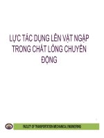
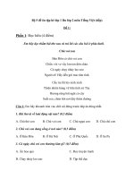
DIAGNOSIS OF TIRE VIBRATION
(a) Inspection procedure
NG
Inspect bearing looseness.
Inspect axle hub runout.
OK
Repair tire(s).
OK
OK
Return the vehicle
to the customer.
Check tire pressure.
OK
Check wheel balance.
OK
NG
Adjustment
TW
NG
Inspect bearing looseness.
Inspect axle hub runout.
Adjustment
NG
Repair
NG
OK
Check wheel balance.
C107882E08
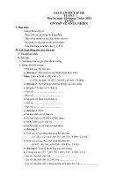
2.
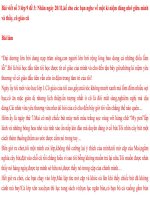
DIAGNOSIS OF IRREGULAR TIRE WEAR
(a) Inspection procedure
TIRE AND WHEEL – TIRE AND WHEEL SYSTEM
Check tire pressure.
NG
Adjustment
Rotate or replace
the tire(s).
Check wheel alignment.
OK
TW–3
OK
NG
Adjustment
NG
Check wheel alignment.
OK
C143924E01
TW
TW–4
TIRE AND WHEEL – TIRE AND WHEEL SYSTEM
INSPECTION
1.
INSPECT TIRE
(a) Check the tires for wear and proper inflation
pressure.
Cold tire inflation pressure
Tire size
Front kPa (kgf*cm2, psi)
Rear kPa (kgf*cm2, psi)
P215/60R16 94V
220 (2.2, 32)
220 (2.2, 32)
When driving under the above vehicle conditions at
sustained high speeds above 160 km/h (100 mph),
in countries where such speeds are permitted by
law, inflate the front and rear tires to 240 kPa (2.4
kgf*cm2, 35 psi) provided that it does not exceed the
maximum cold tire inflation pressure molded on the
tire sidewall.
(b) Using a dial indicator, check the runout of the tires.
Tire runout:
1.4 mm (0.055 in.) or less
C137874
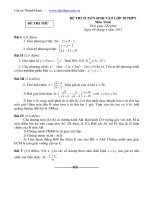
2.
Front
C140312E01
TW
ROTATE TIRES
HINT:
Rotate the tires as shown in illustration.
TIRE AND WHEEL – TIRE AND WHEEL SYSTEM
TW–5
3.
INSPECT WHEEL BALANCE
(a) Check and adjust the off-the-car balance.
Imbalance after adjustment:
8.0 g (0.018 lb.) or less.
NOTICE:
• Remove dirt, oil, and water from the surface
where the balance weight is to be adhered
with a cleaning detergent.
• Do not touch the sticking surface of the tape.
• Adhere the sticking type balance weight to
the flat position shown in the illustration.
• Push the balance weight securely with a
finger to adhere it to the indicated position.
• Do not reuse balance weights.
HINT:
• The inner side balance weight should be installed
by clipping it to the rim.
• If necessary, check and adjust the on-the-car
balance.
4.
INSPECT FRONT AXLE HUB BEARING LOOSENESS
HINT:
(See page AH-5)
5.
INSPECT REAR AXLE HUB BEARING LOOSENESS
HINT:
(See page AH-14)
6.
INSPECT FRONT AXLE HUB RUNOUT
HINT:
(See page AH-5)
7.
INSPECT REAR AXLE HUB RUNOUT
HINT:
(See page AH-14)
Approximately 25 mm (0.984 in.)
C144018E01
TW
TW–8
TIRE AND WHEEL – TIRE PRESSURE WARNING SYSTEM
PARTS LOCATION
COMBINATION METER ASSEMBLY
-TIRE PRESSURE WARNING LIGHT
TIRE PRESSURE WARNING RESET SWITCH
TIRE PRESSURE WARNING ECU
TIRE PRESSURE WARNING
VALVE AND TRANSMITTER
TIRE PRESSURE WARNING
VALVE AND TRANSMITTER
TW
TIRE PRESSURE WARNING
ANTENNA AND RECEIVER
TIRE PRESSURE WARNING
VALVE AND TRANSMITTER
TIRE PRESSURE WARNING
VALVE AND TRANSMITTER
E128787E02
TW–9
TIRE AND WHEEL – TIRE PRESSURE WARNING SYSTEM
SYSTEM DIAGRAM
Combination Meter
Tire Pressure Warning Valve
and Transmitter (Front LH)
- Vehicle Speed Signal
Tire Pressure Warning Valve
and Transmitter (Front RH)
Combination Meter
- Tire Pressure Warning Light
Tire pressure Warning
Antenna and Receiver
Tire Pressure
Warning ECU
DLC3
Tire Pressure Warning Valve
and Transmitter (Rear LH)
Tire Pressure Warning Valve
and Transmitter (Rear LH)
Tire Pressure Warning
Reset Switch
TW
: Radio Signal
C145704E01
TW–10
TIRE AND WHEEL – TIRE PRESSURE WARNING SYSTEM
SYSTEM DESCRIPTION
1.
DESCRIPTION OF SYSTEM
(a) A tire pressure warning valve and transmitter is
equipped with a tire pressure sensor and a
transmitter and is installed in a tire wheel assembly.
The sensor measures the tire pressure. The
measured value and transmitter ID are transmitted
to the tire pressure warning antenna and receiver on
the body as radio waves and then sent to the tire
pressure warning ECU from the tire pressure
warning antenna and receiver. If the transmitter ID
has already been registered, the ECU compares the
measured air pressure value with the standard
value. When the value is less than the standard
value registered in the tire pressure warning ECU,
the warning light on the combination meter comes
on.
• For the differences in the air pressure settings by
the type of tires, a tire pressure warning reset
switch has been adopted.
Tire Pressure Warning Valve and Transmitter
Tire Pressure Warning ECU
Tire Pressure Warning
Reset Switch
Tire Pressure
Warning Antenna
and Receiver
Combination Meter Assembly
- Tire Pressure Warning Light
TW
DLC3
Tire Pressure Warning Valve and Transmitter
C145706E01
2.
WHEN TIRE PRESSURE WARNING LIGHT IS LIT
(a) When the tire pressure warning light does not go off,
or when it comes on during driving, check tire
pressure. If the tire pressure warning light comes on
within several hours after adjusting the tire
pressure, the tire may have a slow air leak.
(b) Under the following conditions, the system may not
function properly.
• Facilities or devices that use similar radio
frequencies are located in the vicinity of the
vehicle.
TIRE AND WHEEL – TIRE PRESSURE WARNING SYSTEM
3.
Components
TW–11
• A radio device of similar frequency is used in the
vehicle.
• A large amount of snow or ice is stuck to the
vehicle, especially onto the wheels and around
the wheel houses.
• The battery of the sensor has been depleted.
• The tires without tire pressure warning valve and
transmitter are used.
• Tire chains are used.
• If any wheels other than the specified ones are
used, the system may not function properly
because interference may prevent the radio
waves from being correctly transmitted from the
tire pressure warning valve and transmitter.
• Depending on the tire type, the system may not
function properly even though the specified
wheels are used.
(c) The average usage life of the grommet of the tire
pressure warning valve and transmitter is
approximately 5 years, at which time it must be
replaced.
Re-tighten the valve nut if the valve is leaking air,
although it is less than 5 years old and there is no
problem with grommets.
(d) After removing and installing the ECU or a sensor,
check for a diagnostic code and verify that it is a
normal code.
FUNCTION OF COMPONENTS
Function
Tire pressure warning valve and transmitter
Combined as a single unit with a disc wheel air valve, it measures tire pressure and
temperature and transmits an ID number for measurement value and identification.
Built-in the battery.
Tire pressure warning antenna and receiver
Receives and transmits a necessary signal from the transmitter to the tire pressure
warning ECU.
Tire pressure warning ECU
Receives the signal from the receiver and identifies it as vehicle's own signal. If the
measured value is equal to or lower than the specified value, it transmits a signal so
that the air pressure warning light on the combination meter comes on.
Tire pressure warning light
Located in the combination meter, it informs the driver of lowered tire air pressure
and system failure.
Tire pressure warning reset switch
Enters the initialization mode for tire or wheel replacement.
4.
TIRE PRESSURE WARNING RESET SWITCH
• By operating the tire pressure warning reset switch,
the tire pressure warning ECU can be set to issue a
warning at an inflation pressure that corresponds to
the type of tires.
Therefore, the dealer must set the warning threshold
to the proper value in order to comply with the local
regulations.
• Operate the tire pressure warning reset switch only
after the inflation pressures of all tires have been
adjusted on the vehicle.
TW
TW–12
TIRE AND WHEEL – TIRE PRESSURE WARNING SYSTEM
• To initialize the system, press and hold the tire
pressure warning reset switch for 3 seconds or longer
with the power switch on (IG). After the initialization
process has started, the warning light blinks 3 times
(1 second on, 1 second off).
• During initialization, the tire pressure warning valve
and transmitter measures the inflation pressure of the
tires, and registers the signals that are transmitted
into the tire pressure warning ECU at a frequency of
once per minute. The initialization process is
completed when signals from the all tires have been
received.
TW
TW–36
TIRE AND WHEEL – TIRE PRESSURE WARNING SYSTEM
DIAGNOSTIC TROUBLE CODE CHART
HINT:
• If no abnormality is found when the parts are inspected,
inspect the tire pressure warning ECU.
• If a trouble code is displayed during the DTC check,
inspect the circuit listed for that code. For details of each
code, refer to the relevant page listed under respective
"DTC Code" in the DTC chart.
TIRE PRESSURE WARNING SYSTEM
DTC Code
Detection Item
Trouble Area
See page
C2111/11
Transmitter ID1 Operation Stop
1. Tire pressure warning valve
and transmitter
2. Tire pressure warning ECU
TW-34
C2112/12
Transmitter ID2 Operation Stop
1. Tire pressure warning valve
and transmitter
2. Tire pressure warning ECU
TW-34
C2113/13
Transmitter ID3 Operation Stop
1. Tire pressure warning valve
and transmitter
2. Tire pressure warning ECU
TW-34
C2114/14
Transmitter ID4 Operation Stop
1. Tire pressure warning valve
and transmitter
2. Tire pressure warning ECU
TW-34
C2121/21
No Signal from Transmitter ID1 in
Main Mode
1. Tire pressure warning valve
and transmitter
2. Tire pressure warning antenna
and receiver
3. Wire harness or connector
4. Tire pressure warning ECU
TW-36
C2122/22
No Signal from Transmitter ID2 in
Main Mode
1. Tire pressure warning valve
and transmitter
2. Tire pressure warning antenna
and receiver
3. Wire harness or connector
4. Tire pressure warning ECU
TW-36
C2123/23
No Signal from Transmitter ID3 in
Main Mode
1. Tire pressure warning valve
and transmitter
2. Tire pressure warning antenna
and receiver
3. Wire harness or connector
4. Tire pressure warning ECU
TW-36
C2124/24
No Signal from Transmitter ID4 in
Main Mode
1. Tire pressure warning valve
and transmitter
2. Tire pressure warning antenna
and receiver
3. Wire harness or connector
4. Tire pressure warning ECU
TW-36
C2141/41
Transmitter ID1 Error
1. Tire pressure warning valve
and transmitter
2. Tire pressure warning ECU
TW-43
C2142/42
Transmitter ID2 Error
1. Tire pressure warning valve
and transmitter
2. Tire pressure warning ECU
TW-43
C2143/43
Transmitter ID3 Error
1. Tire pressure warning valve
and transmitter
2. Tire pressure warning ECU
TW-43
C2144/44
Transmitter ID4 Error
1. Tire pressure warning valve
and transmitter
2. Tire pressure warning ECU
TW-43
C2165/65
Abnormal Temperature Inside ID1
Tire
1. Tires
2. Tire pressure warning valve
and transmitter
3. Tire pressure warning ECU
TW-46
TW
TW–37
TIRE AND WHEEL – TIRE PRESSURE WARNING SYSTEM
DTC Code
Detection Item
C2166/66
Abnormal Temperature Inside ID2
Tire
1. Tires
2. Tire pressure warning valve
and transmitter
3. Tire pressure warning ECU
TW-46
C2167/67
Abnormal Temperature Inside ID3
Tire
1. Tires
2. Tire pressure warning valve
and transmitter
3. Tire pressure warning ECU
TW-46
C2168/68
Abnormal Temperature Inside ID4
Tire
1. Tires
2. Tire pressure warning valve
and transmitter
3. Tire pressure warning ECU
TW-46
C2171/71
Transmitter ID not Registered
Tire pressure warning ECU
TW-49
C2176/76
Receiver Error
1. Tire pressure warning antenna
and receiver
2. Wire harness or connector
3. Tire pressure warning ECU
TW-51
C2177/77
Initialization not Completed
1. Tire pressure warning valve
and transmitter
2. Tire pressure warning ECU
3. Tire pressure warning antenna
and receiver
4. Tire pressure warning reset
switch
5. Wire harness or connector
TW-54
C2181/81
Transmitter ID1 not Received
(Test Mode DTC)
1. Tire pressure warning valve
and transmitter
2. Tire pressure warning antenna
and receiver
3. Wire harness or connector
4. Tire pressure warning ECU
TW-36
C2182/82
Transmitter ID2 not Received
(Test Mode DTC)
1. Tire pressure warning valve
and transmitter
2. Tire pressure warning antenna
and receiver
3. Wire harness or connector
4. Tire pressure warning ECU
TW-36
C2183/83
Transmitter ID3 not Received
(Test Mode DTC)
1. Tire pressure warning valve
and transmitter
2. Tire pressure warning antenna
and receiver
3. Wire harness or connector
4. Tire pressure warning ECU
TW-36
C2184/84
Transmitter ID4 not Received
(Test Mode DTC)
1. Tire pressure warning valve
and transmitter
2. Tire pressure warning antenna
and receiver
3. Wire harness or connector
4. Tire pressure warning ECU
TW-36
1. Vehicle speed sensor
2. Tire pressure warning ECU
3. Combination meter
4. Wire harness or connector
TW-61
C2191/91
Vehicle Speed Signal Error (Test
Mode DTC)
Trouble Area
See page
TW
TW–38
TIRE AND WHEEL – TIRE PRESSURE WARNING SYSTEM
DTC
C2111/11 Transmitter ID1 Operation Stop
DTC
C2112/12 Transmitter ID2 Operation Stop
DTC
C2113/13 Transmitter ID3 Operation Stop
DTC
C2114/14 Transmitter ID4 Operation Stop
DESCRIPTION
The tire pressure warning valve and transmitters that are installed in the tire and wheel assemblies
measure the air pressures of the tires. The measured values are transmitted to the tire pressure warning
antenna and receiver on the body as radio waves and then sent to the tire pressure warning ECU. The
ECU compares the measured air pressure values with the air pressure threshold. When the measured air
pressure value is less than this threshold, the warning light in the combination meter comes on. The tire
pressure warning ECU stores a DTC when the tire pressure warning valve and transmitter stops
transmitting signals. At this time, the signals can be forcibly transmitted by releasing the tire pressure
rapidly. The stored DTC is cleared when the signal transmission is resumed.
DTC No.
DTC Detecting Condition
C2111/11
C2112/12
C2113/13
C2114/14
Tire pressure warning valve and transmitters
stop transmitting signals
Trouble Area
•
•
Tire pressure warning valve and
transmitter
Tire pressure warning ECU
HINT:
It is necessary to perform the procedure to identify the tire pressure warning valve and transmitter that is
malfunctioning because it cannot be identified by the output DTC.
INSPECTION PROCEDURE
NOTICE:
It is necessary to perform initialization (See page TW-17) after registration (See page TW-14) of the
transmitter IDs into the tire pressure warning ECU after the ECU and/or valve and transmitter has
been replaced.
1
PERFORM FORCED TRANSMISSION OF TRANSMITTER ID OF ALL WHEELS
(a) Set the tire pressure to the specified value.
TW
Cold tire inflation pressure
Tire size
Front kPa (kgf/cm2, psi)
Rear kPa (kgf/cm2, psi)
P215/60R16 94V
220 (2.2, 32)
220 (2.2, 32)
(b) Connect the intelligent tester to the DLC3.
(c) Turn the power switch on (IG) and turn the tester on.
(d) Select "TIREPRESS" by following the prompts displayed
on the intelligent tester.
TIRE PRESSURE:
Tester Display
Measurement Item/Range
Normal Condition
Diagnostic Note
Actual tire inflation pressure
-
ID1 tire inflation pressure / min.:0
TIREPRESS1
kPa (0 kgf/cm2, 0 psi), max.:
637.5 kPa (6.48 kgf / cm2, 92.2
psi)
TW–39
TIRE AND WHEEL – TIRE PRESSURE WARNING SYSTEM
Tester Display
Measurement Item/Range
Normal Condition
Diagnostic Note
Actual tire inflation pressure
-
Actual tire inflation pressure
-
Actual tire inflation pressure
-
ID2 tire inflation pressure / min.:0
TIREPRESS2
kPa (0 kgf/cm2, 0 psi), max.:
637.5 kPa (6.48 kgf / cm2, 92.2
psi)
ID3 tire inflation pressure / min.:0
TIREPRESS3
kPa (0 kgf/cm2, 0 psi), max.:
637.5 kPa (6.48 kgf / cm2, 92.2
psi)
ID4 tire inflation pressure / min.:0
TIREPRESS4
kPa (0 kgf/cm2, 0 psi), max.:
637.5 kPa (6.48 kgf / cm2, 92.2
psi)
(e) Rapidly release the pressures from each wheel by
approximately 40 kPa (0.4 kgf / cm2, 5.8 psi) /30
seconds or more.
(1) Check that each tire pressure data displayed on the
intelligent tester screen has changed.
OK:
Each tire pressure data displayed on the
intelligent tester screen will change to the
value of the tire pressure.
NOTICE:
• It takes about 1 minute or more to display the
updated tire pressure data.
• When the "TIREPRESS" data has not
changed, reset the tire pressure to the
appropriate specified value and rotate the tire
90 to 270 degrees. Then rapidly release the
tire pressure and recheck it.
(2) After confirming that all of the tire pressure data
displayed on the intelligent tester screen have
changed, set the tire pressure to the appropriate
specified values.
HINT:
If the tire pressure data displayed on the intelligent
tester screen has not changed after rechecking, go
to other problem procedure (For malfunctions in
transmission or reception function (See page TW22).
NG
OK
END
INSPECT OTHER PROBLEM
(MALFUNCTION IN TRANSMISSION OR
RECEPTION FUNCTION)
TW
TW–40
TIRE AND WHEEL – TIRE PRESSURE WARNING SYSTEM
DTC
C2121/21 No Signal from Transmitter ID1 in Main Mode
DTC
C2122/22 No Signal from Transmitter ID2 in Main Mode
DTC
C2123/23 No Signal from Transmitter ID3 in Main Mode
DTC
C2124/24 No Signal from Transmitter ID4 in Main Mode
DTC
C2181/81 Transmitter ID1 not Received (Test Mode DTC)
DTC
C2182/82 Transmitter ID2 not Received (Test Mode DTC)
DTC
C2183/83 Transmitter ID3 not Received (Test Mode DTC)
DTC
C2184/84 Transmitter ID4 not Received (Test Mode DTC)
DESCRIPTION
The tire pressure warning valve and transmitters that are installed in the tire and wheel assemblies
measure the air pressure of the tires. The measured values are transmitted to the tire pressure warning
antenna and receiver on the body as radio waves and then sent to the tire pressure warning ECU. The
ECU compares the measured air pressure values with the air pressure threshold. When the measured air
pressure value is less than this threshold, the warning light in the combination meter comes on.
The tire pressure warning valve and transmitters constantly send radio waves to the tire pressure warning
antenna and receiver.
Under the following conditions below, the tire pressure warning antenna and receiver is unable to receive
the signals from the tire pressure warning valves and transmitters, and a DTC is stored.
• Facilities or devices that use similar radio frequencies are located in the vicinity of the vehicle.
• Devices using similar radio frequencies are used in the vehicle.
HINT:
When no signals are received for 51 minutes or more, a DTC is output.
DTCs from C2121/21 to C2124/24 can only be cleared by using the tester. DTCs from C2181/81 to
C2184/84 can be cleared when the transmitter in the tire pressure warning valve and transmitter sends a
forced transmission signal or test mode ends. DTCs from C2181/81 to C2184/84 are output only in test
mode.
TW
DTC No.
DTC Detecting Condition
Trouble Area
C2121/21
C2122/22
C2123/23
C2124/24
These DTCs are detected when no signals are received
for 51 minutes or more.
•
•
•
•
Tire pressure warning valve and transmitter
Tire pressure warning antenna and receiver
Wire harness or connector
Tire pressure warning ECU
C2181/81
C2182/82
C2183/83
C2184/84
Malfunctions in the transmitting/receiving circuit
•
•
•
•
Tire pressure warning valve and transmitter
Tire pressure warning antenna and receiver
Wire harness or connector
Tire pressure warning ECU
HINT:
It is necessary to perform the procedure to identify the tire pressure warning valve and transmitter that is
malfunctioning because it cannot be identified by the output DTC.
TW–41
TIRE AND WHEEL – TIRE PRESSURE WARNING SYSTEM
WIRING DIAGRAM
Tire Pressure Warning ECU
5
+5V
Tire Pressure Warning
Antenna and Receiver
N20
1
RDA
N20
4
GND
N20
6
E60 RF5V
12
E60 RDA
11
E60 GND2
Tire Pressure Warning Valve
and Transmitter (Front RH)
Tire Pressure Warning Valve
and Transmitter (Front LH)
Tire Pressure Warning Valve
and Transmitter (Rear RH)
Tire Pressure Warning Valve
and Transmitter (Rear LH)
TW
: Radio Signal
C145271E02
INSPECTION PROCEDURE
NOTICE:
• When replacing the tire pressure warning ECU, read the IDs stored in the ECU using the
intelligent tester and write them down before removal.
• It is necessary to perform initialization (See page TW-17) after registration (See page TW-14) of
the transmitter IDs into the tire pressure warning ECU after the ECU and/or valve and
transmitter has been replaced.
TW–42
1
TIRE AND WHEEL – TIRE PRESSURE WARNING SYSTEM
CHECK FREQUENCY RECEIVING CONDITION
(a) Check if the vehicle is not located in areas such as
described below:
(1) Facilities or devices that use similar radio
frequencies are located in the vicinity of the vehicle.
HINT:
If the vehicle is located in areas described above,
the tire pressure warning light may come on only in
a particular area.
(2) Devices using similar radio frequencies are used in
the vehicle.
OK:
Facilities, or devices that use similar radio
frequencies are not located in the vicinity of
the vehicle.
HINT:
Radio frequency may be interrupted due to
surroundings or devices installed by the user.
NG
CHECK IF ANY DEVICE IS INSTALLED BY
USER
OK
2
IDENTIFY TRANSMITTER CORRESPONDING TO DTC
(a) Set the tire pressure to the appropriate specified values.
Cold tire inflation pressure
Tire size
Front kPa (kgf/cm2, psi)
Rear kPa (kgf/cm2, psi)
P215/60R16 94V
220 (2.2, 32)
220 (2.2, 32)
(b) Select "TIREPRESS" by following the prompts displayed
on the intelligent tester.
TIRE PRESSURE:
Tester Display
Measurement Item/Range
Normal Condition
Diagnostic Note
Actual tire inflation pressure
-
Actual tire inflation pressure
-
Actual tire inflation pressure
-
Actual tire inflation pressure
-
ID1 tire inflation pressure/
TW
TIREPRESS1
min.: 0 kPa (0 kgf/cm2, 0 psi), max.:
637.5 kPa (6.48 kgf/cm2, 92.2 psi)
ID2 tire inflation pressure/
TIREPRESS2
min.: 0 kPa (0 kgf/cm2, 0 psi), max.:
637.5 kPa (6.48 kgf/cm2, 92.2 psi)
ID3 tire inflation pressure/
TIREPRESS3
min.: 0 kPa (0 kgf/cm2, 0 psi), max.:
2
637.5 kPa (6.48 kgf/cm , 92.2 psi)
ID4 tire inflation pressure/
TIREPRESS4
min.: 0 kPa (0 kgf/cm2, 0 psi), max.:
637.5 kPa (6.48 kgf/cm2, 92.2 psi)
(c) Rapidly reduce the tire pressure for each wheel at least
40 kPa (0.41 kg/cm2, 5.8 psi) within 30 seconds.
(d) Check the DATA LIST.
TW–43
TIRE AND WHEEL – TIRE PRESSURE WARNING SYSTEM
NOTICE:
• It takes about 1 minute or more to display the
updated tire pressure data.
• When no "TIREPRESS" data has changed, reset
the tire pressure to the appropriate specified
value and rotate the tire 90 to 270 degrees. Then
rapidly release the tire pressure and recheck it.
• Record the transmitter ID of which "TIREPRESS"
data corresponds to each tire.
(e) After confirming that one of the "TIREPRESS" data for
one tire (ID1 to ID4) has changed, repeat this procedure
one by one. Identify the transmitter that corresponds to
the DTC.
Result
Condition
Proceed to
One or more of transmitters
abnormal
A
All normal
B
All abnormal
C
A
Go to step 4
B
END
C
3
CHECK HARNESS AND CONNECTOR (ECU - RECEIVER)
Wire Harness Side Connector Front View:
Tire Pressure Warning ECU
(a) Disconnect the E60 ECU connector.
(b) Disconnect the N20 receiver connector.
(c) Measure the resistance according to the value(s) in the
table below.
Standard resistance
RF5V
E60
RDA
GND2
N20
E60-11 (GND2) - N20-4 (GND)
Specified Condition
+5V
RDA
GND
E129461E12
Below 1 Ω
E60-6 (RF5V) - N20-5 (+5V)
NG
Tire Pressure Warning
Antenna and Receiver
OK
Tester Connection
E60-12 (RDA) - N20-1 (RDA)
REPAIR OR REPLACE HARNESS OR
CONNECTOR
TW
TW–44
4
TIRE AND WHEEL – TIRE PRESSURE WARNING SYSTEM
INSPECT TIRE PRESSURE WARNING VALVE AND TRANSMITTER
(a) Select REGIT ID CODE by following the prompts
displayed on the intelligent tester.
TIRE PRESSURE:
Tester Display
Measurement Item/Range
Normal Condition
Diagnostic Note
REGIT ID1 CODE
Registered ID1 code/
min.: 0, max.: FFFFFF*
The ID No. registered in the
transmitter ID1 is displayed
*: Displayed only when the ID
No. is not registered.
REGIT ID2 CODE
Registered ID2 code/
min.: 0, max.: FFFFFF*
The ID No. registered in the
transmitter ID2 is displayed
*: Displayed only when the ID
No. is not registered.
REGIT ID3 CODE
Registered ID3 code/
min.: 0, max.: FFFFFF*
The ID No. registered in the
transmitter ID3 is displayed
*: Displayed only when the ID
No. is not registered.
REGIT ID4 CODE
Registered ID4 code/
min.: 0, max.: FFFFFF*
The ID No. registered in the
transmitter ID4 is displayed
*: Displayed only when the ID
No. is not registered.
(b) Check the ID number on the identified transmitter by
removing it from the tire and wheel.
Tire Pressure warning valve and transmitter:
Transmitter ID
(7-digit number)
E128762E07
(c) Confirm that the ID number on the transmitter and
recorded transmitter ID match.
Result
TW
Result
Proceed to
Match
A
Do not match
B
B
Go to step 6
A
5
REPLACE TIRE PRESSURE WARNING VALVE AND TRANSMITTER
HINT:
(See page TW-75)
NEXT
TW–45
TIRE AND WHEEL – TIRE PRESSURE WARNING SYSTEM
6
REGISTRATION OF TRANSMITTER ID
(a) Perform registration (See page TW-14).
(b) Set the tire pressure to the appropriate specified values.
Cold tire inflation pressure
Tire size
Front kPa (kgf/cm2, psi)
Rear kPa (kgf/cm2, psi)
P215/60R16 94V
220 (2.2, 32)
220 (2.2, 32)
NEXT
7
PERFORM INITIALIZATION
(a) Perform initialization (See page TW-17).
NEXT
8
READ VALUE OF DATA LIST
(a) Turn the power switch off, and then turn it on (IG).
(b) Select "TIREPRESS" by following the prompts displayed
on the intelligent tester.
HINT:
It may take up to 1 minute or more to display the tire
pressure data.
Result
Condition
Proceed to
All tire pressure readings are equal to specified values.
A
Tire pressure values are not displayed.
B
A
END
B
9
REPLACE TIRE PRESSURE WARNING ANTENNA AND RECEIVER
(a) Replace the tire pressure warning antenna and receiver
(See page TW-72).
NEXT
10
READ VALUE OF DATA LIST
(a) Turn the power switch off, and then turn it on (IG).
(b) Select "TIREPRESS" by following the prompts displayed
on the intelligent tester.
HINT:
It may take up to 1 minute or more to display the tire
pressure data.
TW
TW–46
TIRE AND WHEEL – TIRE PRESSURE WARNING SYSTEM
Result
Condition
Proceed to
All tire pressure readings are equal to specified values.
A
Tire pressure values are not displayed.
B
B
A
END
TW
REPLACE TIRE PRESSURE WARNING ECU
(See page TW-79)
TW–47
TIRE AND WHEEL – TIRE PRESSURE WARNING SYSTEM
DTC
C2141/41 Transmitter ID1 Error
DTC
C2142/42 Transmitter ID2 Error
DTC
C2143/43 Transmitter ID3 Error
DTC
C2144/44 Transmitter ID4 Error
DESCRIPTION
The tire pressure warning valve and transmitters that are installed in the tire and wheel assemblies
measure the air pressure of the tires. The measured values are transmitted to the tire pressure warning
antenna and receiver on the body as radio waves and then sent to the tire pressure warning ECU. The
ECU compares the measured air pressure values with the air pressure threshold. When the measured air
pressure value is less than this threshold, the warning light in the combination meter comes on.
When the internal circuit of the tire pressure warning valve and transmitter is malfunctioning, this DTC is
output.
DTC No.
C2141/41
C2142/42
C2143/43
C2144/44
DTC Detecting Condition
If an "ERROR" signal is received 3 times consecutively,
the tire pressure warning valve and transmitter will be
judged as defective and a DTC will be output.
This will happen in situations where the inflation pressure
is outside the range 0 to 637.5 kPa (0 to 6.48 kgf/cm2, 0
psi to 92.2 psi), the temperature inside the tire is outside
the specified range -40 to 120°C (-40 to 248°F), or an
error occurs in the tire pressure warning valve and
transmitter or the surrounding area.
Trouble Area
•
•
Tire pressure warning valve and transmitter
Tire pressure warning ECU
HINT:
It is necessary to perform the procedure to identify the tire pressure warning valve and transmitter that is
malfunctioning because it cannot be identified by the output DTC.
INSPECTION PROCEDURE
NOTICE:
• When replacing the tire pressure warning ECU, read the IDs stored in the ECU using the
intelligent tester and write them down before removal.
• It is necessary to perform initialization (See page TW-14) after registration (See page TW-17) of
the transmitter IDs into the tire pressure warning ECU after the ECU and/or valve and
transmitter has been replaced.
1
IDENTIFY TRANSMITTER CORRESPONDING TO DTC
(a) Set the tire pressure to the specified value.
Cold tire inflation pressure
Tire size
Front kPa (kgf/cm2, psi)
Rear kPa (kgf/cm2, psi)
P215/60R16 94V
220 (2.2, 32)
220 (2.2, 32)
(b) Display the "TIREPRESS" data for each wheel using the
intelligent tester.
TW
TW–48
TIRE AND WHEEL – TIRE PRESSURE WARNING SYSTEM
(c) Rapidly reduce the tire pressure for each wheel at least
40 kPa (0.41 kg/cm2, 5.8 psi) within 30 seconds. If
"TIREPRESS" displayed on the tester (ID1 to ID4) does
not change, the tire pressure warning valve and
transmitter corresponds to the DTC that was detected.
HINT:
• Identify the malfunctioning tire pressure warning valve
and transmitter by repeatedly decreasing the tire
pressure for each tire.
• Record which "TIREPRESS" data (ID1 to ID4)
corresponds to each tire.
TIRE PRESSURE:
Tester Display
Measurement Item/Range
Normal Condition
Diagnostic Note
Actual tire inflation pressure
-
Actual tire inflation pressure
-
Actual tire inflation pressure
-
Actual tire inflation pressure
-
ID1 tire inflation pressure/
TIREPRESS1
min.: 0 kPa (0 kgf/cm2, 0 psi), max.:
637.5 kPa (6.48 kgf/cm2, 92.2 psi)
ID2 tire inflation pressure/
TIREPRESS2
min.: 0 kPa (0 kgf/cm2, 0 psi), max.:
637.5 kPa (6.48 kgf/cm2, 92.2 psi)
ID3 tire inflation pressure/
TIREPRESS3
min.: 0 kPa (0 kgf/cm2, 0 psi), max.:
2
637.5 kPa (6.48 kgf/cm , 92.2 psi)
ID4 tire inflation pressure/
TIREPRESS4
min.: 0 kPa (0 kgf/cm2, 0 psi), max.:
637.5 kPa (6.48 kgf/cm2, 92.2 psi)
(d) Check the DATA LIST.
Result
Condition
Detection Condition
One of "TIREPRESS" data (ID1 to ID4) changed.
Normal
"TIREPRESS" data did not change.
Transmitter corresponding to DTC
NOTICE:
• When the "TIREPRESS" data has not changed,
reset the tire pressure to the appropriate specified
value and rotate the tire 90 to 270 degrees. Then
forcibly transmit the transmitter ID and recheck.
• Record the transmitter ID and position of
transmitters that are normal.
(e) When the "TIREPRESS" data (ID1 to ID4) has changed,
repeat this procedure to identify the tire pressure
warning valve and transmitter that corresponds to a
DTC.
(f) When all of the "TIREPRESS" data (ID1 to ID4) have
changed, identify the malfunctioning tire pressure
warning valve and transmitter using recorded ID
numbers and output DTC.
(g) Set the tire pressures to the appropriate specified
values.
TW
NEXT
TW–49
TIRE AND WHEEL – TIRE PRESSURE WARNING SYSTEM
2
REPLACE TIRE PRESSURE WARNING VALVE AND TRANSMITTER
(a) Replace the identified tire pressure warning valve and
transmitter with a new one (See page TW-75).
HINT:
• Before installing a new tire pressure warning valve
and transmitter, read and write down its transmitter
ID.
• The IDs for the tire pressure warning valve and
transmitter not to be replaced should be checked
using the tester and recorded.
NEXT
3
REGISTRATION OF TRANSMITTER ID
(a) Register the transmitter ID for all wheels (See page TW14).
(b) Set the tire pressure to the specified value.
Cold tire inflation pressure
Tire size
Front kPa (kgf/cm2, psi)
Rear kPa (kgf/cm2, psi)
P215/60R16 94V
220 (2.2, 32)
220 (2.2, 32)
NEXT
4
PERFORM INITIALIZATION
(a) Perform initialization (See page TW-17).
NEXT
5
CHECK FOR DTC
(a) Check for a DTC (See page TW-28).
Result
Condition
Proceed to
Any of the DTCs from C2141/41 to C2144/44 are output.
A
Any of the DTCs from C2141/41 to C2144/44 are not output.
B
B
END
A
REPLACE TIRE PRESSURE WARNING ECU (See page TW-79)
TW
TW–50
TIRE AND WHEEL – TIRE PRESSURE WARNING SYSTEM
DTC
C2165/65 Abnormal Temperature Inside ID1 Tire
DTC
C2166/66 Abnormal Temperature Inside ID2 Tire
DTC
C2167/67 Abnormal Temperature Inside ID3 Tire
DTC
C2168/68 Abnormal Temperature Inside ID4 Tire
DESCRIPTION
Each tire pressure warning valve and transmitter measures the internal temperature of its tire as well as
tire pressure, and transmits the information to the tire pressure warning ECU along with the transmitter ID.
If the measured temperature is out of the specified range, the tire pressure warning ECU recognizes it as
a malfunction, outputs DTCs, and blinks the tire pressure warning light.
DTC No.
C2165/65
C2166/66
C2167/67
C2168/68
DTC Detecting Condition
Trouble Area
Temperature inside the tire exceeds 119°C (246.2°F)
more than once.
•
•
•
Tires
Tire pressure warning valve and transmitter
Tire pressure warning ECU
HINT:
It is necessary to perform the procedure to identify the tire pressure warning valve and transmitter that is
malfunctioning because it cannot be identified by the output DTC.
INSPECTION PROCEDURE
NOTICE:
• When replacing the tire pressure warning ECU, read the IDs stored in the ECU using the
intelligent tester and note them down before removal.
• It is necessary to perform initialization (See page TW-17) after registration (See page TW-14) of
the transmitter IDs into the tire pressure warning ECU after the ECU and/or valve and
transmitter has been replaced.
1
CHECK TIRES
(a) Check the tire is not flat, and there is no indication of air
pressure drop.
OK:
Tire is normal.
HINT:
If a tire is damaged, the tire pressure warning valve and
transmitter may also have been damaged at the same
time.
TW
NG
REPLACE TIRE AND TIRE PRESSURE
WARNING VALVE AND TRANSMITTER (See
page TW-75)
OK
2
IDENTIFY TRANSMITTER CORRESPONDING TO DTC
(a) Set the tire pressure to the specified value.