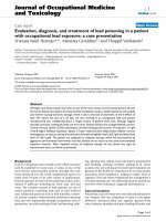
Báo cáo hóa học: " Direct Synthesis and Characterization of Optically Transparent Conformal Zinc Oxide Nanocrystalline Thin Films by Rapid Thermal Plasma CVD" pptx
Bạn đang xem bản rút gọn của tài liệu. Xem và tải ngay bản đầy đủ của tài liệu tại đây (4.34 MB, 12 trang )
NANO EXPRESS Open Access
Direct Synthesis and Characterization of Optically
Transparent Conformal Zinc Oxide Nanocrystalline
Thin Films by Rapid Thermal Plasma CVD
Joachim D Pedersen, Heather J Esposito and Kwok Siong Teh
*
Abstract
We report a rapid, self-catalyzed, solid precursor-based thermal plasma chemical vapor deposition process for
depositing a conformal, nonporous, and optically transparent nanocrystalline ZnO thin film at 130 Torr (0.17 atm).
Pure solid zinc is inductively heated and melted, followed by ionization by thermal induction argon/oxygen plasma
to produce conformal, nonporous nanocrystalline ZnO films at a growth rate of up to 50 nm/min on amorphous
and crystalline substrates including Si (100), fused quartz, glass, muscovite, c- and a-plane sapphire (Al
2
O
3
), gold,
titanium, and polyimide. X-ray diffraction indicates the grains of as-deposited ZnO to be highly textured, with the
fastest growth occurring along the c-axis. The individual grains are observed to be faceted by (103) planes which
are the slowest growth planes. ZnO nanocrystalline films of nominal thicknesses of 200 nm are deposited at
substrate temperatures of 330°C and 160°C on metal/ceramic substrates and polymer substrates, respectively. In
addition, 20-nm- and 200-nm-thick films are also deposited on quartz sub strates for optical characterization. At
optical spectra above 375 nm, the measured optical transmittance of a 200-nm-thick ZnO film is greater than 80%,
while that of a 20-nm-thick film is close to 100%. For a 200-nm-thick ZnO film with an average grain size of 100
nm, a four-point probe measurement shows electrical conductivity of up to 910 S/m. Annealing of 200-nm-thick
ZnO films in 300 sccm pure argon at temperatures ranging from 750°C to 950°C (at homologous temperatures
between 0.46 and 0.54) alters the textures and morphologies of the thin film. Based on scanning electron
microscope images, higher annealing temperatures appear to restructure the ZnO nanocrystalline films to form
nanorods of ZnO due to a combination of grain boundary diffusion and bulk diffusion.
PACS: films and coatings, 81.15 z; nanocrystalline materials, 81.07.Bc; II-VI semiconductors, 81.05.Dz.
Keywords: zinc oxide, transparent nanocrystalline film, thermal plasma chemical vapor deposition, annealing,
nanorods
Background
Zinc oxide [ZnO] is a direct, wide bandgap (E
g
=3.37
eV at room temperature) semiconductor which has a
high exciton binding energy (60 meV) [1-5]. The large
bandgap renders pure ZnO to be colorless in appear-
ance and non-absorbing in the visible to infrared wave-
lengths (optical spectra at and above 375 nm). The high
exciton binding energy of ZnO allows excitonic laser
action at or above room temperature, in addition to
making ZnO the brightest emitter among GaN (26
meV) and ZnSe (20 meV). From an electronic stand-
point, ZnO has one of the best conductivities among
the transparent conducting oxides [TCO] due to its
high charge carrier mobility - ZnO has high experimen-
tally derived electron Hall mobility of up to 200 cm
2
/V-
s [6,7] and hole mobi lities ranging from 2 to 8 cm
2
/V-s
[8,9]. These desirable attributes make ZnO suitable for
optoelectronic applications such as transparent thin
transistor [10,11], TCO and buffer layers in photovoltaic
cells [12,13], light-emitting diode [8,9], UV laser [14],
optical waveguide [15], and biochemical sensors [16]. In
spite of these desirable attributes, most current methods
of synthesizing ZnO thin films - including plasma
enhanced chemical vapor deposition [CVD] [17], ther-
mal CVD [18], radio frequency [RF] or DC magnetron
sputtering [19-21], metal organic chemical vapor
* Correspondence:
School of Engineering, San Francisco State University, San Francisco, CA, USA
Pedersen et al. Nanoscale Research Letters 2011, 6:568
/>© 2011 Pedersen et al; li censee Springer. This is an Open Access article distributed under the terms of the Creative Commons
Attribution License (http://creativecommons.o rg/licenses/by/2.0), which permits unrestricted use, distribution, and reproduction in
any medium, provided the original work is properly cited.
deposition [MOCVD] [22], spray pyrolysis [23], pulsed
laser deposition [24], thermal evaporation [25], hydro-
thermal [26], and sol-gel processes [27] - often require
substantial vacuum, expensive consumables (e.g., diethyl
zinc, dimethyl zinc, ZnO sputter target), catalyst (e.g.,
gold), and lengthy synthesis time. While solution-based
methods - such as hydrothermal and sol- gel - can pro-
duce good quality films [28] at a much lower processing
temperature (approximately 100°C) that are favorable to
mass production, vapor phase methods such as thermal
evaporation and MOCVD provide important alternative
routes to produce high quality films. Nevertheless, in
addition to the high vacuum (10
-4
to approximately 10
-5
Torrs) required, the high temperature at which these
vapor phase methods are performed (800°C and above)
also makes the process not CMOS-compatible. There-
fore, a direct, rapid, close-to-ambient pressure vapor
phase synthesis method using inexpensive precursors is
highly desirable from a synthesis and process develop-
ment standpoint.
To address such challenges, this paper reports a rapid,
direct, self-catalyzed thermal plasma chemical CVD pro-
cess for depositing a conforma l, nonporous nanocrystal-
line ZnO thin film on various crystalline and
amorphoussubstratesusingsolidzincastheprecursor
material at 130 Torr. Thermal plasmas - high power dis-
charges - can be produced at or near ambient pressure
using high-power sources, such as R F induction plasma
system [29]. Previous research has shown that inductive
heating can provide a use ful and efficient means to
rapidly introduce a large amount of heat for nanomater-
ial synthesis [30-32]. This i s attributed to the high
enthalpy of RF induction plasma and its being capable
of high-frequency (13.56 MHz) switching, making it well
suited for applications where high-temp erature and
high-heating rate heat treatments are needed [33]. In
particular, RF induction plasma systems have shown an
industry-scale utility for synthesis of high-quality nano-
particles [33]. In thermal induction plasma nanoparticle
synthesis methods, concurrent introduction of complex
liquid, gas, or powder precursors enables a one-step,
cost-effective, and time-efficient synthesis. During synth-
esis, the reagents are introduced into a plasma-entrained
flow, become fully ionized, and condense as droplets as
they leave the plasma region. In addition to nanoparticle
synthesis, thermal plasma CVD has als o found success
in ZnO thin film synthesis at a subatmospheric pressure
using gaseous precursors such as diethyl zinc or
dimethyl zinc [34-36]. While diethyl zinc has been the
gaseous precursor of choice,itisexpensive,toxic,and
pyrophoric and requires special care in handling. Using
an environmentally benign precursor is therefore highly
desirable. To date, little has been done using solid zinc
as the precursor in thermal induction CVD d ue to the
higher temperature typically required in creating Zn
vapor. In this paper, we introduce a thermal plasma
CVD process using only solid zinc as the source mate-
rial, thereby simplifying the design of the synthesis sys-
tem. We demonstrate the deposition of conformal,
nanocrystalline ZnO films that are electrically conduc-
tive and optically transmissive.
Experimental details
ZnO thin film synthesis
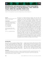
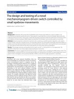
Synthesis of ZnO is performed in a quartz process tube
atabasepressureof130TorrasshowninFigure1.
The inductive heating synthesis system consists of a
13.56-MHz 600-W signal generator (MKS Instruments,
Andover, MA, USA), an adjustable auto-matching net-
work configured for an inductive load, a 40-mm-dia-
meter quartz process tube, and a process tube support
that has built-in cooling air vents. Two main compo-
nents of the synthesis system - the source and growth
substrates - are contained within the sealed quartz
chamber and f lushed with argon and oxygen at a ratio
of 99.67% to 0.33% at a total flow rate of 301 sccm. The
source is made up of solid zinc (99.999% purity; Strem
Chemicals, Inc., Newburyport, MA, USA) contained
within a p ure nickel heating chamber. The top side of
the nickel heating chamber is perforated to create an
orifice that acts as the Zn emission source. As RF power
is turned on, the induced magnetic field, by virtue of
the coils, produces (1) Joule and hysteresis heating - up
to nickel’ s Curie temperature of 358°C - in the nickel
chamber, and (2) inductively c oupled argon-oxygen
plasma. Zinc melts in the crucible and ionizes before
being ejected from the emission orifice in the form of a
Znplasmajet(Figure1b,c).ItisnotedthatnoZn
plasma is detected before the melting point of Zn (420°
C) is reached. The infrared image in Figure 1d shows
the uniformity of the temperature distribution of both
the exposed solid zinc and the supporting bottom plate
of the nickel heating chamber. As Zn ions leave the ori-
fice and are transported toward the fringe of the plasma,
they react with oxygen in the synthesis chamber to form
ZnO nanoparticles. These nanoparticles that are formed
in-flight supersaturate in the boundary layer o f the
growth substrate and deposit on the growth substrate
surface as ZnO nuclei, forming the foundation for sub-
sequent deposition of ZnO nanocrystalline films. The
source temperature attained by the nickel heating cham-
ber is 570°C, and the corresponding deposition tempera-
ture experienced by the growth substrate ranges from
160°C to 330°C.
We deposit ZnO on crystalline and amorphous growth
substrates including p-type silicon (100), mica (musco-
vite), fused quartz, c- and a-plane sapphire, borosilicate
glass,tin-dopedindiumoxide[ITO],andpolyimide
Pedersen et al. Nanoscale Research Letters 2011, 6:568
/>Page 2 of 12
(Kapton
®
, DuPont, Wilmington, DE, USA). The deposi-
tion rate (10 to 50 nm/min) is tightly controlled by a
closed-loop temperature control algorithm where the
output RF pow er is modulated by the source tempera-
ture. Based on experience, for a high rate of depositio n,
the RF power and plasma intensity - which is propor-
tional to the rate of change of the temperature of the
nickel heating chamber - must be relatively high, yet the
nickel heating chamber temperature is to be maintained
well below the boiling point of Zn, so that Zn droplets
donotformanddepositonthesubstrateasmetallic
zinc. This is achieved by maintaining the temperature of
the nickel heating chamber using a saw-toothed tem-
perature profile to attenuate the power periodically. The
controller RF output is pulsed to high power to main-
tain the appropriate nickel heating chamber temperature
Figure 1 ZnO nanoc rystalline film synt hesis system. Thermal plasma chemical vapor deposition system for depositing ZnO nanocrystalline
thin films which consists of a 13.56-MHz RF generator and a matching network, induction coil, zinc source (nickel heating chamber), and
substrate holder. (a) The synthesis chamber showing the position of the nickel heating chamber in relation to the induction coil. (b) When RF is
activated, the nickel heating chamber is inductively heated by Joule heating and by the inductively coupled argon/oxygen plasma. Molten zinc
is bombarded by high-energy argon, producing zinc ions that are ejected from the emission orifice. Subsequently, zinc vapor reacts with oxygen
to form ZnO, which deposits on the growth substrate. (c) Anatomy of the synthesis setup showing the location of the solid zinc disc that is
enclosed within a nickel heating chamber and the formation of a plasma jet. (d) Infrared image of an exposed nickel chamber showing uniform
temperature distribution across both nickel and zinc.
Pedersen et al. Nanoscale Research Letters 2011, 6:568
/>Page 3 of 12
rate increase. As an upper temperature limit is reached,
RF power is automatically reduced allowing the nickel
heating chamber to cool to a predetermined tempera-
ture. Further pulses can be programmed until the zinc
source is completely depleted. At the end of the deposi-
tion run, oxygen gas is switched off, and the system is
allowed to cool down to room temperature under only
Ar gas flow at the original flow rate.
Post-process film treatment and characterization
The surface morphology, film thickness, and crystal
dimensions of the synthesized ZnO nanocrystalline films
are characterized by scanning electron microscopy
[SEM] on a Zeiss Ultra 55 (Carl Zeiss Microscopy, Pea-
body, MA, USA) that is equipped with a Schottky field
emission gun. Elemental analysis is conducted u sing an
Oxford energy dispersive X-ray probe. Film crystallinity
is investigated using an X-ray diffractometer (Bruker D8
ADVANCE, Bruker AXS Inc., Madison, WI, USA) with
Cu-Ka radiation (l = 1.54178 Å) and a scann ing range
of 2θ between 24° and 100°. Electrical conductivity mea-
surement is conducted using a four-point probe, and
transmittance of the as-deposited film is measured using
aLambdaUV-Visspectrophotometer (PerkinElmer,
Inc., Waltham, MA, USA) with an integrating sphere.
The spectra are collected in the 200- to 800-nm spectral
range. Thermal annealing of samples is performed in a
tube furnace (MTI GSL-1100X, MTI Cor poration, Rich-
mond, CA, USA) at 300 sccm of argon flow at tempera-
tures ranging from 750°C to 950°C for 1 h.
Results and discussion
Properties of as-deposited ZnO film
At a constant argon-to-oxygen (99.67% to 0.33%) ratio
and a constant total flow rate (301 sccm), the morpholo-
gical and dimensional properties of the ZnO nanocrys-
talline thin films are found to be dependent on factors
including source temperature profile, deposition dura-
tion above the melting point of zinc (420°C), substrate
type and temperature, and thermal annealing tempera-
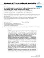
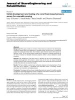
tures. Figure 2 shows the optical image and SEM images
(top view and ed ge-on view) of a typical ZnO film
deposited on a p-type silicon (100) using a saw-toothed
symmetric heating profile (Figure 3), where the rates of
heating and cooling are identical. As shown, the ZnO
film deposited on t he p-type silico n (100) surface
appears to be highly uniform.
Influence of source temperature profile and growth
duration
We find clear evidence in the experimental data that
correlates the total duration of the Zn source heated at
and above the melting temperature of zinc (420°C) in
the heating chamber to the as-deposited film
thicknesses, grain sizes, and grain structures. SEM
images of ZnO deposited from a nickel heating chamber
subjected to saw-toothed temperature profile up to 570°
C show a strong positive linear relationship between the
heating durations above 420°C and the film thicknesses,
as shown in Figures 3 and 4.
As the number of saw-tooth (’ pulse’ )andthetotal
synthesis duration above 420°C increase, the nominal
thicknesses of the films increase proportionately from
25 nm (1 pu lse, 135 s, Figure 3a) to 70 nm (3 pulses,
290s,Figure3b),and110nm(5pulses,445s,Figure
3c) at a growth rate of 16.7 nm/min. We also investi-
gated the influence of the resident ti me that the source
temperature stays at the peak temperature (570°C) on
film thickness. We compare two samples, Figure 3a, d,
where each has an identical saw-toothed heating profile.
The sample in Figure 3a has 1 s of resident time at 570°
C, while that of Figure 3d has 5 s of resident time at
570°C. Our results show that there is no significant dif-
ference in t he thicknesses b etween these two samples,
and the differences are within the range of errors - the
sample in Figure 3a has a nominal thickness of 25 nm,
while the sample in Figure 3d has a nominal thickness
of 22 nm . As shown, there are no noticeable differences
in the thicknesses despite the fact that the sample in
Figure 3d has four more seconds at the peak tempera-
ture. This shows that the total duration the source tem-
perature stays above 420°C, instead of at the peak
temperature of 570°C, plays a more critical role in influ-
encing the thicknesses of the films. Furthermore, when
comparing Figures 3 d and e, the effect of the duration
the source stays above 420°C beco mes more obvious -
longer synthesis time above 420° C leads to thickening of
the film (to 57 nm) a s shown in Figure 3e, the sample
which is exposed to 70 s longer than the sample in Fig-
ure 3d. It is evident that film thickness is predominantly
influenced by the heating duration at or above the melt-
ing point of zinc and, to a minimal extent, by changes
in the resident time at the peak temperature. The evi-
dence indicates that heating to just above 420°C is suffi-
cient to allow d eposition to occur in the argon-plasma
environment. The grain sizes also appear to increase
from an average grain diameter of 44 nm to 75 nm as
synthesis duration increases from 135 s to 445 s.
Influence of substrate type and substrate temperature
We have deposited ZnO nanocrystalline films on various
substrates including crystalline p-Si (100), c-plane sap-
phire, and a-plane sa pphire; amorphous fused quartz;
borosilicate glass; muscovite; gold; titanium; and polyi-
mide (Kapton
®
,DuPont,Wilmington,DE,USA).Figure
5 shows ZnO nanocrystalline films as deposited on four
ceramic and metallic substrates at substrate tempera-
tures of 330°C. The morphologies of ZnO films
Pedersen et al. Nanoscale Research Letters 2011, 6:568
/>Page 4 of 12
deposited appear t o be largely deposition surface-inde-
pendent for these substrates as the substrate materials
remain chemically and structurally stable at the growth
conditions and process temperature of 330°C. As shown
in Figure 5a, b, c, d, f ilm coverage o n the ceramic and
metallic substrates appears to be substrate-independent:
the films are continuous with no observed porosity.
Close examination of the films’ cross sections under
SEM reveal no evidence of epitaxial growth of ZnO on
any of these substrates and i n particular, crystalline a-
plane sapphire, which has the closest lattice match with
the c-plane of ZnO among all these substrates.
Figure 2 Optical and SEM images of ZnO film deposited on p-type Si(100).(a) ZnO nanocrystalline thin film as-deposited on p-type Si(100).
(b) SEM image (top view) and (c) SEM image (edge-on view) of ZnO nanocrystalline thin film showing uniformity and nonporous nature of the
film.
Pedersen et al. Nanoscale Research Letters 2011, 6:568
/>Page 5 of 12
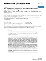
Figure 3 SEM images of ZnO films deposited using different source temperature profiles.(a1-e1) SEMs (top view), (a2-e2) SEMs (edge-on
view), and (a3-e3) source temperature profiles of ZnO nanocrystalline films deposited with saw-toothed temperature profiles that have resident
times of (a3) 135 s, (b3) 290 s, and (c3) 445 s above the melting point of zinc (420°C). The corresponding nominal thicknesses are (a2) 25 nm,
(b2) 70 nm, and (c2) 108 nm. (d) and (e) show the SEM images of ZnO films deposited using saw-toothed temperature profile similar to (a) but
with longer times - (d3) 5 s and (e3) 75 s - at the peak temperature of 570°C. The thicknesses of films hence deposited are (d2) 22 nm and (e2)
57 nm. Scale bar = 100 nm.
Pedersen et al. Nanoscale Research Letters 2011, 6:568
/>Page 6 of 12
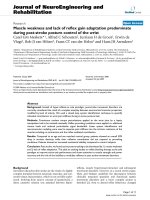
Figure 4 Relationships between film thickness, grain diameter, and deposition time. At a source temperature at or above 420°C, the ZnO
film thickness scales linearly with deposition time at a growth rate of 16.7 nm/min. Grain diameter also increases as deposition duration
increases.
Figure 5 Morphologies of ZnO films deposited on ceramic and metal substrates. The morphologies of ZnO films deposited on (a) p-type
Si(100), (b) muscovite, (c) gold, and (d) titanium at a substrate temperature of 330°C.
Pedersen et al. Nanoscale Research Letters 2011, 6:568
/>Page 7 of 12
Using an extended structu ral zone model proposed by
Mahieu et al. [37], the growth of ZnO film at a homolo-
gous temperature of 0.27 (at 330°C) follows a surface
diffusion-limited Volmer-Weber island growth model.
At this homologous temperature, ZnO nuclei that form
initially will grow into small grains with faceted struc-
tures due to self-surface diffusion of adparticles on the
underlying nuclei and grains. The anisotropic growth
rates of different crystallographic planes also dictate the
morphology of the grain structures. In the case of ZnO
grains, (002) plane has the lowest surface energy, and
hence, the growth rate of a ZnO grain is highest in the
direction perpendicular to the (002) plane [2,28,38].
Faceting of the ZnO grain is terminated by the planes of
the slowest crystallographic growth rate, which as indi-
catedbyFigure5,isthe(103)plane.Thisisconfirmed
by Figure 6 which shows the normalized X-ray diffracto-
graphs of ZnO films deposited on p-type Si(100) and c-
plane Al
2
O
3
, and fused quartz to be (002) plane-domi-
nated. Each of these films demonstrates a strong prefer-
ential orientation in the (002) plane direction. The next
dominant growth is in the direction perpendicular to
the (103) planes. The ratios of the relative intensity
peaks of (002)/(103) planes for all substrates are consis-
tently between 4 to approximately 7. SEM shows the
presence of (103) peaks to be largely attributed to the
terminating face, (103) plane, of the ZnO crystal. Peaks
attributed to (100), (101), and (102) are also present but
are small compared to the (002) peak.
For ZnO film deposition on polyimide, the substrate
temperature was controlled at 160°C, the lowest deposi-
tion achievable with this system. ZnO films deposited
on polyimide at 160°C appear to be conformal, as
shown in Figure 7a, b, yet contain microcracks and or
voids as observed under the SEM. The as-deposited
ZnO is conductive enough that SEM imaging can be
achieved without an additional conductive coating.
Energy dispersive X-ray spectroscopy confirms the pre-
sence of ZnO on polyimide in Figure 7c. The micro-
cracks and voids on as-deposited ZnO films are
attributed to a large thermal mismatch between ZnO (5
to 8 × 10
-6
/°C) and the underlying polyimide substrate
(35to40×10
-6
/°C). During the temperature ramp-up
phase, the polyimide substrate continues to expand
while ZnO is being deposited. This imposes a biaxial
tensile stress on the ZnO once a continuous ZnO film
has formed. As a result, as subsequent ZnO is being
deposited, the underlying ZnO continues to be subjected
to more tension from t he polyimide substrate until the
Figure 6 XRD of ZnO films deposited on ceramic substrates.
Normalized XRD of ZnO films deposited on (a ) p-type Si(100), (b)c-
plane sapphire, and (c) fused quartz at substrate temperature of
330°C.
Figure 7 SEM and EDX images of ZnO film deposited on
polymer.(a, b) SEM images of ZnO nanocrystalline film deposited
on polyimide (Kapton
®
) and (c) EDX of the ZnO film.
Pedersen et al. Nanoscale Research Letters 2011, 6:568
/>Page 8 of 12
tension is released by the formation of micr ocracks and
voids. The dimensional expansion reaches its maxi mum
value at the highest deposition temperature of 160°C. It
is hypothesiz ed that during the subsequent cooling
down stage, some of these cracks are closed due to a
larger shrinkage of the polyimide vis-a-vis the ZnO film.
Influence of thermal annealing
Thermal annealing in pure argon environment at tem-
peratures ranging up to 950°C is performed to elucidate
the effect of heat treatment in the absence of oxygen on
the grain morphologies and dimensionalitie s of ZnO
grains. Five cleaved spec imens of 200-nm-thick ZnO
films deposited on one p-type Si (100) wafer are annealed
for 90 min at various temperatures ranging from 750°C
to 950°C in a tube furnace supp lied with 300 sccm argon
at 130 Torr. SEM image (Figure 8) shows definitive mor-
phological changes that a re correlated to annealing tem-
peratures. Annealing at 750°C (0.46 T
m
)resultsinthe
growth of ZnO grains into larger grains with greater defi-
nition at the grain boundaries. At 800°C (0.48 T
m
),
restructuring of the grain texture produces conspicuous
(002) facets along with increased grain si zes and lower
grain density. As annealing temperature increases from
800°C to 900°C (0.52 T
m
), the increasing thermal energy
input causes further surface texture restructuring due to
grain boundary diffusion and bulk diffusion. This in turn
accelerates grain growth in the direction perpendicular to
the(002)plane-theZnOplanewiththelowestsurface
energy - and produces columnar ZnO grains that con-
tinuetoelongatealongthec-axis. Accompanying this
change is the noticeable growth in the direction parallel
to the surface of the substrate, i.e., in direction normal to
(100) planes. During grain growth, the larger grains are
formed by consuming smaller adjacent grains, which low-
ers the gra in density. The columnar Zn O crystals would
act as seeds for the seeded growth of nanorods as tem-
perature is further increased to 950°C (0.54 T
m
). SEM
images show that at 950°C, nascent nanorods form on
the aligned ZnO nanocrystals. At the same time, it is also
observed that the grain den sity continues to decrease
from 900°C to 950°C. This is likely due to the increased
bulk diffusion that provides for the growth of the
nanorods.
Optical properties
Figure 9 shows the optical properties of ZnO nanocrys-
talline films deposited on borosilicate glass substrates
and fused quartz. Figure 9a shows the optical transmit-
tance spectra of 200-nm-thick ZnO deposited under
identical process conditions on 25 samples of borosili-
cate squares (25.4 mm × 25.4 mm). The optical trans-
mittance spectra are measured in the wavelength range
Figure 8 SEM of ZnO films annealed in pure argon at
temperatures from 750°C to 950°C. Annealed samples from films
of initially identical morphology and average grain sizes show an
increasing restructuring of film texture with higher annealing
temperatures. (a) As-deposited ZnO film and ZnO films annealed at
(b) 750°C, (c) 800°C, (d) 850°C, (e) 900°C, and (f) 950°C. Scale bar =
100 nm.
Pedersen et al. Nanoscale Research Letters 2011, 6:568
/>Page 9 of 12
of l = 200 nm to 800 nm. The optical characteristics of
these samples show that the system is producing films
of consistent quality, thickness, and uniformity. The
high repeatability and deposition consistency of our pro-
cess minimizes run-to-run variation in terms of film
thickness and optical quality. Figure 9b shows the UV-
Vis spectrum of a ZnO film at two thicknesses, 20 nm
and 200 nm, deposited on fused quartz. At both thick-
nesses, sharp UV absorption edges at around 375 nm
are observed, which corresponds to an optical bandgap
energy, E, of approximately 3.26 eV according Equations
1 and 2 [39,40]:
E =
¯
hω −
α
(
ω
)
·
¯
hω
B
1
/
n
(1)
α
(
ω
)
=
2.303log
10
1
T
d
(2)
where E is the op tical bandgap, ħω is the photon
energy in eV, a(ω) is the absorption coefficient, ω is the
angular frequency, B is a constant between 10
5
and 10
6
cm
-1
, T is the transmittance, d is the fil m thickness, and
n is an exponential value = 1/2 [39]. The optical band-
gap energy for o ur films is closest to films deposited by
spray pyrolysis (3.26 eV) [41] and close to films depos-
ited by other methods such as CVD (3.19 to 3.23 eV)
[42] and pulsed laser deposit ion (3.26 eV) [43] and (3.1
eV) [44]. As shown in Figure 9b and the inset, ZnO
films at 20 nm and 200 nm exhibit high transmittance
in the visible range; however, the transmittance below
375 nm depends largely on the film thickness - thinner
films appear to be more transmissive, while thicker films
are less. Figure 9c, d shows the grain morphologies of
the 20-nm- and 200-nm-thick ZnO films, respectively.
The average grain sizes correspond to 25 nm and 100
nm, respectively, for the 20-nm and 200-nm films.
Finally, for the 200-nm-thick ZnO film, the four-point
Figure 9 Optical properties and grain structure of 20-nm- and 200-nm-thick ZnO films.(a) Optical transmittance of 25 samples of 200-nm-
thick ZnO film deposited on borosilicate glass slides. (b) Optical transmittance of 20-nm- and 200-nm-thick ZnO films deposited on 1.6-mm-thick
fused quartz wafers. (inset) Clockwise from top: 1, 000-nm-, 200-nm-, and 20-nm-thick ZnO films on fused quartz. SEM images of (c) 20-nm- and
(d) 200-nm-thick ZnO films deposited on fused quartz.
Pedersen et al. Nanoscale Research Letters 2011, 6:568
/>Page 10 of 12
probe measurement shows a conductivity of up to 910
S/m, indicating the ZnO film to be highly conductive.
Conclusions
We have successfully demonstrated a direct, catalyst-free
synthesis method of depositing conformal nanocrystal-
line ZnO films on crystalline and amorphous substrates
using a fast thermal plasma CVD process that is pre-
ceded by inductive heating. SEM ind icates that the ZnO
films deposited on ceramic and metal substrates at 330°
C are highly conformal with evenly distributed grain
sizes and a preferential growth direction along the c-
axis. ZnO films deposited at 160°C on polyimide are
conformal; however, due to a large thermal mismatch
between the f ilm and t he substrate, stress-induced por-
osity is observed. Such porosity is expected to be
reduced with a lower substrate temperature. Optical
measurements of 20-nm- and 200-nm-thick ZnO films
show a high optical transmittance at spectra 375 nm
and above, which correspond s to the optical bandgap of
ZnO. Thermal annealing of ZnO films at temperatures
ranging from 750°C to 950°C causes restructuring of the
grain. As annealing temperature increases, grain bound-
ary diffusion and bulk diffusion cause restructuring of
ZnO grains into ZnO nanorods.
Abbreviations
CVD: chemical vapor deposition; EDX: energy dispersive X-ray; ITO: tin-doped
indium oxide; SEM: scanning electron microscopy; TCO: transparent
conducting oxides; UV-Vis: ultraviolet-visible light; XRD: X-ray diffraction; ZnO:
zinc oxide.
Acknowledgements
The authors thank the following people: Dr. Andrew Ichimura for his
assistance with X-ray diffraction and UV-Vis spectrophotometry, and for his
fruitful discussions; Tom Franco and Richard Moore for the help in designing
the machine mechanical fixtures used in the experiments; Curtis Hilger for
his work on the implementation and tuning of the control system; and Mark
Brunson for a portion of the data collection work. Acknowledgment is made
to the Donors of the American Chemical Society Petroleum Research Fund
for partial support of this research under grant no. 49524-UNI 10.
Authors’ contributions
JDP and KST built the synthesis system and instrumented a closed-loop
temperature control. JDP and HJE carried out the experiments and data
collection. KST and JDP interpreted the results together. KST performed data
analyses and prepared the manuscript.
Competing interests
The authors declare that they have no competing interests.
Received: 14 September 2011 Accepted: 31 October 2011
Published: 31 October 2011
References
1. Look DC: Recent advances in ZnO materials and devices. Mater Sci Eng
2001, B80:383-387.
2. Wu J, Xue D: Progress of science and technology of ZnO as advanced
material. Sci Adv Mat 2011, 3:127-149.
3. Karber E, Raadik T, Dedova T, Krustok J, Mere A, Mikli V, Krunks M:
Photoluminescence of spray pyrolysis deposited ZnO nanorods.
Nanoscale Res Lett 2011, 6:359.
4. Yan C, Liu J, Liu F, Wu J, Gao K, Xue D: Tube formation in nanoscale
materials. Nanoscale Res Lett 2008, 3:473-480.
5. Norton DP, Heo YW, Ivill MP, Pearton SJ, Chisholm MF, Steiner T: ZnO:
growth, doping and processing. Mater Today 2004, 7:34-40.
6. Hutson AR: Hall effect studies of doped zinc oxide single crystals. Phys
Rev 1957, 108:222-230.
7. Sze SM: Physics of Semiconductor Devices. New York: Wiley; 1989.
8. Tsukazaki A, Ohtomo A, Onuma T, Ohtani M, Makino T, Sumiya M, Ohtani K,
Chichibu SF, Fuke S, Segawa Y, Ohno H, Koinuma H, Kawasaki M: Repeated
temperature modulation epitaxy for p-type doping and light-emitting
diode based on ZnO. Nat Mater 2004, 4:42-46.
9. Look DC, Reynolds DC, Litton CW, Jones RL, Eason DB, Cantwell G:
Characterization of homoepitaxial p-type ZnO grown by molecular
beam epitaxy. Appl Phys Lett 2002, 81:1830-1832.
10. Masuda S, Kitamura K, Okumura Y, Miyatake S, Tabata H, Kawai T:
Transparent thin film transistors using ZnO as an active channel layer
and their electrical properties. J Appl Phys 2003, 93:1624-1630.
11. Ong BS, Li C, Li Y, Wu Y, Loutfy R: Stable, solution-processed, high-
mobility ZnO thin-film transistors. J Am Chem Soc 2007, 129:2750-2751.
12. Fay S, Feitknecht L, Schlüchter R, Kroll U, Vallat-Sauvain E, Shah A: Rough
ZnO layers by LP-CVD process and their effect in improving
performances of amorphous and microcrystalline silicon solar cells. Sol
Energ Mater Sol Cell 2006, 90:2960-2967.
13. Fay S, Feitknecht L, Schlüchter R, Kroll U, Vallat-Sauvain E, Shah A:
Comparison of dye-sensitized ZnO and TiO
2
solar cells: studies of charge
transport and carrier lifetime. J Phys Chem C 2007, 111:1035-1041.
14. Tang ZK, Wong GKL, Yu P, Kawasaki M, Ohtomo A, Koinuma H, Segawa Y:
Room-temperature ultraviolet laser emission from self-assembled ZnO
microcrystallite thin films. App Phys Lett 1998, 72:3270-3272.
15. Yu SF, Yuen C, Lau SP, Wang YG, Lee HW, Tay BK: Ultraviolet amplified
spontaneous emission from zinc oxide ridge waveguides on silicon
substrate. App Phys Lett 2003, 83:4288-4290.
16. Yeh PH, Zhou L, Wang ZL: Schottky-gated probe-free ZnO nanowire
biosensor. Adv Mater 2009, 21:4975-4978.
17. Barankin MD, Gonzalez E II, Ladwig AM, Hicks RF: Plasma-enhanced
chemical vapor deposition of zinc oxide at atmospheric pressure and
low temperature. Sol Energ Mater Sol Cell 2007, 91:924-930.
18. Cheng AJ, Tzeng Y, Zhou Y, Park M, Wu TH, Shannon C, Wang D, Lee W:
Thermal chemical vapor deposition growth of zinc oxide nanostructures
for dye-sensitized solar cell fabrication. Appl Phys Lett 2008, 92:092113.
19. Carcia PF, McLean RS, Reilly MH, Nunes G Jr: Transparent ZnO thin-film
transistor fabricated by rf magnetron sputtering. Appl Phys Lett 2003,
82:1117-1119.
20. Tanusevskia A, Georgieva V: Optical and electrical properties of
nanocrystal zinc oxide films prepared by dc magnetron sputtering at
different sputtering pressures. Appl Surf Sci 2010, 256:5056-5060.
21. Kappertz O, Drese R, Wuttig M: Correlation between structure, stress and
deposition parameters in direct current sputtered zinc oxide films. J Vac
Sci Technol A 2002, 20:2084-2095.
22. Tan ST, Chen BJ, Sun XW, Fan WJ: Blueshift of optical band gap in ZnO
thin films grown by metal-organic chemical-vapor deposition. J Appl
Phys 2005, 98:013505/1-013505/5.
23. Subramanian M, Tanemura M, Hihara T, Ganesan V, Soga T, Jimbo T:
Magnetic anisotropy in nanocrystalline Co-doped ZnO thin films. Chem
Phys Lett 2010, 487:97-100.
24. Xu Z, He H, Sun L, Y Jin Y, Zhao B, Ye Z: Localized exciton emission from
ZnO nanocrystalline films. J Appl Phys 2010, 107:052524/1-052524/5.
25. Chen SJ, Liu YC, Ma JG, Zhao DX, Zhi ZZ, Lu YM, Zhang JY, Shen D Z,
Fan XW: High-quality ZnO thin films prepared by two-step thermal
oxidation of the metallic Zn. J Crys Gro 2002, 240:467-472.
26. Li SZ, Zhou SM, Liu HX, Hang Y, Xia CT, Xu J, Gu SL, Zhang R: Low-
temperature hydrothermal growth of oriented [0001] ZnO film. Mat Lett
2006, 61:30-33.
27. Zhang Y, Lin B, Sun X, Fu Z: Temperature-dependent photoluminescence
of nanocrystalline ZnO thin films grown on Si (100) substrates by the
sol-gel
process. Appl Phys Lett 2005, 86:131910/1-131910/3.
28. Yan C, Xue D: Electroless deposition of aligned ZnO taper-tubes in a
strong acidic medium. Electrochem Comm 2007, 9:1247-1251.
29. Shigeta M, Murphy AB: Thermal plasmas for nanofabrication. J Phys D:
Appl Phys 2011, 44:1-16.
Pedersen et al. Nanoscale Research Letters 2011, 6:568
/>Page 11 of 12
30. Luo L, Sosnowchik B, Lin L: Room temperature fast synthesis of zinc
oxide nanowires by inductive heating. Appl Phys Lett 2007, 90:093101.
31. Sosnowchik B, Lin L: Rapid synthesis of carbon nanotubes via inductive
heating. Appl Phys Lett 2006, 89:193112.
32. Guo JY, Gitzhofer F, Boulos MI: Induction plasma synthesis of ultrafine SiC
powders from silicon and CH
4
. J Mat Sci 1995, 30:5589-5599.
33. Boulos MI, Fauchais B, Pfender E: Thermal Plasmas: Fundamentals and
Applications. New York: Springer; 1994.
34. Groenen R, Loffler J, Sommeling PM, Lindend JL, Hamersa EAG,
Schropp REI, van de Sandena MCM: Surface textured ZnO films for thin
film solar cell applications by expanding thermal plasma CVD. Thin Solid
Films 2001, 392:226-230.
35. Robbins JJ, Harvey J, Leaf J, Fry C, Wolden CA: Transport phenomena in
high performance nanocrystalline ZnO:Ga films deposited by plasma-
enhanced chemical vapor deposition. Thin Solid Films 2005, 473:35-40.
36. Cebulla R, Wendt R, Ellmer K: Al-doped zinc oxide films deposited by
simultaneous rf and dc excitation of a magnetron plasma: relationships
between plasma parameters and structural and electrical film properties.
J Appl Phys 1998, 83:1087-1095.
37. Mahieu R, Ghekiere P, Depla D, De Gryse R: Biaxial alignment in sputter
deposited thin films. Thin Solid Films 2006, 515:1229-1249.
38. Wang ZL: Zinc oxide nanostructures: growth, properties and
applications. J Phys: Condens Matter 2004, 16:829-858.
39. Natsume Y, Sakata H: Zinc oxide films prepared by sol-gel spin-coating.
Thin Solid Films 2000, 372:30-36.
40. Davis EA, Mott NF: Conductivity, optical absorption and
photoconductivity in amorphous semiconductors. Philos Mag 1970,
22:903-922.
41. Aranovich J, Ortiz A, Bube RH: Optical and electrical properties of ZnO
films prepared by spray pyrolysis for solar cell applications. J Vac Sci Tech
1979, 16:994-1003.
42. Natsume Y, Sakata H, Hirayama T: Low-temperature electrical conductivity
and optical absorption edge of ZnO films prepared by chemical vapour
deposition. Phys Stat Sol A 1995, 148:485-495.
43. Craciun V, Elders J, Gardeniers JGE, Boyd IW: Characteristics of high quality
ZnO thin films deposited by pulsed laser deposition. Appl Phys Lett 1994,
65:2963-2965.
44. Narasimha KL, Pai SP, Palkar VR, Pinto R: High quality zinc oxide films by
pulsed laser ablation. Thin Solid Films 1997, 295:104-106.
doi:10.1186/1556-276X-6-568
Cite this article as: Pedersen et al.: Direct Synthesis and Characte rization
of Optically Transparent Conformal Zinc Oxide Nanocrystalline Thin
Films by Rapid Thermal Plasma CVD. Nanoscale Research Letters 2011 6:568.
Submit your manuscript to a
journal and benefi t from:
7 Convenient online submission
7 Rigorous peer review
7 Immediate publication on acceptance
7 Open access: articles freely available online
7 High visibility within the fi eld
7 Retaining the copyright to your article
Submit your next manuscript at 7 springeropen.com
Pedersen et al. Nanoscale Research Letters 2011, 6:568
/>Page 12 of 12