Báo cáo hóa học: " Zenithal alignment of liquid crystal on homeotropic polyimide film irradiated by ion beam" pdf
Bạn đang xem bản rút gọn của tài liệu. Xem và tải ngay bản đầy đủ của tài liệu tại đây (202.18 KB, 12 trang )
This Provisional PDF corresponds to the article as it appeared upon acceptance. Fully formatted
PDF and full text (HTML) versions will be made available soon.
Zenithal alignment of liquid crystal on homeotropic polyimide film irradiated by
ion beam
Nanoscale Research Letters 2012, 7:63 doi:10.1186/1556-276X-7-63
Yoonseuk Choi ()
Tae-Hoon Yoon ()
Jin Hyuk Kwon ()
Jonghoong Yi ()
Jin Seog Gwag ()
ISSN 1556-276X
Article type Nano Express
Submission date 7 September 2011
Acceptance date 5 January 2012
Publication date 5 January 2012
Article URL />This peer-reviewed article was published immediately upon acceptance. It can be downloaded,
printed and distributed freely for any purposes (see copyright notice below).
Articles in Nanoscale Research Letters are listed in PubMed and archived at PubMed Central.
For information about publishing your research in Nanoscale Research Letters go to
/>For information about other SpringerOpen publications go to
Nanoscale Research Letters
© 2012 Choi et al. ; licensee Springer.
This is an open access article distributed under the terms of the Creative Commons Attribution License ( />which permits unrestricted use, distribution, and reproduction in any medium, provided the original work is properly cited.
1
Zenithal alignment of liquid crystal on homeotropic polyimide film
irradiated by ion beam
Yoonseuk Choi
1
, Tae-Hoon Yoon
2
, Jin Hyuk Kwon
3
, Jonghoong Yi
3
, and Jin Seog Gwag*
3
1
Department of Electronics, Hanbat National University, Daejeon, 305-719, South Korea
2
Department of Electronics Engineering, Pusan National University, Pusan, 609-735, South
Korea
3
Department of Physics, Yeungnam University, 214-1 Dae-dong, Gyeongsan 712-749,
South Korea
*Corresponding author:
Email addresses:
YC:
THY:
JHK:
JY:
JSG:
Abstract
We investigate the pretilt characteristics of a nematic liquid crystal [LC] in terms of ion
beam exposure conditions on the homeotropic polyimide alignment layer. The pretilt angle
of LCs in the case of high-energy ion beam treatment was decreased considerably almost
the same to that of the homogenous alignment layer though we used homeotropic
polyimide film at first. Increasing irradiating energy, we could control the pretilt from 90°
to 1° with several steps. We believe that this is because the side chain with hydrophobicity
in the used polyimide is broken by ion beam exposure. To confirm it, contact angle
measurement was carried out. With this result, we can easily control the LC pretilt in the
pixel with appropriate exposure conditions which is critical to achieve excellent
electrooptic characteristics and good image quality.
Introduction
In practical applications of liquid crystals [LCs], the study of the LC alignment near the
surface including in-plane and out-of-plane directions is crucial. Various alignment
techniques have been introduced to create physical/chemical anisotropy on the surface of
the alignment layer [1-11]. The most representative skill used in industry is the rubbing
method which has high productivity. However, since rubbing is a contact method, it often
produces a fine scratch on the alignment layer during the process, and it results in several
disadvantages, such as the rubbing mura at a dark level of liquid crystal displays [LCDs].
To overcome such problems, various alternative non-contact methods are suggested for
high-resolution LCDs such as photo-alignment technique with ultraviolet [UV] light and
2
ion beam technique [1, 7]. The polarized UV irradiation technique has many merits such as
a clear image without the mura at a black level and an easy creation of multi-domain in a
pixel. However, it also has a problem such as an image-sticking issue due to a low-surface
anchoring strength.
Since the extremely collimated ion beam to confirm a high linear motion can induce an
excellent anisotropy on the polyimide surface by selective destruction of π-bonding which
plays an important role in the alignment of LCs, it could be a good option of non-contact
surface modification method [2, 10]. Also, this method is relatively free of the
image-sticking problem since it generates a strong anchoring strength like the rubbing
method. Therefore, we can conclude that an appropriate LC pretilt control technique
considering LCD modes is essential to obtain better electrooptical characteristics of LCDs
and to develop new LC device applications.
In this paper, we investigate the pretilt characteristics of a nematic LC in terms of ion
beam irradiation conditions using homeotropic polyimide alignment layer. The
modification of LC pretilt with different ion beam exposure parameters was studied
experimentally. As a result, we successfully changed the pretilt angle from 90° to 1° with
several sub-steps.
Experimental details
The glass substrates coated with indium tin oxide whose size is 30 mm × 20 mm × 0.7 mm
are spin-coated with the polyimide AL-00010, which is provided by Japan Synthetic
Rubber Corporation (Minato-ku, Tokyo, Japan). It subsequently was prebaked at 80°C for 3
min to remove the solvent and cured at 230°C for 30 min for polymerization on a hot plate.
Figure 1 shows the chemical structure of the polyimide AL-00010. In general, the pretilt
angle of LCs is determined mainly by the chemical property of the side chain in the
polyimide. Since the side chain in the AL-00010 has hydrophobicity with a nonpolar
molecule, we can easily know that it may align LCs vertically.
After coating and baking, this homeotropic polyimide film was bombarded by an argon ion
beam to change the LC aligning properties of the surface. In this experiment, various ion
beam exposure conditions such as the irradiation energy, exposure angle, exposure time,
and current density are modulated to examine how the surface property is changed
according to them. As an ion source, a cold hollow cathode [CHC] is used to yield a highly
collimated ion beam. In order to collimate the ion beam, two perforated grids are used as
electro-focusing lenses. The CHC represents a separate cooled chamber which is equipped
with a magnetic system and is connected to a discharge chamber through an orifice. Argon
gas feeding into the ion source is carried out through the CHC only.
In order to investigate the pretilt angle of treated polyimide surfaces, we had fabricated
several LC cells by using the substrates with different ion beam exposure conditions. The
cell was filled with a nematic LC (MLC-6610 from Merck KGaA, Darmstadt, Germany)
3
with negative dielectric anisotropy, and the cell gap was maintained by 12-µm glass spacers.
The LC injection was carried out at room temperature. The pretilt angle was measured by
the extended crystal rotation method which can measure a wider range of the pretilt
[12-13].
Results and discussion
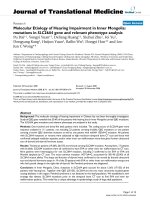
As shown in Figure 2, we can see that the pretilt angle of the LC is aligned almost
horizontally in some ion beam conditions such that the ion beam energy is higher than 150
eV when exposure angle, exposure time, and ion beam current density are 30°, 20 s, and 25
µA, respectively. This may indicate that the side chain with hydrophobicity in the
polyimide AL-00010 is destroyed or broken off by ion beam particles, and eventually, the
average polarity of the used surface has changed. In general, the remaining portion of the
side chain on the polyimide surface determines the LC pretilt on average.
To confirm our speculation about the change of the surface property of AL-00010 after ion
beam exposure, we had measured the surface contact angle. The contact angle is described
as the angle between the solid surface and the tangent line of liquid at the solid-liquid-vapor
interface when the liquid is in a thermal equilibrium state on the solid. The equilibrium
state of the contact angle which represents minimum total interfacial energy is obtained
when the vector sum of the horizontal force components among the solid-liquid,
liquid-vapor, and solid-vapor interface is zero. This method has a merit which can measure
the surface property without any surface damage. Generally, the wetting of liquid at the
interface is a result to reduce the interfacial energy. The spreading parameter S related to
interfacial tension can be defined by
sv sl lv
S
γ γ γ
= − −
(1)
Here,
sv
γ
is tension between solid and vapor,
sl
γ
is tension between solid and liquid, and
lv
γ
is tension between liquid and vapor. In Equation 1, when
sl lv sv
0 ( )
S
γ γ γ
≥ + ≤ , the
solid is wetted by the liquid entirely, and then, it is called complete wetting. If
sl lv sv
0 ( )
S
γ γ γ
< + > , then the solid prefers the vapor to the liquid; however, since the
liquid is heavier than the vapor, the liquid is placed under the vapor, and then, the solid is
wetted partially by the liquid. Thus, it is called partial wetting. Young's equation describing
the relation of the three interfacial tensions in equilibrium state is written as
lv sv sl
cos
γ θ γ γ
= −
, (2)
where
θ
is the contact angle. As known in Equation 2, when the liquid is water with
chemical polarity, the lower the contact angle is, the higher the surface energy and the
hydrophilic property are. Meanwhile, the higher the contact angle is, the lower the surface
energy and the hydrophilic property are.
In this measurement, we used distilled water having chemical polarity as a liquid. The ion
beam-treated polyimide AL-00010 substrate of which the ion beam conditions are ion beam
energy of 300 eV, ion beam current density of 50 µA/cm
2
, exposure angle of 30°, and
exposure time of 30 s was used as a sample. The ion beam condition is enough to modify
4
the surface as shown in Figure 2. As a comparison, the sample with untreated polyimide
AL-00010 substrate was examined.
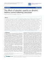
The contact angle at static mode was reduced seriously after ion beam treatment as shown
Figure 3a,b,c. Figure 3a is a droplet image taken on a sample before ion beam treatment.
On the other hand, Figure 3b,c shows droplet images taken parallel and perpendicular to the
ion beam-irradiated direction for the ion beam-treated sample, respectively. This result
supports obviously the analysis that the side chain with hydrophobicity in the polyimide
broke off or was destroyed by the ion beam as expected in the sharp decrease of the LC
pretilt (see Figure 2). In an additional experiment, we measured the dynamic contact angle
of this sample. The dynamic contact angle is the contact angle before slipping down the
liquid on the substrate when we tilt the sample slowly and informs us macroscopically of
the relative information about the surface roughness. Generally, if the angle difference
between the advancing angle and receding angle is larger, then the surface is rougher.
Figure 3d,e,f shows that the angle difference is small for the direction perpendicular to the
ion beam exposure. Figure 3d is taken before treatment, and Figure 3e,f images are taken in
the case of parallel and perpendicular ion beam irradiation, respectively. This means that
the roughness of the surface in the case of parallel irradiation is bigger than that that of the
perpendicular irradiation case. Note that this matches well to other ion beam treatment
results [14]. Consequently, we verify what the LC pretilt change causes in ion beam
exposure from the contact angle method.
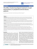
Based on the relationship between the ion beam exposure condition and the pretilt angle
indicated in Figure 2, to enlarge the margin of LC pretilt control by ion beam irradiation,
the ion beam conditions for our ion beam equipment were optimized and were 70 eV, 20
µA/cm
2
, and 10°. In our ion beam equipment, ion beam irradiation with an ion beam energy
under 70 eV generated a large fluctuation of beam current. Figure 4 shows the change of
the LC pretilt according to exposure time at the optimized condition. As you see, we can
know that the LC pretilt margin is enlarged extensively compared with Figure 2. We would
get a larger margin of the LC pretilt if we could have a better one.
Conclusion
In summary, we investigated the LC pretilt property according to the ion beam exposure
conditions on a homeotropic LC alignment. The LCs on a higher energy ion beam-treated
surface is aligned almost homogenously. We assumed that it may be caused by the breaking
of the side chain with hydrophobic property in the used polyimide by ion beam exposure. It
was confirmed from the result of the contact angle measurement. LC pretilt which may
create new LCD applications with excellent electrooptic characteristics and good image
quality can be controlled by an ion beam condition with proper ion beam parameters.
Competing interests
The authors declare that they have no competing interests.
5
Authors' contributions
YC carried out the sample preparation and measurement and drafted the manuscript. THY
and JHK participated in the design of the study and performed the analysis. JY carried out
the ion beam exposure and measurement. JSG conceived the study, participated in its
design and coordination, and drafted the manuscript. All authors read and approved the
final manuscript.
Acknowledgments
This work was supported by a grant from the National Research Foundation of Korea
(NRF) funded by the Korean government (Grant No. 2011-0002447) and a grant from the
Human Resources Development Program (R&D Workforce Cultivation Track for Solar
Cell Materials and Processes) of Korea Institute of Energy Technology Evaluation and
Planning (KETEP) (No. 20114010100580) funded by the Korean government's Ministry of
Knowledge Economy.
References
[1] Schadt M, Seiberle H, Schuster A: Optical patterning of multi-domain liquid-crystal
displays with wide viewing angles. Nature 1996, 381:212-215.
[2] Chaudhari P, Lacey J, Doyle J, Galligan E, Lien SCA, Callegari A, Hougham G, Lang
ND, Andry PS, John R, Yang KH, Lu M, Cai C, Speidell J, Purushothaman S, Ritsko J,
Samant M, Stöhr J, Nakagawa Y, Katoh Y, Saitoh Y, Sakai K, Satoh H, Odahara S, Nakano
H, Nakagaki J, Shiota Y: Atomic-beam alignment of inorganic materials for
liquid-crystal displays. Nature (London) 2001, 411:56-59.
[3] Janning JL: Thin film surface orientation for liquid crystals. Appl Phys Lett 1972,
21:173-175.
[4] Nakamura M, Ura M: Alignment of nematic liquid crystals on ruled grating
surfaces. J Appl Phys 1972, 52:210-218.
[5] Gibbons WM, Shannon PJ, Sun ST, Swetlin BJ: Surface-mediated alignment of
nematic liquid crystals with polarized laser light. Nature 1991, 351:49-50.
[6] Kawatsuki N, Yamamoto T, Ono H: Photoinduced alignment control of photoreactive
side-chain polymer liquid crystal by linearly polarized ultraviolet light. Appl Phys Lett
1999, 74:935-937.
[7] Kim J-H, Kumar S, Lee S-D: Alignment of liquid crystals on polyimide films
exposed to ultraviolet light. Phys Rev E 1998, 57:5644-5650.
[8] Gwag JS, Jhun CG, Kim JC, Yoon T-H, Lee G-D, Cho SJ: Alignment of liquid crystal
on a polyimide surface exposed to an Ar ion beam. J Appl Phys 2004, 96:257-260.
[9] Berreman DW: Solid surface shape and the alignment of an adjacent nematic liquid
crystal. Phys Rev Lett 1972, 28:1683-1686.
[10] Gwag JS, Fukuda J, Yoneya M, Yokoyama H: In-plane bistable nematic liquid
crystal devices based on nanoimprinted surface relief. Appl Phys Lett 2007, 91:073504.
[11] Gwag JS, Yoneya M, Yokoyama H, Kim J-H: Surface nematic bistability at
nanoimprinted topography. Appl Phys Lett 2008, 92:153110.
[12] Gwag JS, Lee SH, Park K-H, Park WS, Han K-W, Jhun CG, Yoon T-H, Kim JC, Song
6
D-M, Shin D-M: Simple method for measuring the high pretilt angle of nematic liquid
crystals. J Appl Phys 2004, 93:4936-4938.
[13] Scheffer TJ, Nehring J: Accurate determination of liquid‐
‐‐
‐crystal tilt bias angles. J
Appl Phys 1977, 48:1783-1792.
[14] Son PK, Choi S-W: Preferred pre-tilt direction of liquid crystal molecules on
rubbed polyimide surfaces. J Kor Phys Soc 2010, 57:207-209.
7
Figure 1. The chemical structure of the polyimide AL-00010 used as the LC alignment
layer.
Figure 2. LC pretilt angle depending on ion beam exposure conditions. (a) LC pretilt
angle as the function of ion beam energy, (b) LC pretilt angle as the function of exposure
time, (c) LC pretilt angle as the function of exposure angle, and (d) LC pretilt angle as the
function of ion beam current density.
Figure 3. The contact angle of droplet on a sample before and after ion beam
treatment. For static mode, (a) the droplet image on the sample before ion beam treatment,
(b) the droplet image taken parallel to the ion beam-irradiated direction after ion beam
treatment, and (c) the droplet image taken perpendicular to the ion beam-irradiated
direction after ion beam treatment. For dynamic mode, (d), (e), and (f) show that the angle
difference is smaller for the direction perpendicular to the ion beam exposure.
Figure 4. LC pretilt angle according to exposure time at optimized ion beam
parameters.
Figure 1
0 50 100 150 200 250 300
0
20
40
60
80
100
P
retilt angle [degree]
Ion
beam energy [eV]
Ex
posure angle : 30
o
Exposure time : 20 s
Exposure current density : 25
oA/cm
2
(a)
0 10 20 30 40 50 60
0
20
40
60
80
100
(b
)
Ex
posure angle : 30
o
Exposure energy : 100 eV
Exposure current density : 25 oA/cm
2
P
retilt angle [degree]
Ex
posure time [s]
0 10 20 30 40 50 60
0
20
40
60
80
100
(c)
Ex
posure energy : 100 eV
Exposure time : 20 (s)
Exposure current density : 25
oA/cm
2
P
retilt angle [degree]
Ex
posure angle [degree]
0 10 20 30 40 50 60
0
20
40
60
80
100
(d
)
Ex
posure angle : 30
o
Exposure energy : 100 eV
Exposure time : 20 (s)
P
retilt angle [degree]
Ion
beam current density [oA]
Figure 2
102.1fl
68.5fl
69fl
(a)
(b)
(c)
103fl
68.5fl
74.5fl
39.2fl
42.9fl
74.7fl
(d)
(e)
(f)
Figure 3
0 10 20 30 40 50 60
0
20
40
60
80
100
P
retilt angle [degree]
Ex
posure time [s]
E
xposure energy : 70 eV
Exposure current density : 20 oA/cm
2
Exposure angle : 10
o
Figure 4