Báo cáo hóa học: "Nanopatterning on silicon surface using atomic force microscopy with diamond-like carbon (DLC)-coated Si probe" pptx
Bạn đang xem bản rút gọn của tài liệu. Xem và tải ngay bản đầy đủ của tài liệu tại đây (1.1 MB, 7 trang )
NANO EXPRESS Open Access
Nanopatterning on silicon surface using atomic
force microscopy with diamond-like carbon
(DLC)-coated Si probe
Xiaohong Jiang
1
, Guoyun Wu
1
, Jingfang Zhou
2
, Shujie Wang
1
, Ampere A Tseng
3
and Zuliang Du
1*
Abstract
Atomic force microscope (AFM) equipped with diamond-like carbon (DLC)-coated Si probe has been used for
scratch nanolithography on Si surfaces. The effect of scratch direction, applied tip force, scratch speed, and number
of scratches on the size of the scratched geometry has been investigated. The size of the groove differs with
scratch direction, which increases with the applied tip force and number of scratches but decreases slightly with
scratch speed. Complex nanostructures of arrays of parallel lines and square arrays are further fabricated uniformly
and precisely on Si substrates at relatively high scratch speed. DLC-coated Si probe has the potential to be an
alternative in AFM-based scratch nanofabrication on hard surfaces.
Introduction
Nanolithography is crucial to realize a size below 100
nm for nanoelectronic devices and high density record-
ing systems [1,2] . Apart from conventional, expensive
optical and electron beam lithography [1,2], scanning
probe microscopy (SPM), especially scanning tunneling
microcopy (STM) and atomic force microscopy (AFM)-
based nanofabrication technique have been intensively
studied. To date, several SPM-based nanolithography
techniques have been developed including local oxida-
tion of the surfaces of silicon and metals [3-5], dip-pen
method [6,7], thermal-mechanical writing [2,8], and
mechanical/electrochemical modification of a material’s
surface [9-11]. In recent years, although the uncertainty
(drift, hysteresis, creep for AFM) will limit its applica-
tion in nanostructure fabrication at large scale,
AFM-based scratch nanolithography has emerged as a
promising technique for nanofabrication because of its
simplicity, versatility, reliability, and operation in ambi-
ent conditions [3-12]. It is also expected to fabricate
nanostructure at a large scale with combination of
nano-imprint system. AFM scratching technique takes
advantage of the ability of moving a probe over a sample
surface in a controllable way. By controlling the applied
normal force (F
n
) between a probe and a sample surface,
trenches or grooves with depths from a few to tens of a
nanometer and widths from tens to hundreds of
nanometers can be fabricated on both soft and hard
substrates, involving polymer [13], silicon [14], oxides
[15], magnetic metals, and semiconductor materials [16].
This technique thus has the potential to benefit the fab-
rication of nanoelectronic devices such as nanodots [17],
nanowires [18], and single electron devices [1]. For
example, the patterning on sapphire substrate by
AFM-based nanolithography can reduce the dislocation
density for III-nitride based light emitting diodes [19-21].
Previous reports in AFM-based scratch nanolithogra-
phy has focused on making different nanodevices and
nanosystems, in which a Si or Si
3
N
4
tip with a typic al
radius of less than 20 nm was used, and the scratch was
processed mainly on flexible polymer substrates
[1,11,18]. To scratch on a hard Si surface, an AFM tip
with high wear resistance has to be used. Recently, SPM
scratch nanopatterning on a Si surface was investigated
by several groups [22-24], the tips, however, were coated
exclusively with diamond, which is costly. According to
our knowledge, AFM scratching using diamond-like car-
bon (DLC)-coated probe has not been reported. DLC
film is an amorphous film, and its surface is very
smooth. Because of its high hardness and high elastic
modulus, low coefficient of friction, wear and good
tribological property, it is suitable as a wear-resistant
* Correspondence:
1
Key Laboratory of Special Functional Materials of Ministry of Education,
Henan University, Kaifeng 475004, People’s Republic of China
Full list of author information is available at the end of the article
Jiang et al. Nanoscale Research Letters 2011, 6:518
/>© 2011 Jiang et al; lic ensee Springer. This is an Open Access article distr ibuted under the terms of the Creative Commons Attributi on
License ( s/by/2.0), which permits unrestricted use, distribution, and reproduction in any me dium,
provided the original w ork is properly cited.
coating [25]. From the preparation point of view, the
cost for DLC films is much cheaper than that of dia-
mond, and the co mmercial DLC-coated tip can easily be
obtained. In the present study, we explored the potential
of this economic probe in fabricating nanopatterns on
hard silicon surface. The scratch characteristics were
investigated and correlated to the scratch parameters.
More complex nanostructures such as line and square
arrays were further fabricated using a DLC-coated tip
on a silicon substrate.
Experiment
The silicon surface selected was polished single crystal
p-type Si(100). Before scratching, the sample was
cleaned thoroughly by sonication in acetone and etha-
nol, respectively and then rinsed with deionized water.
The centerline average roughness (R
a
)andthemaxi-
mum roughness (R
max
) of the samp le surfaces calculated
from 2.0 × 2.0 μm
2
topographic AFM images were less
than 0.14 and 1.19 nm, respectively. Scratch experiments
and AFM imaging were carried out in an ambient con-
dition using a vector scan method. Firstly, the sample
surface approached the commercial DLC tip i n the Z-
direction until the tip contacting with the sample sur-
face under a preset load. Then, the feedback loop was
closed and the PZT actuator drove the sample moving
in t he x-andy-direction, and nano grooves were
scratched under the constant set normal force, scan
speed, and repeated times for scratch [26]. Finally, the
AFM tip was lifted to the original height, and the
grooves’ structure was characterized b y AFM after the
nanofabrication. The DLC-coated S i probe for scratch-
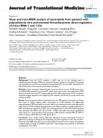
ing has been sharpened into a triangular pyramid. A
scanning electron microscope (SEM) image was shown
in Figure 1a. T he thickness of the DLC layer is approxi-
mately 15 nm, and the tip radius of curvature is about
15 nm. The spring constant of the tip is 48 N/m, indi-
cating the tip has a high wear resistance, which aims to
keep the sharpness of the tip unchange d during scratch-
ing. The AFM images of the surfaces before and after
Figure 1 SEM and AFM images. (a) SEM image of DLC-coated triangular pyramid tip, together with the schematic of the scratch direction. (b)
The AFM images of the typical grooves scratched at 10 μN of tip force, 1 μm/s of speed. (c) The cross-section profiles of the grooves at the
position as indicated by the line. (d) Schematic of oblique cutting, inclination angle θ defined as the angle between the directions of scratching
and cutting face.
Jiang et al. Nanoscale Research Letters 2011, 6:518
/>Page 2 of 7
scratch were measured in conta ct mode using a Si
3
N
4
tip, which has a low spring constant of about 0.02 N/m
to avoid additional damage to the sample surface.
Results and discussion
Two scratch directions, forward and backward, were
selected to scratch the Si surface. As illustrated in Figure
1a, forward scratch has the sharp cutting edge along the
scratch direction, while the backward scratch uses the
flat cutting edge facing the scratch direction. The influ-
ence of scratch direction on the size of the scratched
geometry was initially investigated. The AFM images of
the typical grooves in both directions are given in Figure
1b, along with the corresponding cross-section profiles
of the grooves as shown in Figure 1c, where the scratch
was performed at 1 μm/s of the scratching speed and 10
μN of the applied normal force. The cross-section pro-
files are V-shaped in both scratch conditions. However,
the depth of the groove generated in the forward scratch
is clearl y deeper than that in the backward direction, as
seen in Figure 1c. This could be attributed to the
sharpness of the tip in the forward direction, where the
effective normal force was higher and a deeper groove
was thus produced [27]. A similar phenomenon was
obs erved in the investigation of A FM scratch on Si sur-
face with diamond-coated Si tip [22-24,28]. The pyrami-
dal tip has three scratching faces as shown in Figure 1d,
the inclination angle, θ, is defined as the angle between
the directions of scratching and cutting face. In the ca se
of the backward direction, the tip scratch face is perpen-
dicular to the scratch direction, i.e., the inclination
angle, θ, equals 90°, which satisfies the requirement to
become orthogonal cutting. The protuberances are cre-
ated evenly along two sides of the grooves. On the other
hand, if scratching is in the forward direction, the
scratching face is composed of two inclination angles, i.
e., one is -30° and the other is 30°. As a result, the pro-
tuberances are squeezed evenly onto the two sides of
the groove scratched. Since the 30° or -30° inclination
angle provides much more favorable stress states to
squeeze the materials onto the two sides as compared
with that of the 90° inclination angle, the protuberances
created in forward scratching is more or larger than that
of the backward direction.
The relationship between the groove size and the
scratch parameters including applied normal force,
number of scratch and scratch speed were further
investigated in forward scratch. Ten cross-section pro-
files were randomly selected in different locations
along the groove. The line width of the groove is
defined by the full width at half maximum. The depth
(d)andwidth(W
f
) of the groove were calculated from
the measurement of the groove profiles at the ten
points and were then averaged [28]. The AFM images
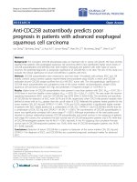
of the scratched grooves generated under different nor-
mal forces are given in Figure 2a, b at both low-force
regime (from approximately 0 to 10 μN) and high-
forceregime(fromapproximately10to20μN),
respectively. The scratch was performed in the forward
direction at one scratch cycle, and the scratch speed
was fixed at 1 μm/s. The protuberances were observed
along the banks near the groove mouth, which was
caused mainly by plastic deformation during the
scratch and was difficult to remove. The scratched
groove size as a function of the applied normal force is
showninFigure2c.Withtheincreaseoftheapplied
normal force from 1 to 20 μN, the size of the grooves
was increased from 0.68 to 3.35 nm in depth a nd from
21.59 to 26.19 nm in width. In the low-force regime,
the groove depth and width increased linearly when
the normal force ranging from 1 to 10 μN, while in
the high-force regime from 12 to 20 μN, the groove
depth and width increased slowly and the saturation
characteristics occurred. Prioli et. al. reported similar
phenomena on aluminum film by diamond tip [29].
This phenomenon indicating that the effective normal
force markedly decreases when the contact area of the
tip with the surface becomes larger at a force above 10
μN because of the nonlinear increments of the tip
cross-section. Roughly speaking, the depth of the
groove that can be scratched is proportional to the
magnitude of the tip stresses (in which tip is acting as
a cutting tool) that is the tip force divided by the lat-
eral (horizontal) cross-section area of the tip. As
shown in Figure 1a, the cross-section area increases
much faster than the depth. Consequently, the non-
linear behavior of the relationship between groove
dimension and tip force results from the nonlinear
increments of the cross-section area of the tip.
Experiments have been c onducted to study the effect
of changing the scratching speed on the shapes of
scratched grooves. The AFM images of the scratched
grooves at different scratch speeds are given in Figure
3a, and the corresponding depth and width o f the
grooves as a function of scratch speed is shown in
Figure 3b. When the scratch speed increased from 0.1
to 10 μm/s, the depth decreased very slightly from 3.09
to 2.73 nm, indicating that the scratch speed did not
have much influence on scratched depth. On the other
hand, the width decreased sharply at low speed range
and then reduced slowly at scratch speed higher than 1
μm/s, which fits a negative logarithm equation. However,
the width changed from 26.36 to 22.9 nm and thus the
total reduction was not significant, implying that AFM-
based scratch nanolithography with a DLC-coated tip can
be carried out at high scratch speed.
Jiang et al. Nanoscale Research Letters 2011, 6:518
/>Page 3 of 7
Figure 3 AF M images of scratched grooves at different scratch speeds. (a) The AFM images of the scratches at 10 μN of applied force in
the forward scratch. (b) Correlation of the size of the scratched grooves with the scratch speed.
Figure 2 AFM images of the grooves. (a-b) The AFM images of the grooves scratched at 1 μm/s of scratch speed under different applied
forces in the forward scratch. (c) The size of the scratched grooves as a function of the applied normal force.
Jiang et al. Nanoscale Research Letters 2011, 6:518
/>Page 4 of 7
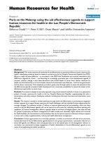
Repeated scratches were also conducted in scratching
experiments to study the effects of the number of the
scratch or scan cycle on the size of the scratched geo-
metry. It is expected that multiple or repeating scratch
cycles along the same scratch path can enlarge the
groove size. Figure 4a shows the AFM images of the
grooves a t different numb er of scratches. It was
observed that small wear debris accumulating along the
bank near the groove mouth during scratch. The corre-
sponding depth and width of the grooves as a function
of the number of scratches are given in Figure 4b. It
was found that both depth and width increased linearly
with the increase in the number of scratches. The size
of the width increased faster than that of the depth.
According to Ogino’s report, the depth of the groove
increased linearly, while the width of the groove was
unchanged. The linear increase of the depth was attribu-
ted to the layer-by-layer removal mechanism during
scratching.
Tseng et al. found that d and W
f
of the grooves
increased with the number of scratch cycles (N
o
) follow-
ing a power-law relationship [23]:
d
(
N
o
)
= M
1
(
N
o
)
n
1
(1)
and
W
f
(N
o
)=M
2
(N
o
)
n
2
,
(2)
where M
i
and n
i
are the multiple scratch coefficient
and multiple scratch exponent, respectively. As the d and
W
f
data for multiple scratches on a Si(100) is illustrated
in Figure 4b, the correlation values of M
1
, M
2
, n
1
,andn
2
can be found to be 1.93, 20.26, 0.80, and 0.35 nm,
respectively. The associated coefficient of determination
(R
2
)is0.99ford and 0.88 for W
f
, which indicate that the
power-law correlation fitting the depth data perfectly,
and there is a 12% deviation for the width data.
Using a DLC-coated tip, more complex nanostruc-
tures including arrays of parallel lines and square
arrays were fabricated by AFM scratch on Si substrate.
Figure 5 shows the nanopatterns generated at 10 μNof
the tip force, 1 μm/s of the scratch speed, and four
scratches. For the arrays of parallel lines with an area
of 1 × 1 μm
2
, the depth of the groove is about 2 nm
with a pitch of 90 nm. As for the square arrays
scratchedonanareaof1×1μm
2
, the depth of the
groove is about 10 nm, and the dimension of a square
area is 100 × 110 nm
2
with a pitch of 70 nm. The line
arrays and square arrays in microscale were fabricated
precisely and uniformly on a Si surface, indicating that
AFM-based scratch lithography with a DLC-coated tip
could be used to fabricate complex nanostructures on
a hard silicon surface.
Conclusion
In the present study, we explored the potential of the
DLC-coated tip used as a cutting tool in AFM-based
scratch nanolithography on a silicon surface. The
scratched geometry w as correlated to the scratch para-
meters, such as t he scratch d irection, applied tip force,
scratch speed, and number of scratches. Uniform nano-
patterns of line arrays and square arrays were further
fabricated. This work provides an insight for fabricating
nanopatterns on a hard material precisely and rapidly
using an inexpensive AFM tip.
Figure 4 Eff ects of the number of scratch or scan cycle. (a) The AFM image s of the scratches at 10 μNofappliedforceand1μm/s of
scratch speed in the forward scratch. (b) Correlation of d and W
f
data with numbers of scratching cycle (N
o
) for Si(100).
Jiang et al. Nanoscale Research Letters 2011, 6:518
/>Page 5 of 7
Acknowledgements
This work was supported by the National Natural Science Foundation of
China (nos. 10874040, 90306010, and 20803018) and the Cultivation Fund of
the Key Scientific and Technical Innovation Project, Ministry of Education of
China (no. 708062).
Author details
1
Key Laboratory of Special Functional Materials of Ministry of Education,
Henan University, Kaifeng 475004, People’s Republic of China
2
Ian Wark
Research Institute, University of South Australia, Mawson Lakes SA 5095,
Australia
3
School of Engineering of Matter, Transport and Energy, Arizona
State University, Tempe, AZ 85287-6106, USA
Authors’ contributions
XHJ and WGY are the primary authors and conceived of the study, carried
out the experiments, characterization, acquisition of data, analysis and
interpretation of data, drafting of the manuscript and revisions. And they
contribute equally to this paper. JFZ and WSJ participated in language
modification. AT participated in analysis and interpretation of data. ZLD is
the principal investigator.
Competing interests
The authors declare that they have no competing interests.
Received: 4 July 2011 Accepted: 2 September 2011
Published: 2 September 2011
References
1. Bitton L, Frydman A: Controllable room-temperature metallic quantum
dot. Appl Phys Lett 2006, 88:113113.
2. Binnig G, Despont M, Drechsler U, Häberle W, Lutwyche M, Vettiger P, et al:
Ultrahigh-density atomic force microscopy data storage with erase
capability. Appl Phys Lett 1999, 74:1329-1331.
3. Bo XZ, Rokhinson Leonid P, Yin HZ, Tsui DC, Sturm JC: Silicon nanowire
transistors with a channel width of 4 nm fabricated by atomic force
microscope nanolithography. Appl Phys Lett 2002, 81:3263-3265.
4. Held R, Vancura T, Heinzel T, Ensslin K, Holland M, Wegscheider W:
Fabrication of ZnO thin film transistors by atomic force microscopy
nanolithography through zinc thin films. Appl Phys Lett 1998, 73:262-264.
5. Pellegrino L, Yanagisawa Y, Ishikawa M, Matsumoto T, Tanaka H, Kawai T:
Controlled fabrication of epitaxial (Fe, Mn)
3
O
4
artificial nanowire
structures and their electric and magnetic properties. Adv Mater 2006,
18:3099-3104.
6. Su M, Dravid VP: Direct patterning of modified oligonucleotides on
metals and insulators by dip-pen nanolithography. Appl Phys Lett 2002,
80:4434-4436.
7. Wang HT, Nafday OA, Haaheim JR, Tevaarwerk E, Amro NA, Sanedrin RG,
et al: Electrochemical AFM “dip-pen” nanolithography. Appl Phys Lett
2008, 93:143105.
8. Mamin HJ: Thermal writing using a heated atomic force microscope tip.
Appl Phys Lett 1996, 69:433-435.
9. Notargiacomo A, Foglietti V, Cianci E, Capellini G, Adami M, Faraci P:
Atomic force microscopy lithography as a nanodevice development
technique. Nanotechnology 1999, 10:458-463.
10. Li RW, Kanki T, Tohyama HA, Hirooka M, Tanaka H, Kawai T:
Nanopatterning of perovskite manganite thin films by atomic force
microscope lithography. Nanotechnology 2005, 16:28-31.
11. Gregor M, Plecenik A, Plecenik T, Tomasek M, Kus P, Micunek R, et al:
Preparation of variable-thickness MgB
2
thin film bridges by AFM
nanolithography. Physica C 2006, 435:82-86.
12. Ito T, Okazaki S: Pushing the limits of lithography. Nature 2000,
406:1027-1031.
13. Li LQ, Hirtz M, Wang WC, Du C, Fuchs H, Chi LF: Patterning of polymer
electrodes by nanoscratching. Adv Mater 2010, 22:1374-1378.
14. Santinacci L, Djenizian T, Hildebrand H, Ecoffey S, Mokdad H, Campanella T,
et al: Selective palladium electrochemical deposition onto AFM-
scratched silicon surfaces. Electrochimica Acta 2003, 48:3123-3130.
15. Lu G, Zhou XZ, Li H, Yin ZY, Li B, Huang L, et al: Nanolithography of
single-layer graphene oxide films by atomic force microscopy. Langmuir
2010, 26:6164-6166.
16. Versen M, Klehn B, Kunze U, Reuter D, Wieck AD: Nanoscale devices
fabricated by direct machining of GaAs with an atomic force
microscope. Ultramicroscopy 2000, 82:159-163.
17. Jung B, Jo W, Gwon MJ, Lee E, Kim DW: Scanning probe lithography for
fabrication of Ti metal nanodot arrays. Ultramicroscopy 2010, 110:737-740.
18. Chen YJ, Hsu JH, Lin HN: Fabrication of metal nanowires by atomic force
microscopy nanoscratching and lift-off process. Nanotechnology 2005,
16:1112-1115.
19. Ee YK, Biser J, Cao W, Chan HM, Vinci RP, Tansu N: Metalorganic vapor
phase epitaxy of III-Nitride light-emitting diodes on nano-patterned
AGOG sapphire substrate by abbreviated growth mode. IEEE J Selected
Topics in Quantum Electronics 2009, 15:1066-1072.
Figure 5 AFM images of generated nanopatterns. The AFM images of (a) the line arrays and (b) square arrays scratched at 10 μN of applied
force, 1 μm/s of scratch speed, and four scratches.
Jiang et al. Nanoscale Research Letters 2011, 6:518
/>Page 6 of 7
20. Ee YK, Li XH, Biser J, Cao WJ, Chan HM, Vinci RP, et al: Abbreviated MOVPE
nucleation of III-nitride light-emitting diodes on nano-patterned
sapphire. J Crys Growth 2010, 312:1311-1315.
21. Li YF, You S, Zhu MW, Zhao L, Hou WT, Detchprohm T, et al: Defect-
reduced green GaInN/GaN light-emitting diode on nanopatterned
sapphire. Appl Phys Lett 2011, 98:151102.
22. Ogino T, Nishimura S, Shirakashi J: Scratch nanolithography on Si surface
using scanning probe microscopy: influence of scanning parameters on
groove size. Jpn J Appl Phys 2008, 47:712-714.
23. Tseng AA: A comparison study of scratch and wear properties using
atomic force microscopy. Appl Surf Sci 2010, 256:4246-4252.
24. Arda Gozen B, Burak Ozdoganlar O: A rotating-tip-based mechanical
nano-manufacturing process: nanomilling. Nanoscale Res Lett 2010,
5:1403-1407.
25. Huang SJ, Jeng YR, Liu KF: Sliding wear characteristics of the diamond-
like carbon films on alloy substrates. Wear 2007, 263:1266-1273.
26. Malekian M, Park SS, Strathearn D, Mostofa Md G, Jun MBG: Atomic force
microscope probe-based nanometric scribing. J Micromech Microeng
2010, 20:115016.
27. Yan YD, Sun T, Dong S: Study on effects of tip geometry on AFM
nanoscratching tests. Wear 2007, 262:477-483.
28. Tseng AA, Shirakashi J, Nishimura S, Miyashita K, Notargiacomo A:
Scratching properties of nickel-iron thin film and silicon using atomic
force Microscopy. J Appl Phys 2009, 106:044314.
29. Fonseca Filho HD, Maurício MHP, Ponciano CR, Prioli R: Metal layer mask
patterning by force microscopy lithography. Mat Sci Eng B 2004,
112:194-199.
doi:10.1186/1556-276X-6-518
Cite this article as: Jiang et al.: Nanopatterning on silicon surface using
atomic force microscopy with diamond-like carbon (DLC)-coated Si
probe. Nanoscale Research Letters 2011 6:518.
Submit your manuscript to a
journal and benefi t from:
7 Convenient online submission
7 Rigorous peer review
7 Immediate publication on acceptance
7 Open access: articles freely available online
7 High visibility within the fi eld
7 Retaining the copyright to your article
Submit your next manuscript at 7 springeropen.com
Jiang et al. Nanoscale Research Letters 2011, 6:518
/>Page 7 of 7