Báo cáo hóa học: "DRO: domain-based route optimization scheme for nested mobile networks" pdf
Bạn đang xem bản rút gọn của tài liệu. Xem và tải ngay bản đầy đủ của tài liệu tại đây (792.2 KB, 19 trang )
RESEARCH Open Access
DRO: domain-based route optimization scheme
for nested mobile networks
Ming-Chin Chuang and Jeng-Farn Lee
*
Abstract
The network mobility (NEMO) basic support protocol is designed to support NEMO management, and to ensure
communication continuity between nodes in mobile networks. However, in nested mobile networks, NEMO suffers
from the pinball routing problem, which results in long packet transmission delays. To solve the problem, we
propose a domain-based route optimization (DRO) scheme that incorporates a domain-based network architecture
and ad hoc routing protocols for route optimization. DRO also improves the intra-domain handoff performance,
reduces the convergence time during route optimization, and avoids the out-of-sequence packet problem. A
detailed performance analysis and simulations were conducted to evaluate the scheme. The results demonstrate
that DRO outperforms existing mechanisms in terms of packet transmission delay (i.e., better route-optimization),
intra-domain handoff latency, convergence time, and packet tunneling overhead.
Keywords: network mobility (NEMO), route optimization, ad hoc routing protocol, hando ff
1. Introduction
Recently, vehicular networks have received a significant
amount of attention in the field of wireless mobile net-
working. On public methods of transportation, such as
taxies, trains, buses, and airplanes, many mobile network
nodes (MNNs) move together as a large-scale vehicular
network. In such environments, people can use mobile
devices for accessing services, such as VoIP, video con-
ferencing, web-browsing, and music downloading, any-
time-anywhere. With the emergence of vehicular
networks, users require seamless and efficient communi-
cations on the move. Therefore, developing a route opti-
mization scheme has beco me an important res earch
issue.
The network mobility (NEMO) basic support protocol
[1] was proposed by the Internet Engineering Task
Force to support NEMO management, and ensure com-
munication continuity for nodes in mobile networks. A
mobile network compr ises one or more mobile routers
(MRs) that provide access to the Internet. The MR
transmits packets to MNNs via the ingress interface,
and accesses the Internet/MRs through the egress inter-
face. It also substitutes for MNNs in the mobile network
by performing binding updates (BU) to the home agent
(HA) without additional registration such that NEMO
can reduce the si gnaling overhead. The main operations
of NEMO are exten ded from Mobile IPv6 (MIPv6) pro-
tocol [2], which uses bi-directional tunneling between
theMRandtheHAtopreservesessioncontinuity.
However, in nested mobile networks, NEMO suffers
from the pinball routing problem [3]. When the level of
nesting in a mobile network increases, the packets,
which have to pass through HAs at each level, must be
encapsulated many times, resulting in long packet trans-
mission delay and high tunneling overhead. Figure 1
illustrates the pinball routing problem in nested mobile
networks, where the packets are transmitted from the
correspondent node (CN) to MNN1. The data routing
path in NEMO is CN ® HA3 ® HA2 ® HA1 ® AR
® MR1 ® MR2 ® MR3 ® MNN1, which is inefficient.
Hence, there is a need fo r an efficient route optimiza-
tion scheme [4].
The NEMO routing protocol can be divided into (1)
inter-domain routing, which means the MNN and the
CN are in different nested mobile networks; and (2)
intra-domain routing, where the MNN and the CN are
inthesamenestedmobilenetwork.Mostapproaches
focus on the inter-domain routing problem and use a
hierarchical architecture to achieve route optimization.
* Correspondence:
Department of Computer Science and Information Engineering, National
Chung Cheng University, Chia-Yi, Taiwan
Chuang and Lee EURASIP Journal on Wireless Communications and Networking 2011, 2011:70
/>© 2011 Chuang and Lee; licensee Spri nger. This is an Open Access article distrib uted under the terms of the Creative Commons
Attribution Lic ense (http://creativec ommons.org/licenses/by/2.0), which permits unrestricted use, distribution, and rep roduction in
any medium, provided the original work is properly cited.
However, hierarchy-based schemes may suffer from the
non-optimal route problem when the CN and the MNN
are located in the same nested mobile network (i.e.,
intra-domain routing). Moreover, such schemes do not
cope with the handoff procedure well, resulting in long
convergence time in route optimization or communica-
tion disruption. Actually, the handoff procedure has a
substantial impact on the p erformance of route optimi-
zati on because it is implemented before route optimiza-
tion. If the handoff latency (HL) is long, then it disrupts
communications or causes long convergence time in
route optim ization. Therefore, we also consider the
handoff problem to reduce the latency in route optimi-
zation. Similar to the NEMO routing protocol, inter-
domain handoff means that the MR hands off to a dif-
ferent nested mobile network; while intra-domain hand-
off means the MR hands off within the same nested
mobile network. Hence, the proposed mechanism con-
siders route optimization for inter-domain and intra-
domain routing, and reduces the HL in both scenarios.
Although route optimization reduces the packet trans-
mission delay, it may suffer from the packet out-of-
sequence problem. Out-of-sequence packets degrade the
TCP performance by generating duplicate ACKs at the
receiver. Although, the MNN can receive the packet
successfully, the CN still decreases its sending rate via
fast recovery mechanism to avoid congestion. Eventually,
the out-of-sequence packets reduce the CN’ssending
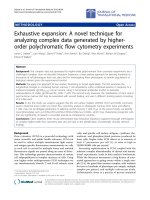
rate, which results in low network performance. Figure
2 illustrates the packet out-of-sequence problem in
inter-domain and intra-domain route optimization. In
this example, the CN sends a sequence of packets {P
1
,
P
2
, ,P
n
} to the MNN. The dotted lines represent the old
(non-optimal) path and the solid lines represent the new
(optimal) path. After the route optimization procedure,
the sequence of packets {P
i+1
,P
i+2
, ,P
n
}traversesthe
optimal path, but t he sequence of packets {P
1
, P
2
, ,P
i
}
traverses the non-optimal path. Consequently, the pack-
ets may arrive at the MNN out of sequence, which
would impact the network performance (e.g., TCP
applications).
In this article, we propose a domain-based route opti-
mization (DRO) scheme. The domain-based network
architecture incorporates the operations of ad hoc rout-
ing protocols for performing route optimization and
reduce HL. Moreover, we use a double buffer mechan-
ism in DRO to prevent the packet out-of-sequence pro-
blem during the route optim ization procedure. We
Figure 1 The pinball routing problem in a nested mobile network.
Chuang and Lee EURASIP Journal on Wireless Communications and Networking 2011, 2011:70
/>Page 2 of 19
compare DRO’s perform ance with that of existing route
optimization schemes via analysis and simulations. The
results demonstrate that DRO outperforms the com-
pared schemes in terms of packet transmission delay,
HL, convergence time, and packet tunneling overhead.
The remainder of this article is organized as follows.
Section 2 contains a review of related work. In Section
3, we describe the proposed DRO scheme. In Section 4,
we evaluate the scheme’s performance in terms of
packet delay (PD), HL, packet overhead during tunnel-
ing, and total cost (TC). Section 5 contains some con-
cluding remarks.
2. Related work
In this section, we discuss existing schemes for solving
the pinball routing problem, out-of-sequence problem,
and route optimization using the concepts of mobile ad
hoc networks (MANETs).
The reverse routing header [5] uses new extension
headers to inform the HAs of an MR in the nested
structure. However, this header modification needs to
be performed by each MR that an outgoing packet
passes through. Moreover, the modification and re-
computation overhead of the packet checksum or CRC
increases with the level of the nested mobile network.
The recursive binding update (RBU) [6] allows the HAs
to maintain the binding information for the care-of-
address (CoA) of the root mobile router (RMR). Conse-
quently, RBU can use the BU messages to find the opti-
mal route. However, RBU needs long convergence time
to find the optimal route when there are many handoff
events because the HAs need to repeat the RBU proce-
dure for each event. Calderon et al. [7] propose the
Mobile IPv6 route optimization scheme for NEMO
(MIRON) based on the protocol for carrying authentica-
tion for network access (PANA) [8] and the dynamic
host configuration protocol (DHCPv6) [9]. However,
MIRON needs to modify all MRs and visiting mobile
nodes (VMNs). Moreover, MIRON will not work well if
theVMNsdonothavePANAclientsoftware,orthe
MR does not have PANA client and server software.
SIP-NEMO [10] extends SIP to support NEMO s o that
the packets can be transmitted directly between the
MNN and the CN, but the scheme only applies to appli-
cations that use SIP. The route optimization using tree
information option (ROTIO) scheme [11] has a fast
CN
oAR nAR
MR
MNN
CN
RMR MR
MNN
oAR: old Access Router
nAR: new Access Router
MR: Mobile Router
CN: Correspondent Node
MNN: Mobile Network Node
RMR
:
R
oo
t M
ob
il
e
R
ou
t
e
r
MR
(a) (b)
{P
1
,P
2
, , P
n
}{P
1
,P
2
, , P
n
}
Handoff
{P
1
,P
2
, , P
i
}{P
1
,P
2
, , P
i
}{P
i+1
,P
i+2
, , P
n
}{P
i+1
,P
i+2
, , P
n
}
{P
1
,P
2
, ,P
i+1
,P
i+2
,P
i
, ,P
n
}
{P
1
,P
2
, ,P
i+1
,P
i+2
,P
i
, ,P
n
}
The path before route optimization
The path after route optimization
RMR
Figure 2 The packet out-of-sequence problem: (a) inter-domain route optimization; (b) intra-domain route optimization.
Chuang and Lee EURASIP Journal on Wireless Communications and Networking 2011, 2011:70
/>Page 3 of 19
convergence time during route optimization. However, if
an inter-domain handoff event occurs, the communica-
tion may be disconnected since ROTIO does not handle
inter-domain handoff well. Kuo and Ji [12] proposed an
enhanced hierarchical NEMO protocol called HRO+,
which reduces the PD in inter-domain and intra-domain
routing. In inter-domain routing, the CN sends the
packets to the RMR directly without passing through
any HA because the MR binds the NEMO prefix of
RMR to the CN. In intra-domain routing, each MR
records the routi ng information of sub-MRs. Therefore,
the MR can find an optimal path when the sender and
receiver belong to its sub-MR. However, HRO+ does
not consider inter-domain handoff and it also suffers
from the suboptimal routing problem in intra-domain
routing (i.e., the sender and the receiver do not have the
same parent MR). N-PMIPv6 [13] uses Proxy Mobile
IPv6 (PMIPv6) protocol [14] to reduce HL in a NEMO
environment, but it does not address the route optimi-
zation issue.
During the route optimization procedure, the MNN
may receive out-of-sequence packets, as shown in Figure
2. In this situation, receivers will transmit duplicate
ACKs so that the performance of TCP will be degraded.
Zheng et al. [15] and Tandjaoui et al. [16] anticipate the
arrival time of packets from the old link to adjust the
transmission time of packets from the new link. The
drawback of these schemes is that, since they are based
on prediction methods, they suffer from packet loss or
inaccurate time estimation when the network environ-
ment varies.
MANEMO integrates MANET and NEMO technolo-
gies to provide IP connectivity across nested mobile net-
works. Clausen et al. [17] used the optimized link state
routing (OLSR) protocol to support route optimization,
but the scheme does not consider the handoff situation
of the MR. McCarthy et al. [18,19] introduced the
MANEMO concept and identified two key solution
areas in the MANEMO problem domain, namely,
NEMO-Centric MANEMO (NCM) and MANET-Cen-
tric MANEMO (MCM). McCarthy et al. [20,21] and
Tsukad a and Ernst [22] bui lt testbeds for implementing
and experimenting with the MANEMO protocols.
Although their results show that MANEMO outper-
forms the traditional NEMO protocol, they only consid-
ered inter-domain route optimiza tion and measured the
packet transmission delay between the CN and the
MNN. They did not describe the route optimization
mechanism in detail or solve the mobility problem in
NEMO.
A MANET comprises a collection of mobile nodes
that form a temporary network without any infrastruc-
ture. Each mobile node in a MANET can act as a sender
and cooperate with other nodes and act as a relay in
multi-hop transmissions. Moreover, mobile nodes can
self-organize and maintain the routing information
through routing protocols. In general, the routing proto-
cols for MANETs can be classified as proactive routing
protocols [23] and on-demand routing protoco ls [24,25]
based on whether each node maintains the routing
tables or finds the route to destination before transmit-
ting data. These routing protoco ls find the optimal path
from the source to the destination based on certain
routing metrics. They also have mechanisms to deal
with dynamic topology changes because of node mobi-
lity or link failures.
The preliminary version of this study was published in
WCNC 2009 [26] based on ad hoc routing protocol for
nested mobile network. In this article, it contains signifi-
cant contributions not covered by the preliminary ver-
sion of this study as listed as follows:
(1) We discuss more related work in this journal
version.
(2) We describe the proposed scheme in detail such as
the intra-domain routing and the inter-domain hand off
procedures. Moreover, we propose the double buffer
mechanism to avoid the packet out-of-sequence pro-
blem. We also correct some flaws of the conference
version.
(3) In the preliminary version, we only use the numer-
ical analysis to evaluate the HL and the PD of intra-
domain and inter-domain handoff procedures. However,
in this version, we add detailed analytical models for
‘Convergence Time of Route Optimization during Inter-
Domain Handoff’, ‘Packet Overhead Ratio (POR)’, ‘TC’,
and ‘Discussion of Double Buffer Mechanism’.More-
over, we use NS-2 simulations to evaluate the perfor-
mance of DRO compared with existing mechanisms and
verify the analytical models.
3. The DRO scheme
Route optimization involves minimizing the packet
transmission delay between the sender and the receiver.
Although many hierarchy-based route optimization
schemes [11,12] support route optimization for inter-
domain routing, a non-optimal route is formed when
theCNandtheMNNarelocatedinthesamenested
mobile network (i.e., intra-domain routing). Moreover,
these schemes do not cope with the handoff procedure
well, resulting in a long convergence time during route
optimization or communication disruption. To resolve
these problems, we propose a novel NEMO support
protocol with a DRO scheme. The domain-based net-
work architecture incorporates the routing techniques of
MANETs for route optimization. We also use the archi-
tecture to reduce intra-domain HL and provide a fast
handoff scheme to achieve low inter-domain HL. In
addition, we use a double buffer mechanism to avoid
Chuang and Lee EURASIP Journal on Wireless Communications and Networking 2011, 2011:70
/>Page 4 of 19
the packet out-of-sequence problem during the route
optimization procedure.
3.1 MANET routing protocols
Our DRO scheme is based on MANET routing proto-
cols since these routing protocols find the optimal path
fromthesourcetothedestination.Moreover,theyalso
have mechanisms to deal with dynamic topology
changes because of node mobility or link failures.
Therefore, we use the protocols to find the shortest/
optimal path among MRs in nested mobile networks in
order to achieve route optimization. Most hierarchy-
based schemes do not adopt these routing protocols
because they use tree-based network architectures for
mobility management. In contrast, our domain-based
network architecture functions like a mesh network;
hence, it is compatible with all MANET routing
protocols.
3.2 Domain construction
The major differences between our domain-based
scheme and other hierarchy-based schemes are the net-
work construction and the MR address schemes. In
hierarchy-based schemes, the networks use a top-down
approach to form link relations between MRs for mobi-
lity management, resulting in a tree-based network
architecture, as shown in Figure 3a. Moreover, the des-
cendant MRs configure their CoAs from mobile node
prefix (MNP) of their parent-MRs (e.g., the MR3 config-
ures its address according to the prefix of the MR2). In
contrast, our domain-based network architecture is like
a mesh network, and the descendant MRs configure
their CoAs from MNP of the RMR (e.g., the MR3 con-
figures its address according to the prefix of the RMR),
resulting in forming a flat network topology (i.e., ad hoc
domain), as shown in Figure 3b. Moreover, the whole
MRs have the same network prefix, and thus they com-
municate with each other by ad hoc routing protocol.
In our domain-based network architecture, when an
MR moves in the mobi le network, it works as the RMR
in the domain if it receives an router advertisement
(RA) message from access router (AR). Moreover, the
new RMR configures its CoA according to the prefix of
the AR, binds its new CoA to the HA, inserts its prefix
in RA message, and then broadcasts the RA message.
However, if the MR receives an RA message from othe r
intermediate MRs (IMRs), it acts as an IMR, joins this
domain, generates its CoA based on the prefix of the
RMR, and rebroadcasts the RA message. Then, it finds
the shortest path to the RMR based on the routing pro-
tocol adopted by the mobile network and binds the CoA
of the RMR to its HA. In DRO, each MR sends two
kinds of BU messages: a local BU and a global BU. The
former is sent to the RMR and other MRs in the
domain, and the latter is for the HA and CN of the MR.
Finally, every MR follows the routing information
recorded in the network’s routing protocol so that the
network nodes can communicate via the optimal routes.
Figure 4 shows th e format of an RA message. W e
modified the fields highlighted in gray for our domain-
based network architect ure. The RA message works like
a “hello” message in our scheme, and the routing infor-
mation is included in the RA message. If the MR needs
to perform inter-domain hando ff, the ‘New CoA of
RMR’ and ‘Prefix of new RMR’ fields will be inserted in
the extended field. Moreover, to prevent a loop, we add
a field for the sequence number. The AR sends the RA
message periodically. It is noted that the RMR is capable
of deciding the domain size, and it inserts the rebroad-
cast limit into the RA message.(Theissueofthemost
suitable domain size is out of scope of this article.)
We use the following example to describe the advan-
tage of our domain-based network architecture. In hier-
archy-based schemes, the CoA of each sub-MR is based
on the prefix of its parent-MR, and every parent-MR is
responsible for recording the routing information of its
sub-MRs. Therefore, hierarchy-based schemes provide
shorter routes and reduce the packet transmission delay
than NEMO. However, they still suffer from the subop-
timal routing problem if the source and destination
MRs are in the same nested mobile network (i.e., intra-
domain routing), but they have different parent-MRs.
Figure 3a illustrates the inefficiency of intra-domain
routing in hierarchy-based schemes. The parent-MRs in
such schemes are only responsible for managing the
routing information of their sub-MRs. Hence, in the fig-
ure, MR3 forwards the packets for MR5 to its parent-
MR (i.e., MR2), since it only handles the routing to
MNN1 and has no routing information about MR5. The
packets are forwarded up the tree until the parent-MR
has the routing information for the destination MNN.
Therefore, if MNN1 wants to communicate with
MNN2, the routing path is: MNN1 ® MR3 ® MR2 ®
MR1 ® MR4 ® MR5 ® MNN2. However, there are
many shorter routing paths, e.g., MNN1 ® MR3 ®
MR7 ® MR5 ® MNN2 as shown in Figure 3b.
In addition, hierarchy-based schemes still do not cope
with intra-domain handoff well in a nested mobile net-
work. If an MR performs intra-domain handoff, then it
suffers from long HL since it needs to perform the local
duplicate address detection (DAD) procedure and gener-
ate a new CoA. Furthermore, the convergence time is
directly proportional to the HL. Therefore, hierarchy-
based schemes cannot handle the handoff procedure
efficiently, so there is a long convergence time during
route optimization. In our domain-based scheme, a net-
work domain consists of an RMR and a set of its des-
cendant MRs. The descendant MRs (i.e., MR2-MR7 in
Chuang and Lee EURASIP Journal on Wireless Communications and Networking 2011, 2011:70
/>Page 5 of 19
Figure 3b; A:A:A::/56-A:A:F::/56) create their CoAs from
the MNP of the RMR (i.e., MR1 in Figure 3b; A:A::/48),
rather than the prefix of their parent-MR as in hierar-
chy-based schemes. The RMR acts as the domain root
and manages all descendant MRs in the network
domain and every descendant MR records a default
routing path to the RMR. It is noted that the RMR will
notify the s ub-MR to generate a new sub-prefix if the
sub-prefix of the sub-MR is not unique in the domain.
When an MR moves within the same nested mobile net-
work (i.e., intra-domain handoff), it only updates its
RMR with the routing information and it does not need
to change its address. Our domain-based scheme
reduces the HL substantially because the MR does not
need to perform the DAD procedure. Consequently, the
nested mo bile network in DRO functions like a
MANET, and each MR in the network uses existing ad
hoc routing protocols to find the optimal paths to com-
municate with other MRs. At present, if the MR3 has a
routin g entry to MR5 via MR7, the MR3 can find better
routing path to achieve the intra-domain route
optimization.
3.3 Inter-domain routing
Figure 5 shows the flow chart of the inter-domain route
optimization procedure in DRO. As shown in Figure 1,
the CN wants to send packets to MNN1 via MR3. The
data path is CN ® HA3 ® HA1 ® AR ® MR1 ®
MR3 ® MMN1 before the route optimization proce-
dure is performed. When MR3 receives the packets
from CN, it checks its binding cache to determine
whether the CN’s address is on the binding update list.
Figure 3 The network architecture (a) hierarchy-based (b) domain-based.
Chuang and Lee EURASIP Journal on Wireless Communications and Networking 2011, 2011:70
/>Page 6 of 19
If it is not on the list, the MR performs the return rout-
ability procedure and sends a BU message to inform the
CN about the CoA of RMR (i.e. , MR1). Th e CN replies
with a BACK message and then transmits the packets to
the RMR directly without passing through any HAs. In
DRO, the RMR maintains the routing table, which
includes the shortest paths to all descendant MRs. Con-
sequently, the RMR can obtain the shortest path to
MR3 from its routing table.
3.4 Intra-domain routing
If both the source and the destination are in the same
nested mobile network, then intra-domain routing is
performed. In Figure 3, if MNN2 wants to communicate
with MNN1, then the packets sent from MNN2 to
MNN1 are intercepted by the RMR. The route optimi-
zation procedures of hierarchy-based schemes and DRO
are shown in Figure 6a,b, respectively. We discussed the
procedure of hierarchy-based schemes in Section 3.2.
Next, we describe intra-domain routing under DRO.
DRO works in the same way as hierarchy-based routing
schemes before the route optimization procedure is per-
formed. Then, the RMR checks its binding cache. If a n
entry’s network prefix field is equal to the destination’s
prefix, then t he destination MR is located in it s nested
mobile network and intra-domain rout e optimization is
performed. The RMR sends a notification message to the
source MR (i.e., MR5) when the source MR and destina-
tion MR (i.e., MR3) are located in the same nested
mobile network. Then, MR5 implements the return rout-
ability procedure and executes the route optimization
procedure based on the ad hoc routing protocols to find
the optimal route. For example, in the route optimization
procedure, MR5 can send a route request (RREQ) mes-
sage to find MR3. Then, MR3 replies by sending a route
reply (RREP) message to MR5. Since the domain-based
network architecture is compatible with all kinds of ad
hoc routing protocols, after the route optimization proce-
dure, DRO can find an opti mal path from the source to
the destination. Moreover, intra-domain route optimiza-
tion under DRO is not based on tunneling, and the pack-
ets for transmission do not require encapsulation from
the sou rce to the destinati on. As a result, DRO reduces
the packet transmission delay and the header overhead
for encapsulation.
3.5 Inter-domain handoff
Many studies have focused on route optimization for
solving the pinball routing problem, but the schemes
do not handle inter-domain handoff well. This is a cri-
tical problem because the route optimization proce-
dure is performed after the handoff procedure. The
convergencetimeoftherouteoptimizationprocess
will be long if the handoff procedure is inefficient.
Although fast Mobile IPv6 (FMIPv6) [27] provides
seamless handoff, it ma y suffer from handoff failure
since it only uses a simple link layer trigger to assist
the handoff procedure [28]. Moreover, FMIPv6 is not
suitable for network environments with multiple ARs
Figure 4 The format of an RA message in DRO.
Figure 5 Inter-domain route optimization.
Chuang and Lee EURASIP Journal on Wireless Communications and Networking 2011, 2011:70
/>Page 7 of 19
because it cannot se lect the best AR to connect. In
contrast, DRO provides reliable and seamless inter-
domain handoff by integrating the pre-handoff proce-
dure with the handoff procedure.
The differences between our scheme and FMIPv6 are
the number of link layer triggers and the binding update
procedure. To overcome the disadvantage of FMIPv6,
DRO uses three types of link layer triggers, namely, a
link weakness trigger (LWT), a link down trigger (LDT),
and a link up trigger (LUT) to ensure successful hand-
off. In the pre- handoff procedure, the AR broadcas ts an
RA message, which includes the neighbor advertisement
(NB_ADV) periodically. The NB_ADV contains the new
CoA of the AR/RMR and the prefix of new AR (NAR)/
RMR. When the LWT is trig gered, the MR sends a fast
binding update (FBU) message to the candidate ARs and
performs the DAD procedure using the informat ion of
NB_ADV in the RA message before the handoff occurs.
The MR confirms that the pre-handoff procedure is fin-
ished when it receives the FBACK message. Then, the
MR selects the best AR to connect and binds the CoA
of NAR to its CN/HA, when the LDT is triggered. At
the same time, the packets are f orwarded to the NAR
from the previous AR (PAR) and the NAR b uffers the
packets. After the MR connects to the new nested
mobile network (i.e., the LUT is triggered), it sends a
fast neighbor advertisement (FNA) message to the NAR,
and then downloads its packets.
The differences between our scheme and FMIPv6 are
the number of link layer triggers and the binding update
procedure. DRO can deal with a network environment
containing multiple ARs and it uses multiple link trig-
gers to provide accurate handoff. Moreover, the binding
update procedure of DRO is performed in a forward
manner such that the MR performs the handoff proce-
dure concurrently in the network and the link layers.
This concurrent handoff procedure reduces the handoff
delay; thus, the convergence time during route optimiza-
tion is reduced. Figure 7 shows the flow chart of inter-
domain handoff procedure under DRO.
3.6 Intra-domain handoff
When the MR attaches to a different parent-MR in the
same nested mobile network, it performs intra-domain
handoff. In NEMO, when an MR moves from one sub-
net to another one, it needs to configure a new CoA
and register with its HA, resulting in high HL. Although
the hierarchical architecture helps mitigate the problem,
each MR still has to configure the new local CoA and
register with the RMR. In contrast, when an MR in
DRO performs intra-domain handoff, i t simply updates
the RMR with its routing information and creates a new
routing entry between the RMR and itself. The MR does
not need to generate a new CoA or send a binding
update to its HA because the CoA of each MR is config-
ured according to the prefix of the RMR. Moreover, our
MNN 2 MR 5 MR 4 MR 1 MR 2 MR 3 MNN 1
MNN 2 MR 5 MR 4 MR 7 MR 1 MR 2 MNN 1
(a)
(
b
)
N
o
t
i
f
i
c
a
t
i
o
n
RREQ
RREP
After RO Before RORO
MR 3
Return Routability Procedure
Figure 6 Optimization of intra-domain routing for (a) hierarchy-based route optimization schemes, and (b) our DRO scheme.
Chuang and Lee EURASIP Journal on Wireless Communications and Networking 2011, 2011:70
/>Page 8 of 19
scheme reduces the HL from the RMR to th e HA of the
MR and therefore saves the local DAD time.
3.7 Double buffer mechanism
The route optimization mechanism may affect the per-
formance of TCP because of the out-of-sequence pro-
blem illustrated in Figure 2. Since the anticipation
schemes in [15,16] do not fit a dynamic network envir-
onment, we use a double buffer mechanism in DRO to
avoid the packet out-of-sequence problem. There are
two kinds of buffers: a forwarding packet buffer (FPB)
and a new packet buffer (NPB). FPB stores the packets
from the old link before the optimal route is built, while
NPB stores the packets from the new link after the opti-
mal route has been built. The steps of the double buffer
mechanism are as follows:
Step 1: The FPB of the MR of the MNN starts to buf-
fer packets when the binding update message is sent by
the MR of the MNN.
Step 2: The MR of the CN records a new route entry
from the MR of the CN to the MR of the MNN when
the MR of the CN receives the binding update message.
Then, the MR of the CN replies with a binding update
acknowledge (BACK) message to the MR of the MNN.
The BACK message includes the sequence number of
thelastpacketthatpassedthroughtheoldlink.Then,
the packet will be transmitted via the new link.
Step 3: The MR of the MNN receives the pa ckets,
checks their sequence numbers, and put them in the
corresponding buffer.
Step 4: After the route optimization procedure, the
packets in the FPB will be transmitted prior to those in
the NPB. Consequently, the MNN receives the packets
in sequence.
4. Performance analysis
Figure 8 shows the network topologies used for evalu-
ating DRO. We assume the RMR is in level 1, and the
n level nested MNN communicates with the m level
CN. Figure 8a shows the network topology for inter-
domain routing; Figure 8b shows the mobile network
for intra-domain routing when there is no common
parent between the CN and the MNN; and Figure 8c
shows the network for intra-domain routing when
there are k common parents between the CN and the
MNN in the nested mobile network. We evaluate the
performance of DRO and compare it with the NEMO
basic support protocol (NEMO), ROTIO, and HRO+.
The performance metrics in our evaluation are PD, HL,
POR, and TC.
• PD: The PD is defined as the time interval from the
time that the CN transmits the packet to the MNN
until the MNN receives the packet.
• HL: The HL is the disrupt time that an MR changes
its association. The total HL is the sum of the move-
ment detection (MD) delay, the DAD delay, the registra-
tion delay, and the processing time of the network
entities.
• POR: The POR means how many packet overheads
(i.e., the original packet header plus the tunneling packet
header) are occupying in a packet.
• TC: The TC is composed of the signaling cost (SC)
(e.g., BU, LBU, etc.) and the packet delivery cost.
For the MD ti me in the performance evaluation, the
study of [2] specifies that the ARs that support mobility
should be configured with smaller values for MinRtrAd-
vInterval (MinInt) and MaxRtrAdvInterval (MaxInt)to
send the unsolicited RA mo re often. For simplicity, we
set the value of D
MD
in NEMO as half of the mean value
Figure 7 The inter-domain handoff procedure under DRO.
Chuang and Lee EURASIP Journal on Wireless Communications and Networking 2011, 2011:70
/>Page 9 of 19
of unsolicited RA messages (i.e., (MinInt+MaxInt)/2) and
that in ROTIO and HRO+ as a quarter of the m ean
value of unsolicited RA messages (i.e., (MinInt+MaxInt)/
4) according to [29]. Moreover, based on [30], we set the
DAD delay in NEMO at 1,000 ms and that in the hierar-
chy-based schemes (i.e., ROTIO and HRO+) at 500 ms.
We set up the CN as a traffic source with a constant bit
rate over UDP. Table 1 shows the descriptions and values
of the parameters in the analysis based on [12].
Finally, we evaluate the performance of DRO com-
pared with other existing approaches via NS-2 [31]
simulations. The network topologies of the simulation
scenarios are shown in Figure 8, which are very general
in nested mobile wireless networks. In simulations, we
set that only the MR of the MNN moves (i.e., handoff)
for observing easily. Moreover, the moving direction of
MR is a straight line from left to right to trigger the
handoff procedure. Each simulation result is the average
of ten runs. The parameters and values used in the
simulations are listed in Table 2.
4.1 PD in inter-domain routing
As NEMO does not consider route optimization, all
traffic must pass through the bi-directional tunnel
between the MR and the corresponding HA. The rout-
ing path of NEMO is CN ® HA
MR
® HA
i
® HA
RMR
® AR ® RMR ® MR
MNN
® MNN. Therefore, the PD
of the NEMO can be composed of the propagation
delay between the CN and the HA of the MR (i.e.,
LD
CN-Router
+ LD
HA-Router
), the propagation delay among
the HAs of the MRs
i.e., 2
n−1
i=1
LD
HA - Router
,the
propagation delay between the HA and the AR (i.e.,
(LD
HA - Router
+ LD
i,i+1
R
oute
r
)
+LD
AR-Router
), the propagation
delay between the AR and the RMR (i.e., LD
AR-RMR
), the
propagation delay between the RMR and t he MR of the
MNN (i.e.,
n
i
=1
LD
i,i+
1
MR
), the whole processing delay of
entities (i.e.,
n
i
=1
(D
i
HA
+ D
i
MR
)
), and the propagation
delay between the MR and the MNN (i.e., LD
MR-MNN
).
Figure 8 The network topologies used to evaluate DRO: (a) inter-domain routing; (b) intra-domain routing without a common parent; (c)
intra-domain routing with k common parents.
Table 1 Parameter values for numerical analysis
Parameter Description Value
(ms)
D
i
MR
The processing delay of MR
i
10
LD
i,i+
1
MR
The propagation delay between MR
i
and MR
i+1
5
LD
i,i+1
R
outer
The propagation delay between Router
i
and
Router
i+1
5
D
i
HA
The processing delay of HA
i
10
LD
CN-Router
The propagation delay between a CN and a
router
50
LD
HA-Router
The propagation delay between an HA and a
router
10-100
LD
MR-MNN
The propagation delay between an MR and an
MNN
5
LD
AR-Router
The propagation delay between an AR and a
router
5
LD
AR-RMR
The propagation delay between an AR and an
RMR
100
D
MD_MinInt
The minimum route advertisement interval 30
D
MD_MaxInt
The maximum route advertisement interval 70
D
DAD
The DAD time 500, 1,000
Chuang and Lee EURASIP Journal on Wireless Communications and Networking 2011, 2011:70
/>Page 10 of 19
Then, we can derive the equation of the PD of the
NEMO as follows:
PD
NEMO
=(LD
CN - Router
+ LD
HA - Router
)+2
n−1
i=1
LD
HA - Router
+(LD
HA - Router
+ LD
i,i+1
Router
)+LD
AR - Router
+ LD
AR - RM
R
+
n
i
=1
(D
i
HA
+ D
i
MR
+ LD
i,i+1
MR
)+LD
MR - MNN
,
(1)
where n (n ≥ 1) is the n umber of nesting level of
MNN, LD
i-j
is the propagation delay between entities i
and j, and D
i
is the processing delay of entity i.
In ROTIO, the packets need to be passed through the
MR’sHAandtheRMR’s HA. The routing path o f
ROTIO is CN ® HA
MR
® HA
RMR
® AR ® RMR ®
MR
MNN
® MNN. The PD of the ROTIO can be com-
posed of the propagation delay between the CN and the
HA of the MR (i.e., LD
CN-Router
+ LD
HA-Router
), the pro-
pagation delay between the HA of the MR and the HA
of the RMR (i.e., 2LD
HA-Router
), the propagation
delay between the HA and the AR (i.e.,
(LD
HA - Router
+ LD
i,i+1
R
oute
r
)
+LD
AR-Router
), the propagation
delay between the AR and the RMR (i.e., LD
AR-RMR
), the
propagation delay between the RMR and t he MR of the
MNN (i.e.,
n
i
=1
LD
i,i+
1
MR
), the whole processing delay of
entities (i.e.,
2D
i
HA
+
n
i
=1
D
i
M
R
), and the propagation
delay between the MR and the MNN (i.e., LD
MR-MNN
).
PD
ROTIO
=(LD
CN - Router
+ LD
HA - Router
)+2LD
HA - Router
+(LD
HA - Router
+ LD
i,i+1
Router
)+LD
AR - Router
+ LD
AR - RM
R
+2D
i
HA
+
n
i
=1
(D
i
MR
+ LD
i,i+1
MR
)+LD
MR - MNN
(2)
In HRO+ and DRO schemes, the CN transmit packets
to the MNN directly without passing through any HA.
Therefore, the routing paths of HRO+ and DRO are CN
® AR ® RMR ® MR
MNN
® MNN. The PD of the
HRO+ and the DRO can be composed of the propaga-
tion delay between the CN and the AR (i.e., LD
CN-Router
+
LD
i,i+1
R
outer
+LD
AR-Router
), the propagation delay between
the AR and the RMR (i.e., LD
AR-RMR
), the propagation
delay between the RMR and the MR of the MNN (i.e.,
n
i
=1
LD
i,i+
1
MR
), the whole processing delay of entities (i.e.,
n
i
=1
D
i
M
R
), and the propagation delay between the MR
and the MNN (i.e., LD
MR-MNN
).
PD
HRO+
=PD
DRO
= LD
CN - Router
+ LD
i,i+1
Router
+ LD
AR - Router
+ LD
AR - RMR
+
n
i
=1
(D
i
MR
+ LD
i,i+1
MR
)+LD
MR - MN
N
(3)
Figure 9 shows the PD for different levels of nesting of
the mobile network (i.e., parameter n). In NEMO, the
PD increases rapidly because of the pinball routing pro-
blem. The ROTIO scheme improves the inter-domain
routing performance, b ut it needs at least two levels of
nested tunneling. HRO+ and D RO achieve the shortest
PD because the MNN uses a binding update to inform
the CN such that packets can be routed from the CN to
the MNN directly. Figure 10 shows how the PD changes
as the distance between the AR and HA increases.
When the distance increases under NEMO and ROTIO,
the PD between the CN and the MNN also increases
significantly. However, the PD remains constant under
HRO+ and DRO because the CN transmits packets to
Table 2 The parameter values used in the simulations
Network size 1,600 m*1,600 m
Number of MRs 20-40
Number of MNN in each MR 2
Wired bandwidth 100 Mbps
Wireless link bandwidth 11 Mbps
Packet size 500 bytes
Moving speed (v) 5-25 m/s
Route advertisement interval 50 ms
Radius of wireless cell 100 m
Propagation model TwoRayGround
Simulation time 200 s
MAC protocol IEEE 802.11 DCF
Hello message interval 500 ms
Packet arrival rate 30 packets/s
2 3 4 5 6 7 8
0
500
1000
1500
Level of nestin
g
(
Hops
)
Packet delay
(
ms
)
NEMO-Ana
NEMO-Sim
ROTIO-Ana
ROTIO-Sim
HRO+-Ana
HRO+-Sim
DRO-Ana
DRO-Sim
Figure 9 PD with different levels of nesting (LD
HA-Router
=50ms).
Chuang and Lee EURASIP Journal on Wireless Communications and Networking 2011, 2011:70
/>Page 11 of 19
the MNN directly without passing through any HA.
Although HRO+ achieves low inter-domain routing
delay for like DRO, it suffers from the suboptimal rout-
ing problem in intra-domain routing, as we explain in
the following sections.
4.2. PD in intra-domain routing
In intra-domain routing, we consider two scenarios in
hierarchy-based schemes: (1) there is no common par-
ent-MR for the MNN and the CN (e.g., Figure 8b); and
(2) the MNN and the CN have k common parent-MRs
(e.g., Figure 8c).
In NEMO, all traffic always passes through the bi-direc-
tional tunnel between the M R and the corresponding
HA.Therefore,theroutingpathofNEMOisCN®
MR
CN
® RMR ® AR ® HA
RMR
® HA ® HA
MR
®
AR ® RMR ® MR
MNN
® MNN. The PD of the NEMO
can be composed of the propagation delay between the
RMR and the MR of the CN (i.e.,
m
j
=1
LD
j,j+
1
MR
), the propa-
gation delay between the AR and the RMR (i.e., 2LD
AR-
RMR
), the propagation delay among the HAs of th e MRs
⎛
⎝
i.e., 2
⎛
⎝
n−1
i=1
LD
HA - Router
+
m−1
j=1
LD
HA - Router
⎞
⎠
⎞
⎠
,thepro-
pagation delay between the HA and the AR (i.e., 2
(LD
HA - Router
+ LD
i,i+1
R
oute
r
)
+2LD
AR-Router
), the propagatio n
delay between the RMR and the MR of the MNN
(i.e.,
n
i
=1
LD
i,i+
1
MR
), the propagation delay between the
MR and the MNN/CN (i.e., 2LD
MR-MNN
), and
the whole processing delay of entities (i.e.,
n
i=1
(D
i
HA
+ D
i
MR
)+
m
j
=1
(D
j
HA
+ D
j
MR
)
). Then, the PD under
NEMO is shown in Equation 4.
PD
NEMO
=
n
i=1
(D
i
HA
+ D
i
MR
+ LD
i,i+1
MR
)
+
m
j=1
(D
j
HA
+ D
j
MR
+ LD
j,j+1
MR
)+2
n−1
i=1
LD
HA - Router
+2
m−1
j=1
LD
HA - Router
+2LD
HA - Router
+2LD
AR - Route
r
+2LD
i,i+1
R
oute
r
+2LD
AR - RMR
+2LD
MR - MNN
(4)
In ROTIO, the RMR is responsible for the whole
packet routing. Therefore, the routing paths of ROTIO
and RMR are CN ® MR
CN
® RMR ® MR
MNN
®
MNN.ThePDoftheROTIOcanbecomposedofthe
propagation delay between the RMR and t he MR of the
MNN (i.e.,
n−
1
i
=1
LD
i,i+
1
MR
), the propagation delay between
the RMR and the MR of the CN (i.e.,
m
−
1
j
=1
LD
j,j+
1
MR
), the
whole processing delay of entities (i.e.,
n−
1
i=1
D
i
MR
+
m−
1
j
=1
D
j
M
R
), and the propagation delay between
the MR and the MNN/CN (i.e., 2LD
MR-MNN
). The PD
under ROTIO is shown in Equation 5.
PD
ROTIO
=
n−
1
i=1
(D
i
MR
+ LD
i,i+1
MR
)+
m−
1
j
=1
(D
j
MR
+ LD
j,j+1
MR
)+2LD
MR - MN
N
(5)
The PD under HRO+ is shown in Equations 6 and 7.
Equation 6 presents the delay of HRO+ with no c om-
mon parent-MR for the MNN and the CN. This situa-
tion that results in the RMR is responsible for the whole
packet routing, and besides the PD is similar to ROTIO.
Equation 7 expresses that MNN and the CN have k
common parent-MRs. Therefore, the PD of HRO+ can
reduce the overlapping time (i.e.,
2 ·
k
k
=1
(D
k
MR
+ LD
k,k+1
MR
)
)
since the IMRs assist the packet routing.
PD
worst
HRO+
=
n−1
i=1
(D
i
MR
+ LD
i,i+1
MR
)+
m−1
j=1
(D
j
MR
+ LD
j,j+1
MR
)+2LD
MR - MNN
(6)
PD
normal
HRO+
=
n−1
i=1
(D
i
MR
+ LD
i,i+1
MR
)+
m−1
j=1
(D
j
MR
+ LD
j,j+1
MR
)
− 2 ·
k
k
=1
(D
k
MR
+ LD
k,k+1
MR
)+2LD
MR - MNN
(7)
where k (k ≥ 1) is the number of common parent-
MRs.
0 20 40 60 80 10
0
0
100
200
300
400
500
600
700
800
900
1000
Distance between HA and router
(
ms
)
Packet delay
(
ms
)
NEMO-Ana
NEMO-Sim
ROTIO-Ana
ROTIO-Sim
HRO+-Ana
HRO+-Sim
DRO-Ana
DRO-Sim
Figure 10 The impact of the distance between the HA and the
AR (n =3).
Chuang and Lee EURASIP Journal on Wireless Communications and Networking 2011, 2011:70
/>Page 12 of 19
Finally, let l be the shortest hop-count from the MR of
CN to the MR of the MNN; then we can derive the PD
of DRO, as shown in Equation 8. It is noted that the
value of l must be less than or equal to (n+m-k)
because DRO uses an ad hoc routing protocol to
achieve route optimization. In addition, the worst case
of DRO is equal to Equation 7.
PD
normal
DRO
= min
l
i=1
(D
i
MR
+ LD
i,i+1
MR
)
+2LD
MR - MNN
,wherel ≤ n + m −
k
(8)
Figure 11 shows the PD during intra-domain routing.
The results show that DRO can reduce the delay by
approximately 90% compared to NEMO. Moreover, DRO
outperforms ROTIO and HRO+ because the hierarchy-
based schemes suffer from the suboptimal routing pro-
blem and we use ad hoc routing protocols to find the
shortest path. Figure 12 shows the PD with different
numbers of common parent-MRs. According to the
result, ROTIO has the longest PD because all routes
need to pass through the RMR. The PD in intra-domain
routing under HRO+ decreases when the number of
common parent -MR increases because the IMRs record
the routing information of the descendant MRs. The pro-
posed DRO scheme yields the shortest PD during intra-
domain routing because it always finds the shortest path.
4.3 Convergence time of route optimization during inter-
domain handoff
The NEMO and HRO+ schemes do not support inter-
domain handoff, so communications will be disrupted
when it occurs. The ROTIO scheme uses a tunnel chain
to cope with inter-domain handoff; however, if handoff
occurs frequently, the tunnel/encapsulation overhead
and PD will increase substantially. Moreover the com-
munication link may be disconnected since ROTIO’s
handoff scheme is temporary. DRO provides a fast
handoff scheme to reduce the delay for inter-domain
handoff. The difference between DRO and FMIPv6 is
that, under DRO, the binding update procedure is per-
formed in a forward manner such tha t the MR imple-
ments the handoff procedure concurrently in the
network and link layers. Therefore, DRO can reduce the
convergence time of route optimization more than
FMIPv6. In other words, the sender spends less time
searching for the optimal route to the receiver if the
convergence time is lower. Moreover, DRO uses multi-
ple triggers to facilitate accurate handoff. In Figure 13,
t
0
denotes the handoff start time of the MR; and t
1
and
t
2
represent the finishing times of the route optimization
procedure under DRO and the FMIPv6, respectively.
The convergence times of DRO and FMIPv6 are derived
by Equations 9 and 10, respectively:
t
1
= t
1
− t
0
=max
{
D
BU
, D
L2
+ D
FNA
+ LD
RMR - PAR
}
(9)
t
2
= t
2
− t
0
= D
L2
+ D
FNA
+ LD
RMR - PAR
+ D
B
U
(10)
Based on E quations 10 and 11, we can derive the
result intuitively (i.e., Δt
1
< Δt
2
). Figure 14 shows the
average convergence time of route optimization after
inter-domain handoff. We observe that when the MR
moves rapidly, both mechanisms need a longer conver-
gence time, but the converg ence time of DRO is shorter
than that of FMIPv6. This is because the FMIPv6
2 4 6 8
0
500
1000
1500
2000
Level of nestin
g
(
Hops
)
Packet delay
(
ms
)
NEMO-Ana
NEMO-Sim
ROTIO-Ana
ROTIO-Sim
HRO+-Ana
HRO+-Sim
DRO-Ana
DRO-Sim
Figure 11 PD during intra-domain routing with different levels
of nesting (n =4,k =1,LD
HA-Router
= 50 ms).
0 1 2 3 4 5 6
0
50
100
150
200
250
300
3
5
0
Number of common parent-MR
(
k
)
Packet delay
(
ms
)
ROTIO-Ana
ROTIO-Sim
HRO+-Ana
HRO+-Sim
DRO-Ana
DRO-Sim
Figure 12 The impact of delays with different numbers of
common parent-MR (k)(m =7,n =8).
Chuang and Lee EURASIP Journal on Wireless Communications and Networking 2011, 2011:70
/>Page 13 of 19
protocol is susce ptible to handoff failure in a high-speed
environment, which results in high HL. Hence, DRO
needs less processing time for route optimization than
FMIPv6 when an inter-domain handoff occurs.
4.4 Intra-domain HL
WhentheMRmoveswithinthesamenestedmobile
network, it performs the intra-domain handoff proce-
dure. The HL is comprised of MD delay (i.e., D
MD
),
DAD delay (i.e., D
DAD
), registration delay, and the pro-
cessing time of the network entities. Because NEMO
does not consider intra-domain handoff, its HL is the
longest among the compared schemes. The HL of
NEMO is formulated as follows:
HL
NEMO
= D
MD
+ D
DAD
+2n · LD
AR - HA
+2n · LD
AR - RMR
+
n
i
=
1
D
i
MR
+
n−1
i
=
1
LD
i,i+
1
MR
(11)
The ROTIO and HRO+ use the hierarchical architec-
ture to reduce intra-domain HL, and they only perform
the local DAD, which is expressed as follows:
HL
ROTIO
= HL
HRO+
= D
MD
+ D
DAD
+
n
i
=1
D
i
MR
+
n−1
i
=1
LD
i,i+
1
MR
(12)
Equation 13 shows the intra-domain HL of DRO.
HL
DRO
= D
MD
+
n
i
=1
D
i
MR
+
n−
1
i
=1
LD
i,i+
1
MR
(13)
Figure 15 shows the results of intra-domain HL.
NEMO has the longest HL because it does not support
micro-mobility management. The DRO scheme has the
lowest HL beca use the MR generates its CoA according
to the prefix of the RMR; hence, it does not perform the
DAD procedure in the intra-domain handoff. Moreover,
the MR only updates the RMR wit h the routing infor-
mation. Clearly, the shorter HL, the lower convergence
time during route optimization and the smaller buffer
size at the MR; therefore, we can infer that the DRO
scheme achieves the lowest convergence time of route
optimization and the smallest buffer size in intra-
dom ain handoff. Figure 16 shows the impact of velocity
on intra-domain HL. The HL of all schemes increases
when the MR moves at high speed, but the DRO
scheme still achieves the best result.
Figure 13 The convergence time of route optimization.
0 5 10 15 20 25 3
0
0
100
200
300
400
500
600
700
800
Movin
g
speed
(
m/s
)
Average convergence time
(
ms
)
DRO-Sim
FMIPv6-Sim
Figure 14 The average convergence time of route optimization
with different moving speed.
0 2 4 6 8
0
500
1000
1500
2000
2500
3000
Level of nestin
g
(
Hops
)
Hando
ff
latency
(
ms
)
NEMO-Sim
ROTIO-Sim
HRO+-Sim
DRO-Sim
Figure 15 Intra-domain HL (v = 15 m/s).
Chuang and Lee EURASIP Journal on Wireless Communications and Networking 2011, 2011:70
/>Page 14 of 19
4.5 Packet overhead ratio (POR)
DRO can provide the shortest path between a CN and
an MNN because direct routes can be found in the
same domain using the ad hoc routing protocols. More-
over, the path is free from the NEMO tunnel overhead.
In this section, we analyze the POR in inter-domain and
intra-domain route optimizations. We define the POR
in Equation 14 as the percentage of packet heade r (i.e.,
the original packet header plus the tunneling packet
header
a
) occupying the total packet. The POR is in
inverse proportion to the network performance. We
consider the same network topology (i.e., Figure 8) for
the evaluation, and compare the PORs for i nter-domain
route optimization under NEMO, ROTIO, HRO+, and
DRO.
POR =
Packet header
Packet header + Pa
y
load
(14)
In inter-domain routing, NEMO uses bi-directional
tunneling between MR and HA to preserve session con-
tinuity. Therefore, it incurs a high POR, which is
expressed as follows:
POR
NEMO
=
(n +1)· 40
(
n +1
)
· 40+Payload
(15)
where n (n ≥ 1) is the number of nesting levels of the
MNN.Equations16and17expressthePORsofthe
enhanced schemes (i.e., ROTIO, HRO+, and DRO) for
inter-domain route optimization.
POR
ROTIO
=
⎧
⎪
⎨
⎪
⎩
2 · 40
2 · 40+Payload
, n =1
3 · 40
3 · 40+Pa
y
load
, n >
1
(16)
POR
HRO+
=POR
DRO
=
2
·
40
2 · 40+Pa
y
load
(17)
Moreover, Equations 18-20 show the PORs for intra-
domain route optimization, where we also assume that the
RMR is at level 1, and the n level nested MNN communi-
cates with the m level CN. The NEMO protocol uses the
tunneling scheme to ensure the communication continuity
resulting in the packet is encapsulated (n + m + 1) times.
However, ROTIO and HRO+ only need to enc apsulate
the packets once. It is noted t hat the packet header of
DRO includes the original packet header and an extension
with the destination address in the domain.
b
POR
NEMO
=
(n + m +1)· 40
(
n + m +1
)
· 40+Payload
(18)
POR
ROTIO
=POR
HRO +
=
2
·
40
2 · 40+Pa
y
load
(19)
POR
DRO
=
40+16
40+16+Pa
y
load
(20)
There are two payload sizes in our analysis: 100 and
500 bytes. Figures 17 and 18 show the POR in inter-
0 5 10 15 20 2
5
0
500
1000
1500
2000
2500
Movin
g
speed
(
m/s
)
Handoff latency (ms)
NEMO-Sim
ROTIO-Sim
HRO+-Sim
DRO-Sim
Figure 16 The impact of veloci ty on i ntra-domain HL (nested
level = 3).
1 2 3 4 5 6 7 8
0
10
20
30
40
50
60
70
80
90
100
Level of nestin
g
(
Hops
)
Packet overhead ratio
(%)
NEMO
ROTIO
HRO+
DRO
Figure 17 POR with differ ent level s of nesting (payload size =
100 bytes).
Chuang and Lee EURASIP Journal on Wireless Communications and Networking 2011, 2011:70
/>Page 15 of 19
domain route optimization. The NEMO scheme has the
highest POR because it suffers from the pinball routing
problem and thus needs multiple tunnel headers.
Besides, the high POR becomes worse when the level of
nesting in a mob ile network increases or the payload
size decrease s. For example, when the level of nesting is
8, the POR of a small packet is 78% while that of a big
packet size is 42% The POR of ROTIO is fixed because
it always encapsulates packets twice. Both of HRO+ and
DRO have the lowest POR since they only encapsulate
the packets once. Figures 19 and 20 show the POR dur-
ing intra-domain route optimization. NEMO s till yields
the worst result. ROTIO and HRO+ improve on the
performance of NEMO, but they also need to encapsu-
late the packets once. The proposed scheme yields the
best result because it uses the ad hoc routing protocols
to achieve route optimization without encapsulation.
c
It is noted that the POR increases as the payload size
decreases, as shown in Figures 17, 18, 19 and 20.
4.6 Total Cost (TC)
In this section, we discuss the TC of route optimiza-
tion under NEMO, ROTIO, HRO+, and DRO schemes.
The TC is composed of the SC and the packet delivery
cost. The SC is the sum of the signaling messages for
handoff and route optimization procedures, and the packet
delivery cost is the sum of data packets sent from the net-
work entities. Moreover, the packet delivery cost is pro-
portion to the hops between the CN and the MNN.
We adopt the session-to-mobility ratio (SMR), which
is similar to the call-to-mobil ity ratio in wireless cellular
networks[32],toindicatetheratioofthenumberof
sessions per unit of time to the number of changes of
location areas per unit of time for an MR. The SMR is
an important factor for SC. SMR is equal to l/μ,where
l is the ratio of the number of sessions per unit of time
and μ is the number of changes of location areas per
unit of time for an MR. Thus, if an MR has high moving
speed and changes its attachment point quickly, it has
1 2 3 4 5 6 7 8
0
10
20
30
40
50
60
70
80
90
100
Level of nestin
g
(
Hops
)
Packet overhead ratio (%)
NEMO
ROTIO
HRO+
DRO
Figure 18 POR with differ ent level s of nesting (payload size =
500 bytes).
1 2 3 4 5 6 7 8
0
10
20
30
40
50
60
70
80
90
100
Level of nestin
g
(
Hops
)
Packet overhead ratio (%)
NEMO
ROTIO
HRO+
DRO
Figure 19 POR with differ ent level s of nesting (payload size =
100 bytes and m =4).
1 2 3 4 5 6 7 8
0
10
20
30
40
50
60
70
80
90
100
Level of nestin
g
(
Hops
)
Packet overhead ratio
(%)
NEMO
ROTIO
HRO+
DRO
Figure 20 POR with differ ent level s of nesting (payload size =
500 bytes and m =4).
Chuang and Lee EURASIP Journal on Wireless Communications and Networking 2011, 2011:70
/>Page 16 of 19
more SMR value. Because handoff i s divided into the
intra-domain and inter-domain handoff, Thus, μ is com-
posed of μ
G
and μ
L
,whereμ
G
and μ
L
mean the rate of
inter-domain and intra-domain handoff for an MR,
respectively. The SC is defined as the total number of
signaling messages, as shown in Equation 21.
S
C=
M
S
MR
=
μ
G
· (
M
G
)+μ
L
· (
M
L
)
λ
(21)
where M denotes the total number of signaling mes-
sages which include the global signaling messages (i.e.,
M
G
) and the local signaling messages (i.e., M
L
). NEMO
sends the BU message each time when the MR attaches
to the different point. Therefore, the global and the
local signali ng messages are the same. Equation 22
shows the SC of NEMO protocol.
S
C
NEMO
=
1
λ
× [μ
G
(
SC
BU
+SC
BACK
)
+ μ
L
(
SC
BU
+SC
BACK
)
]
(22)
In contrary, ROTIO, HRO+, and DRO support the
micro-mobility management. The MR sends the global
BU and local BU messages when it first moves into the
new domain. Afterwards, the MR only sends the LBU
message when it moves around the same domain. Thus,
the SC of ROTIO and HRO+ schemes can be expressed
as follows:
SC
ROTIO
=
1
λ
× [μ
G
(
SC
BU
+SC
BACK
+SC
LBU
+SC
LBACK
)
+ μ
L
(
SC
LBU
+SC
LBACK
)
]
(23)
SC
HRO +
=
1
λ
× [μ
G
(
SC
BU
+SC
BACK
+SC
LBU
+SC
LBACK
)
+ μ
L
(
SC
LBU
+SC
LBACK
)
]
(24)
DRO needs a notification message to start the intra-
domain route optimization. Therefore, the SC of DRO is
shown in Equation 25.
S
C
DRO
=
1
λ
×
μ
G
(
SC
BU
+SC
BACK
+SC
LBU
+SC
LBACK
)
+ μ
L
SC
LBU
+SC
LBACK
+SC
Notify
(25)
Figure 21 depicts the trend of the SC for various SMR
during handoff. The range of SMR is set between 0.2
and 2. NEMO has the lowest SC bec ause it does not
send any route optimization information to the CN.
Moreover, we observe that the SC of ROTIO, HRO+,
and DRO declines quickly as the SMR increases. In
ROTIO, HRO+, and DRO, MRs send two kinds of bind-
ing update messages (i.e., local BUs and global BUs) to
initiate route optimization. The local BU is sent to the
RMR and the global BU is sent to the HA or the CN.
Therefore, ROTIO, HRO+, and DRO schemes generate
more signaling messages (i.e., BU, BACK, LBU/RREQ,
LBACK/RREP, and notification messages) than NEMO.
Figure 22 depicts the TC with different number of
MRs. The TC of DRO enlarges obviously when the
number of the MR increases. This is because DRO uses
the ad hoc routing protocol for achieving the route
optimization. Therefore, DRO needs the other signaling
messages to find or maintain the optimal routing path.
We can see that NEMO has the worst results since the
data packets are passed through the whole HAs of the
MRs, which means the hops between the CN and the
MNN is large, resulting in the high packet delivery cost.
Although DRO has more SC than ROTIO and HRO+, it
0 0.5 1 1.5 2
0
2
4
6
8
10
12
14
16
18
S
MR
Number o
f
signaling packets
NEMO-Ana
ROTIO-Ana
HRO+-Ana
DRO-Ana
Figure 21 The SC with different SMR ( l = 1, μ
G
= 0.25).
20 25 30 35 4
0
0
1
2
3
4
5
6
7
x 10
4
N
u
m
be
r
o
f MR
s
Total cost
(
Number
)
NEMO-Sim
ROTIO-Sim
HRO+-Sim
DRO-Sim
Figure 22 The TC with different number of MRs (v =10ms,
nested level = 4).
Chuang and Lee EURASIP Journal on Wireless Communications and Networking 2011, 2011:70
/>Page 17 of 19
can find the optimal routing path between the CN and
the MNN (i.e., low packet delivery cost, and thus low
HL). Figure 23 depicts the TC wit h different levels of
nesting. NEMO still yields the worst result since the
ping-pong routing probl em resulting in the large packet
delivery cost. The TC of DRO, ROTIO, and HRO+ are
close d. From this result, we obtain an indire ct reason to
prove that the routing path of the DRO is shorter than
other schemes (i.e., low packet delivery cost).
Compared with HRO+ and ROTIO, although our pro-
posedDROhasmoreTC,theirdifferenceisnothigh.
Therefore, we believe it is worth incurring a little extra
SC to achieve a better performance (i.e., low PD, low
HL, and low POR) for DRO.
4.7 Discussion of double buffer mechanism
Out-of-sequence packets degrade the performance of
TCP by generating duplicate ACKs at the receiver. If
the number of duplicate ACK is more than 3, the recei-
ver takes the fast recovery mechanism which cuts down
the congestion window into half and thus decreases the
throughput. Recall that we incorporate a double buffer
mechanism into DRO to avoid the packet out-of-
sequence problem. Figure 24 shows the impact of the
double buffer mechanism during handoff. The out-of-
sequence packet problem occurs if DRO does not acti-
vate the double buffer mechanism. When the receiver
replies with triple ACKs, the sender starts to execute
the fast recovery mechanism, which reduces the conges-
tion window as well as the sending rate.
5. Concluding remarks
We have proposed a DRO scheme for nested mobile
networks. The scheme utilizes a domain-based network
archi tecture and incorporates ad hoc routing techniques
to solve the pinball routing problem, reduce HL, and
achieve route optimization for NEMO. Moreover, the
scheme uses a double buf fer mechanism to prevent the
out-of-sequence packet problem during the route opti-
mization procedure. We compare the DRO scheme with
existing route optimization schemes via numerical ana-
lysis and simulations. The results demonstrate that it
outperforms the compared schemes in terms of packet
transmission delay, inter-do main and intra-do main HL,
the convergence time required for route optimization,
and the POR.
In our future study, we will investigate two issues. (1)
Adjustment of the domain size: we will investigate the
optimum domain size to reduce the SC and improve the
scheme’s performance. (2) Route optimization for new
mobility management model: we will consider the route
optimization mechanism for network-based localized
mobility management (e.g., PMIPv6) in a nested mobile
network environment.
Endnotes
a
The lengths of the tunneling header and the original IP
header in IPv6 are both 40 bytes.
b
The length of address
in IPv6 is 16 bytes.
c
According to the CoA of the MR of
CN, the MR of the MNN can determine if the MR and
the CN are located in the same domain.
Competing interests
The authors declare that they have no competing interests.
Received: 1 December 2010 Accepted: 19 August 2011
Published: 19 August 2011
1 2 3 4 5 6 7 8
0
2
4
6
8
10
12
x 10
4
Level of nestin
g
(
Hops
)
Total cost
(
Number
)
NEMO-Sim
ROTIO-Sim
HRO+-Sim
DRO-Sim
Figure 23 The TC with different levels of nesting (v =10ms,
MR = 30).
10 11 12 13 14 15 16 17 18 19 2
0
100
200
300
400
500
600
700
800
900
1000
Time (sec)
Sequence Number
DRO with double buffer
Handoff latency
DRO without double buffer
Packet out-of-sequence
Figure 24 The impact of the double buffer mechanism during
handoff.
Chuang and Lee EURASIP Journal on Wireless Communications and Networking 2011, 2011:70
/>Page 18 of 19
References
1. V Devarapalli, R Wakikawa, A Petrescu, P Thubert, Network mobility (NEMO)
basic support protocol, in IETF RFC 3963 (June 2005)
2. C Perkins, D Johnson, Mobility support in IPv6, in IETF RFC 3775 (June 2004)
3. C Ng, P Thubert, M Watari, F Zhao, Network mobility route optimization
problem statement, in IETF RFC 4888 (July 2007)
4. E Perera, V Sivaraman, A Seneviratne, Survey on network mobility support.
ACM SIGMOBILE Mobile Comput Commun Rev. 8(2), 7–19 (2004).
doi:10.1145/997122.997127
5. P Thubert, M Molteni, IPv6 reverse routing header and its application to
mobile networks, in IETF Draft (February 14, 2007)
6. H Cho, EK Paik, Y Choi, R-BU: recursive binding update for route
optimization in nested mobile networks, in IEEE 58th Vehicular Technology
Conference (VTC), 2063–2067 (October 2003)
7. M Calderon, CJ Bernardos, M Bagnulo, I Soto, A de la Oliva, Design and
experimental evaluation of a route optimisation solution for NEMO. IEEE J
Sel Areas Commun (JSAC), 24(9), 1702–1716 (2006)
8. D Forsberg, Y Ohba, B Patil, H Tschofenig, A Yegin, Protocol for carrying
authentication for network access (PANA), in IETF RFC 5191 (May 2008)
9. R Droms, Dynamic host configuration protocol, in IETF RFC 3315 (July 2003)
10. CM Huang, CH Lee, JR Zheng, A novel SIP-based route optimization for
network mobility. IEEE J Sel Areas Commun (JSAC) 24(9), 1682–1691 (2006)
11. H Cho, T Kwon, Y Choi, Route optimization using tree information option
for nested mobile networks. IEEE J Sel Areas Commun (JSAC) 24(9),
1717–1724 (2006)
12. GS Kuo, K Ji, Novel hierarchical network mobility support protocol with
bidirectional end-to-end route optimization solution for nested mobile
networks, in IEEE Global Telecommunications Conference (GLOBECOM),1–6
(November 2006)
13. I Soto, C Bernardos, M Calderon, A Banchs, A Azcorra, Nemo-enabled
localized mobility support for internet access in automotive scenarios. IEEE
Commun Mag. 47(5), 152–159 (2009)
14. S Gundavelli, ed, K Leung, V Devarapalli, K Chowdhury, B Patil, Proxy Mobile
IPv6. IETF RFC 5213. (August 2008)
15. JL Zheng, XP Wang, GD Zhang, MPSSF: a buffering & forwarding handover
scheme reducing out-of-sequence packets, in IEEE International Conference
on Computer Networks and Mobile Computing (ICCNMC), 478–482
(October 2003)
16. D Tandjaoui, N Badache, H Bettahar, A Bouabdallah, H Seba, Performance
enhancement of smooth handoff in mobile ip by reducing packets
disorder, in IEEE International Symposium on Computers and Communication
(ISCC), 149–154 (June 2003)
17. T Clausen, E Baccelli, R Wakikawa, Route optimization in nested mobile
networks (NEMO) using OLSR, in Proceeding of the IASTED International
Conference on Networks and Communication Systems (NCS 2005),1–6
(April 2005)
18. B McCarthy, C Edwards, M Dunmore, Advances in MANEMO: definition of
the problem domain and the design of a NEMO-centric approach, in IEEE
International Symposium on Applications and the Internet Workshops (SAINT),
47–50 (January 2007)
19. B McCarthy, C Edwards, M Dunmore, The integration of ad-hoc (MANET)
and mobile networking (NEMO): principles to support rescue team
communication, in International Conference on Mobile Computing and
Ubiquitous Networking (ICMU), 284–290 (October 2006)
20. B McCarthy, C Edwards, M Dunmore, Using NEMO to extend the
functionality of MANETs, in IEEE International Conference on Communications
(ICC), 455–460 (May 2008)
21. B McCarthy, C Edwards, M Dunmore, Using NEMO to support the global
reachability of MANET nodes, in IEEE International Conference on Computer
Communications (INFOCOM), 2097–2105 (April 2009)
22. M Tsukada, T Ernst, Vehicle communication experiment environment with
MANET and NEMO, in IEEE International Symposium on Applications and the
Internet Workshops (SAINT),45– 45 (January 2007)
23. T Clausen, P Jacquet, Optimized link state routing protocol (OLSR), in IETF
RFC 3626, (October 2003)
24. C Perkins, E Belding-Royer, S Das, Ad hoc on-demand distance vector
(AODV) routing, in IETF RFC 3561, (July 2003)
25. D Johnson, Y Hu, D Maltz, The dynamic source routing protocol (DSR) for
mobile ad hoc networks for IPv4, in IETF RFC 4728 (February 2007)
26. MC Chuang, JF Lee, DRO: domain-based route optimization scheme for
nested mobile networks, in IEEE Wireless Communications and Network
Conference (WCNC),1–6 (April 2009)
27. R Koodli, (ed), Fast handovers for mobile IPv6, in IETF RFC 4068, (July 2005)
28. D Su, SJ Yoo, Failure case analysis of fast handover in hierarchical mobile
IPv6 networks. IEICE Trans Commun. E89-B, 1892–1895 (2006). doi:10.1093/
ietcom/e89-b.6.1892
29. KS Kong, W Lee, YH Han, MK Shin, HR You, Mobility management for All-IP
mobile networks: mobile IPv6 vs. proxy mobile IPv6. IEEE Wirel Commun.
15(2), 36–45 (2008)
30. S Thomson, T Narten, IPv6 stateless address autoconfiguration, in IETF RFC
2462, (December 1998)
31. The Network Simulator 2 (NS2), />32. J Xie, IF Akyildiz, A novel distributed dynamic location management
scheme for minimizing SCs in mobile IP. IEEE Trans Mobile Comput. 1(3),
163–175 (2002). doi:10.1109/TMC.2002.1081753
doi:10.1186/1687-1499-2011-70
Cite this article as: Chuang and Le e: DRO: domain-base d route
optimization scheme for nested mobile networks. EURASIP Journal on
Wireless Communications and Networking 2011 2011:70.
Submit your manuscript to a
journal and benefi t from:
7 Convenient online submission
7 Rigorous peer review
7 Immediate publication on acceptance
7 Open access: articles freely available online
7 High visibility within the fi eld
7 Retaining the copyright to your article
Submit your next manuscript at 7 springeropen.com
Chuang and Lee EURASIP Journal on Wireless Communications and Networking 2011, 2011:70
/>Page 19 of 19