Báo cáo hóa học: " Numerical evaluation of laminar heat transfer enhancement in nanofluid flow in coiled square tubes" pdf
Bạn đang xem bản rút gọn của tài liệu. Xem và tải ngay bản đầy đủ của tài liệu tại đây (2.55 MB, 14 trang )
NANO EXPRESS Open Access
Numerical evaluation of laminar heat transfer
enhancement in nanofluid flow in coiled square
tubes
Agus Pulung Sasmito
1,2
, Jundika Candra Kurnia
1*
and Arun Sadashiv Mujumdar
1,2
Abstract
Convective heat transfer can be enhanced by changing flow geometry and/or by enhancing thermal conductivity
of the fluid. This study proposes simultaneous passive heat transfer enhancement by combining the geometry
effect utilizing nanofluids inflow in coils. The two nanofluid suspensions examined in this study are: water-Al
2
O
3
and water-CuO. The flow behavior and heat transfer performance of these nanofluid suspensions in various
configurations of coiled square tubes, e.g., conical spiral, in-plane spiral, and helical spiral, are investigated and
compared with those for water flowing in a straight tube. Laminar flow of a Newtonian nanofluid in coils made of
square cross section tubes is simulated using computational fluid dynamics (CFD)approach, where the nanofluid
properties are treated as functions of particle volumetric concentration and temperature. The results indicate that
addition of small amounts of nanoparticles up to 1% improves significantly the heat transfer performance;
however, further addition tends to deteriorate heat transfer performance.
Introduction
Convective heat transfer can be enhanced by active as
well as passive methods. While the former usually pro-
vide better enhancement, it requires additional external
forces and/or equipment which can increase the com-
plexity, capital, and operating costs of the system. In
contrast, passive heat transfer enhancement can be
achieved by changing flow geometry or modifying
thermo-physical properties of working fluid. Hence, it is
generally a more desirable approach when compared to
an active method. In our previous study [ 1-3] (Sasmito
AP, K urnia J C, Mujumdar AS: Numerical evaluation of
transport phenomena in a T-junction micro-reactor
with coils of square cross section tubes, submitted), we
have shown that coiled tubes provide better heat trans-
fer performance relative to straight tubes under certain
conditions. In this study, the potential application of
coiled tubes using nanofluids to improve heat transfer
performance is investigated.
Coiled tubes have been known as one of the passive
heat transfer enhancement techniques in heat and mass
transfer applications due to the presence of secondary
flows which improve heat and mass transfer rates. They
have been widely used in process industries, e.g., heat
exchangers and chemical reactors, due to their compact
design, high heat transfer rate, and ease of manufactur e.
Aside from their industrial applications, studies of the
transport p henomena in coiled duct have also attracted
many attention from engineering researchers. The pre-
sence of secondary flows induced by coil curvature and
the complex temperature profiles caused by curvature-
induced torsion are among significant phenomena
which can be observed in coiled tubes. Numerous
experimental [4-8] and numerical [1-3,9-13] investiga-
tions on heat transfer and flow characteristics inside
coiled tubes have already b een reported. Furtherm ore,
reviews on the flow and heat transfer characteristics and
potential application of coiled tubes in process indus-
tries and heat transfer application can be found in
[14,15].
It is well known that conventional heat tra nsfer fluids
including water, oil, and ethylene glycol mixtures have
poor heat transfer rate due to their low thermal conduc-
tivity. Therefore, over the past decade, extensive
research have been conducted to improve thermal con-
ductivity of these fluids by suspending nanoparticles of
* Correspondence:
1
Department of Mechanical Engineering, National University of Singapore, 9
Engineering Drive 1, Singapore, 117576 Singapore
Full list of author information is available at the end of the article
Sasmito et al. Nanoscale Research Letters 2011, 6:376
/>© 2011 Sasmito et al; licensee Springe r. This is an Open Acc ess article distribu ted unde r the terms of the Creative Commons
Attribution License ( which permits unrestricted use, distribution, and reproduction in
any medium, provided the original work is properly cited.
diverse materials in heat transfer fluids, called nanofluids
[16]. Modern technology provides opportunities to pro-
cess and produce particles below 50 nm. It is also
expected that nanofluids should provide not only higher
heat transfer rate, but also good stability of the suspen-
sion by eliminating possible agglomeration and sedimen-
tation to permit long-term application [17]. To date,
several experimental (see for example [18-23]) and
numerical (see for example [24-28]) investigations to
characterize heat transfer perfo rmance of nanofluids
have been already reported. Choi et al. [18] showed that
addition of small amounts of less than 1% nanoparticles
can double the thermal conductivity of working fluids.
Vajjha et al. [24] showed that heat transfer rate increases
up to 94% by adding 10% Al
2
O
3
nanofluid and increase
up to around 89% by adding 6% CuO nanofluid. In
addition, the comprehensive reference on nanofluids can
be found in the book of Das et al. [29], while several
reviews of nanofluids are available in the li terature
[30-42].
It has been shown that coiled tubes geometry and
nanofluids can passively enhanced heat transfer perf or-
mance. Now, to maximize the advantages of the heat
transfer enhancement, we propose to combine both
techniq ues simultaneously; i.e ., employing the combina-
tion of coiled tubes filled with nanofluids. Therefore, the
aim of the study presented here is threefold: (i) to inves-
tigate the heat transfer performance of various config-
urations of coils of square t ubes, e.g., conical spiral, in-
plane spiral, and helical spiral, relative to the straight
pipe; (ii) to evaluate simultaneous passive heat transfer
enhancement-channel geometry and fluid thermo-physi-
cal properties-in coiled tubes filled w ith nanofluids; (iii)
to study the heat performance of two different nano-
fluids, water-Al
2
O
3
and water-CuO, in coiled tubes at
various nanoparticle concentrations. The most signifi-
cant aspect of this study is to determine the potenti al
advantages and limitations of heat transfer enhancement
of coiled of square tubes filled with nanofluids and pro-
vide design guidelines for their applications thro ugh
mathematical modeling.
The layout of the article is as follows. First, the mathe-
matical model is introduced; it comprises conservation
equations for mass, momentum, and energy. The nano-
fluid thermo-physical properties are treated as functions
of particle v olumetric concentration and temperature.
The mathematical model is then solved numerically uti-
lizing finite-volume-based CFD software Fluent 6.3.26,
the User-Defined Function written in C language is used
extensively to capture the nanofluid properties. The
model is further validated against experimental data by
Anoop et al. [19] in terms of heat transfer performance
for both base-fluid and nanofluid. Fluid flow and heat
transfer performance of various coiled tube designs filled
with nanofluids is evaluated in terms of a figure of Merit
Defined later. Parametric studies for particle concentra-
tion and nanofluid type are then carried out. Finally,
conclusions are drawn and possible extensions of the
study are highlighted.
Mathematical model
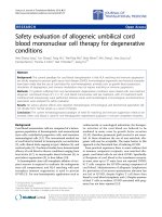
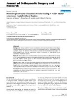
Thephysicalmodel(seeFigure1)comprisesfourtube
designs, e.g., straight pipe, conical spiral, in-plane spiral,
and helical spiral, f illed with two different nanofluids
(water-Al
2
O
3
and water-CuO). We assume that the low
particle volumetric concentration of nanoparticles (less
than 3%) in the base-fluid makes it behave like a single-
phase fluid and there is no agglomeration or sedimenta-
tion which occurs inside the tubes. A constant wall tem-
perature is prescribed along all sides of the channel wall;
the nanofluid is assumed incompressible and Newto-
nian. Furthermore, to ensure fidelity of the comparison
of heat transfer performance for each tube design, the
total length of each tube design is kept constant. Since
this study relates only to laminar flow, a precise numeri-
cal solution is adequate to simulate reality very closely.
Governing equations
In the tube, fluid flow and convective heat transfer are
taken into consideration. The con-servation equations of
mass, momentum, and energy are given by [24]
∇
·
(
ρ
nf
u
)
=0,
(1)
∇
· (ρ
nf
u ⊗ u)=−∇p + ∇·
μ
nf
∇u +(∇u)
T
,
(2)
∇
· (ρ
nf
c
p
,nf
uT)=∇·(k
nf
∇T)
.
(3)
In the abov e equations, r
nf
is the nanofluid fluid den-
sity, u is the fluid velocity, p is the pressure, μ
nf
is the
dynamic viscosity of the nanofluid, c
p,nf
is the specific
heat of the n anofluid and k
nf
is thermal conductivity of
the nanofluid.
Constitutive relations
Thermo-physical properties of nanofluids
The thermo-physical properties of nanofluid are func-
tions of particle volumetric concentrat ion and tempera-
ture. The nanofluid density is given by [24,29]
ρ
nf
= φρ
n
p
+(1− φ)ρ
w
,
where r
np
and r
w
is the nanoparticle density and
water density, respectively, while j is the particle volu-
metric concentration. The nanofluid viscosity is esti-
mated by [24]
μ
nf
= C
1
exp
(
C
2
φ
)
μ
w
,
(5)
Sasmito et al. Nanoscale Research Letters 2011, 6:376
/>Page 2 of 14
where
C
1
and
C
2
are constants (summarized in Table
1), and μ
w
is the viscosity of base-fluid.
The s pecific heat of nanofluid is assumed to b e a weighted
average of t he base-fluid and the nanoparticles, e.g.,
c
p,nf
=
φρ
np
c
p,np
+(1− φ)ρ
w
c
p,
w
ρ
nf
,
(6)
where c
p,np
and c
p,w
are the specific heats of nanopar-
ticle and water, respectively. In this model, the thermal
conductivity considers a combination of the static part
of Maxwell’stheoryandthedynamicparttakingthe
contribution of the Brownian motio n of nanoparticles,
defined as [24]
k
nf
=
k
np
+2k
w
− 2(k
w
− k
np
) φ
k
np
+2k
w
+(k
w
− k
np
) φ
k
w
+ k
1
βφρ
w
c
p,w
κT
ρ
np
d
np
f (T, φ)
,
(7)
where d
np
is the nanoparticle diameter,
k
1
is the Brow-
nian motion constant, k
np
and k
w
are thermal conductiv-
ity of nanoparticle and water, respectively. Here, the
effect of te mperature and particle volumetric concentra-
tion is taken into account in the Brownian motion from
empirical data given by [24]
β = β
1
(
100φ
)
β
2
,
(8)
f
(
T, φ
)
=
(
c
1
φ + c
2
)
T/T
0
+
(
c
3
φ + c
4
),
(9)
where b
1
, b
2
,
c
1
,
c
2
,
c
3
and
c
4
, are constants (see Table 1).
Thermo-physical properties of base-fluids
The base-fluid considered in this article is water.
Thermo-physical properties of water were obtained as
polynomial functions of temperature [43]; the water
density is defined by
ρ
w
= −3.570 × 10
−3
T
2
+1.88T + 753.2
,
(10)
while the water viscosity is given by
μ
w
=2.591× 10
−5
× 10
238.3
T − 143.2
,
(11)
and the thermal conductivity of water is calculated
from
k
w
= −8.354 × 10
−
6
T
2
+6.53× 10
−
3
T − 0.5981
.
(12)
The specific heat of water is considered constant at
c
p
,w
= 4200.
(13)
Properties of nanoparticles are given in Table 1.
Heat transfer performance
The heat transfer performance of the cooling channel is
discussed in terms of the figure of mer it, FoM, which is
defined as
FoM =
W
W
p
um
p
,
(14)
Figure 1 Schematic representation of (a) straight tube, (b) conical spiral tube, (c) in-plane spiral tube, and (d) helical spiral tube.
Sasmito et al. Nanoscale Research Letters 2011, 6:376
/>Page 3 of 14
where W
pump
is the pumping power required to drive
the fluid flow through the channel. It is given by
W
pump
=
1
η
p
um
p
˙
mp
.
(15)
Here, h
pump
is the pump efficiency (assumed to be
70%), W is the total heat transfer rate, and Δp is the
pressure drop in the cooling channel. The total heat
transfer rate is given as
W =
˙
mc
p
,nf
(T
m,in
− T
m,out
)
,
(16)
where
˙
m
is the mass flow rate and T
m,in
and T
m,out
are
mixed mean temperature at the inlet and outlet, respec-
tively. The mixed mean temperatures is calculated as
T
m
=
1
A
c
V
A
c
TudA
c
,
(17)
where A
c
is the cross section area of the channel and
V is the mean velocity given by
V =
1
A
c
A
c
udA
c
.
(18)
Boundary conditions
The boundary condit ions for the flow inside the channel
are prescribed as follows
• Inlet At the inlet, we prescri be inlet mass flow rate
and inlet temperature.
˙
m =
˙
m
in
, T = T
in
.
(19)
• Outlet Attheoutlet,wespecifythepressureand
streamwise gradient of the temperature is set to
zero; the outlet velocity is not known a priori but
needs to be iterated from the neighboring computa-
tional cells.
p = p
out,
n ·
(
k
nf
∇T
)
=0
.
(20)
• Walls At walls, we set no slip condition for v eloci-
ties and constant wall temperature.
u
= 0, T = T
wa
ll
.
(21)
In this article, a constant mass flow rate at a Reynolds
number (Re = rUD
h
/μ ) of approximately 1000 is pre-
scribed at the inlet for comparison purposes.
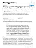
Numerics
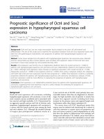
The computational domains (see Figure 2) were created
in AutoCAD 2010; the commercial pre-processor soft-
ware GAMBIT 2.3.16 w as used for meshing, labeling
boundary conditions and determines the computational
domain. Three different meshes, 1 × 10
5
,2×10
5
,and4
×10
5
, were tested and compared in terms of the local
pressure, velocities, and temperature to ensure a mesh
independent solution. It is found that mesh number of
around 2 × 10
5
gives about 1% deviation compared to
meshsizeof4×10
5
; whereas the results from mesh
number of 1 × 10
5
deviatebyupto8%comparedto
those from t he finest one. Therefore, a mesh of around
2×10
5
(20 × 20 × 500) elements was considered suffi-
cient for the numerical investigation purposes; a fine
structured mesh near the wall to resolve the boundary
layer and an incr easingly coarse r mes h in the middle of
the channel to reduce the computational cost.
Equations 1-3 together with appropriate boundary con-
ditions and constitutive relations comprising of five
Table 1 Base case and operating parameters
Parameter Value Unit
c
p,np,Al2O3
765 J · kg
-1
·K
c
p,np, CuO
540 J · kg
-1
·K
d
np, Al2O3
59 × 10
-9
m
d
np, CuO
29 × 10
-9
m
k
np, Al2O3
36 W · m
-1
·K
-1
k
np, CuO
18 W · m
-1
·K
-1
k
1
5×10
4
‾
1.381 × 10
-23
J·K
-1
r
np, Al2O3
3600 kg · m
-3
r
np, CuO
6510 kg · m
-3
˙
m
in
9×10
-3
kg · s
-1
p
out
101325 Pa
T
0
298.15 K
T
in
298.15 K
T
wall
323.15 K
c
1
2.8217 × 10
-2
‾
c
2
3.917 × 10
-3
‾
c
3
-3.0669 × 10
-2
‾
c
4
-3.91123 × 10
-3
‾
C
1
(Al
2
O
3
) 0.9830 ‾
C
2
(Al
2
O
3
) 12.959 ‾
C
1
(CuO) 0.9197 ‾
C
2
(CuO) 22.8539 ‾
b
1
(Al
2
O
3
) 8.4407 ‾
b
2
(Al
2
O
3
) -1.07304 ‾
b
1
(CuO) 9.881 ‾
Β
2
(CuO) -0.9446 ‾
Sasmito et al. Nanoscale Research Letters 2011, 6:376
/>Page 4 of 14
dependent variables, u, v, w, p,andT,weresolvedusing
the finite volume solver Fluent 6.3.26. User-Defined func-
tions (UDF) were written in C language to account for
particle volumetric concentration and temperature-depen-
dence of the thermo-physical properties of the nanofluids.
The equations were solved wit h the well-known Se mi-
Implicit Pressure-Linked Equation (SIMPLE) algorithm,
first-order upwind discretization and Algebraic Multi-grid
(AMG) method. As an indication of the computational
cost, it is noted that on average, around 200-500 iterations
and 500 MB of Random Access Memory (RAM) are
needed for convergence criteria for all relative residuals of
10
-6
, this takes 5-30 min on a workstation with a quad-
core processor (1.83 GHz) and 8 GB of RAM.
Results and discussion
The numerical simulations were carried out for four dif-
ferent tube geometri es, four differe nt nanofluid concen-
trations, and two different nanofluid suspensions. The
base-case conditions together with the physical para-
meters are listed in Table 1, while the geometric details
can be found in Table 2.
Validation
When developing and implementing mathematical model to
predict the behavior of nanofluid heat transfer, one needs t o
pay special attention to validation of the model due to
inherent complexity of coupled physical phenomena and
interaction between base-fluid and nanoparticle. In this study,
we ai m to validate our model with an experimental nanofluid
heat transfer by Anoop e t al. [19], which has error of ap proxi-
mately 4%. The heat transfer perform ance of nanofluid flows
in circular tube with diameter 4.75 × 10
-3
m and length of 1.2
m i s a pproximated with 2D axisymmetric model, see Anoop
et al. [19] for d etails of the experimental setup.
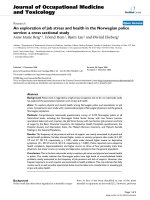
The validation is initiated with heat transfer perfor-
mance of water flowing at a constant Reynolds approxi-
mately 1580; after which, the heat transfer performance of
4 wt% of water-Al
2
O
3
nanofluid with nanoparticle size 45
nm flows at Reynolds approximately 1588 is compared, as
depicted in Figure 3. It is found that the model predictions
agree well with the heat transfer performance from
Figure 2 Computational domain for (a) straight tube, (b) conical spiral tube, (c) in-plane spiral tube, and (d) helical spiral tube.
Table 2 Geometric parameters
Parameter Value Unit
w 1.00 × 10
-2
m
s 1.00 × 10
-2
m
R
pi
2.00 × 10
-2
m
R
po
9.00 × 10
-2
m
R
ci
2.00 × 10
-2
m
R
co
9.00 × 10
-2
m
R
h
4.00 × 10
-2
m
L 1.20 m
Sasmito et al. Nanoscale Research Letters 2011, 6:376
/>Page 5 of 14
experimental counterpart for both water and nanofluid.
This implies that the model correctly accounts for the fun-
damental physics associated with nanofluid heat transfer.
Effect of geometry
Base-fluid
One of the key factors that determine the heat transfer per-
formance is the cross-sectional tube geometry. This study
examines four different square cross section tubes geome-
tries: straight, conical spiral, in-plane spiral, and helical
spiral with water as the base working fluid. Since the con-
vective heat transfer inside the tube is directly linked to
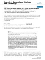
flow behavior, it is of interest to investi gate the flow pat-
terns inside the tubes. In our previous studies [1-3], albeit
using air as working fluid, showed that the presence of cen-
trifugal force due to curvature leads to significant radial
pressure gradients in flow core region. In the proximity the
inner and outer walls of the coils, however, the axial velo-
city and the centrifugal force wil l approach zer o. Hence, to
balance the momentum transport, secondary flow should
develop along the outer wall. This is indeed the case, as
can be seen in Figure 4, where the secondary flow with
higher velocities is generated in the outer wall region of
coiled tubes (see Figure 4b,c,d). However, this is not the
case for the straight tube (Figure 4a) as a fully developed
flow exists inside the tube. It is noted that at this particular
Reynolds number (approximately 1000), the secondary
flows a ppear as one-pair for conical spiral and helical spi ral
tubes; whereas in the in-plane spiral tube, the secondary
flows appeared as two-pairs.
The presence of secondary flow with high velocities is
expected to have direct impact on the heat transfer rate.
This can be inferred from Figure 5 which presents tem-
perature distribution over the cross sections of various
tube designs. As can be seen from Figure 5, temperatures
in coiled tubes are higher than in straight tube at the
same axial distance which indicates that coiled tubes
have higher heat transfer rate when compared to that of
the straight tube due to the presence of secondary flows.
It is also worth noting that the higher intensity of sec-
ondary flow will tend to lead to higher heat transfer rate.
Now looking at the mixed mean temperature and total
heat transfer variation along the tube length (see dotted
line in Figure 6), it is noted that coiled tubes have superior
heat transfer performa nce when compared to that of the
straight tube; the total heat transfer rate can be up to
0 50 100 150 200 250
0
500
1000
1500
2000
2500
3000
x/D
h, W m
−2
K
−1
water (exp)
nanofluid (exp)
water (sim)
nanofluid (sim)
Figure 3 Comparison of heat transfer coefficient between simulation (lines) a nd experimental data [19] (symbols) for water and
nanofluid.
Sasmito et al. Nanoscale Research Letters 2011, 6:376
/>Page 6 of 14
almost three times higher than that for the straight tube.
In the near-inlet region, the heat transfer performance of
in-plane spiral yields the best result among others, fol-
lowed by conical spiral and helical spiral; whereas, in the
near-outlet region, the helical coil performs the best fol-
lowed by in-plane spiral and conical spiral. This indicates
that, for water as working fluid, in-plane spiral is more
effective to be used in short tube applications, while the
helical spiral is more effective for long tube applications in
terms of amount of heat transferred.
Nanofluids
Four square cross section tube geometries were examined
for flow of nanofluid suspensions of water-Al
2
O
3
with
nanoparticle concentration of 1%. The results are depicted
in Figure 6 where the mixed mean temperatur e and total
heat transfer of base-fluid and nanofluids are shown. It is
noted that adding 1% concentration o f Al
2
O
3
in water
improves the heat transfer performance. The total heat
transfer for straight tube increases up to 50% as compared
to that for water, whereas for coiled t ubes, the heat transfer
improves by about 50% in the near-inlet region and then
decreases toward the outlet. Furthermore, among the coiled
tube geometries, in-plane spiral gives the highest heat
transfer improvement, followed by helical spiral and conical
spiral tubes. This implies t hat in-plane s piral tube may have
potential application to be used along with nanofluid due
to its higher heat transfer performance. Therefore, the most
of the fol lowing results r efer to in-plane spiral coils.
Effect of nanoparticle concentration
The amount of nanoparticles suspended in the base-
fluid plays a significant role in deter-mining heat
Figure 4 Velocity profiles of water flow in (a) straight duct; (b) conical spiral duct; (c) in-plane spiral duct; and (d) helical spiral duct at
L =50cm.
Sasmito et al. Nanoscale Research Letters 2011, 6:376
/>Page 7 of 14
transfer performance. Intuitively, adding larger amount
of nanoparticles in the base-fluid increases thermal
conductivity of the nanofluid; however, care has to be
taken as it also increases the friction factor and may
reduce the stability of nanofluids due to agglomeration
and sedimentation. To study the impact of these fac-
tors, we investigated four different nanoparticle con-
centrations: 0, 1, 2, and 3% of Al
2
O
3
in the base-fluid
(water). Figure 7 displays the velocity profiles for the
in-plane spiral tube for various nanoparticle concentra-
tions. Interestingly, the velocity profiles are not
strongly affected by the additional nanoparticle suspen-
sion, especially at low concentrations. We note that at
1and2%ofAl
2
O
3
concentration, there is no signifi-
cant difference on the secondary flow development
inside the tube; whereas, at 3% Al
2
O
3
concentration,
the effect of nanofluid suspension becomes stronger:
the secondary flow appears in two-pairs as compared
to that in one-pair at lower nanoparticle concentra-
tions. A plausible explanation is the fact that nanofluid
suspension does not significantly change viscosity of
the fluid. Conversely, this is not the case for thermal
conductivity of the nanofluid, as mirrored in Figure 8,
where the addition of small amount of nanoparticle
(1%) drastically changes the temperature profiles inside
the tube. Furthermore, the temperature profiles for
higher amount of nanoparticle concentration (2 and
3%) also slightly change, but they are mainly affected
by the hydrodynamics (secondary flows).
Proceeding to the local mixed mean temperature and
total heat transfer along the tube, as illustrated in
Figure 9, it is clearly seen that additional small amounts
Figure 5 Temperature distribution of water flow in (a) straight duct; (b) conical spiral duct; (c) in-plane spiral duct; and (d) helical
spiral duct at L =50cm.
Sasmito et al. Nanoscale Research Letters 2011, 6:376
/>Page 8 of 14
Figure 6 (a) Mixed mean temperature an d (b) total heat tran sfer at various coiled t ubes along the tube lengt h for wa ter [ ] and
water with 1% Al
2
O
3
[-].
Figure 7 Velocity profiles of (a) water, (b) water with 1% Al
2
O
3
, (c) water with 2% Al
2
O
3
, and (d) water with 3% Al
2
O
3
flows inside an
in-plane coiled tube at L =50cm.
Sasmito et al. Nanoscale Research Letters 2011, 6:376
/>Page 9 of 14
Figure 8 Temperature distribution of (a) water, (b) water with 1% Al
2
O
3
, (c) water with 2% Al
2
O
3
, and (d) water with 3% Al
2
O
3
flows
inside an in-plane coiled tube at L =50cm.
Figure 9 (a) Mixed mean temperature and (b) total heat transfer at various concentrations of Al
2
O
3
inside an in-plane coiled tube
along the tube length.
Sasmito et al. Nanoscale Research Letters 2011, 6:376
/>Page 10 of 14
of nanoparticles improves the heat transfer performance
significantly, especially in the near-in let area. How-ever,
increase in nanoparticle concentration leads to a reduc-
tion of total heat transfer along the tube by approxi-
mately 5%. It is noteworthy that adding large amounts
of nanoparticles in the suspension is not effective in
enhancing heat transfer. Moreover, low nanoparticle
concentration also has advantages of better stability of
the suspension as it minimizes agglomeration and
sedimentation.
Effect of nanofluid type
So far, the simulated nanofluid type chosen was water-
Al
2
O
3
; it is, therefore, of interest to see the heat transfer
performance for a different nanofluid. In this study, we
compare the performance of water-Al
2
O
3
and water-
CuO nanofluids. Note that other types of nanofluid
suspensions can be easily simulated within the frame-
work of this model once their properties are known.
Figure 10 shows temperature profiles for a n in-plane
spiral tub e flowing through with water (Figure 10a), 1%
of Al
2
O
3
nanofluid (Figure 10b) and 1% of CuO nano-
fluid (Figure 10c). We note that the temperature profiles
for both nanofluids (Figure 10b,c) are much higher than
that of water (Figure 10a). Closer inspection reveals that
a slig htly larger area of higher temperature exists for the
Al
2
O
3
suspension (Figure 10b) as compared to that for
CuO suspension (Figure 10c). This is attributed to the
stronger secondary flow observed in Al
2
O
3
nanofluid
when compared to that of the CuO nanofluid (not
shown here due to page limitation).
The heat transfer performance of two different nano-
fluid types is further evaluated in terms of the local
mixed mean temperature and total heat transfer. As
seen in Figure 11, the mixed mean temperature for the
nanofluid is around 15% higher than that of water.
There is no discernible difference between Al
2
O
3
and
CuO suspensions in terms of the mixed mean tempera-
ture. For total heat transfer, Al
2
O
3
gives somewhat
higher heat transfer (approximately 5%) when compared
to the CuO nanofluid. Therefore, it can be deduced that
Al
2
O
3
nanofluid performs better heat transfer perfor-
mance than that of CuO nanofluid, but not significantly.
The stability and cost would decide the selection
between these two nanofluids.
Overall heat transfer performance
A summary of heat transfer performance for all cases
considered in this article is presented in Figure 12. Here
several features are apparent; foremost among them is
that the coiled tubes provide significantly higher heat
transfer than that of straight tube, and addition of a
small amount of nanoparticles in the base-fluid
enhances heat transfer further (see Figure 12a). It is
313
313
314
316
317
318
320
(a)
water
inner wall
outer wall
320
321
322
(b)
outer wall
water-Al2O3 1%
inner wall
320
321
322
inner wall
outer wall
water-CuO1%
(c)
313 314 315 316 317 318 319 320 321 322 323
Figure 10 Temperature distribution of (a) water, (b) water with
1% Al
2
O
3
, and (c) water with 1% CuO flows inside an in-plane
coiled tube at L =50cm.
Sasmito et al. Nanoscale Research Letters 2011, 6:376
/>Page 11 of 14
Figure 11 (a) Mixed mean temperature and (b) total heat transfer of water and nanofliuds (Al
2
O
3
and CuO) inside an in-plane coiled
tube along the tube length.
Figure 12 (a) Total heat transfer, (b) pressure drop, and (c) Figure of Merit (FoM) of water and nanofluids in various tubes.
Sasmito et al. Nanoscale Research Letters 2011, 6:376
/>Page 12 of 14
noted that t he maximum heat transfer performance is
achieved at 1% nanoparticle concentration, decreasing
with higher amounts of nanoparticles.
Aside from higher heat transfer performance, keeping
pressure drop at a minimum is of interest for reducing
the operating cost and saving energy. Figure 12b shows
a summary of the pressure drop required for all cases
studied. Note that the mass flow rate is kept constant in
all cases; hence, it can be used directly to represent the
pumping power required. The straight channel requires
the lowest pressure drop among all cases; whereas the
coiled tube designs require more than d ouble the pres-
sure drop of the straight channel. Among t he coiled
tubes, helical spiral tube needs the highest pressure
drop, followed by in-plane spiral and conical spiral
tubes. An interesting phenomenon is observed at a
nanofluid concentration of 1% when the pressure drop
for coiled tubes is slightly lower than that for water.
This is due to the fact that at low particle concentra-
tions, the particle volumetric concentration affects the
nanofluid viscosity negligibly while the effect of tem-
perature increases in the nanofluid thermo-physical
properties.
With respect to the heat transfer performance and
pressure drop required in the system, the “Figure of
Merit” concept is introduced as a measure of the heat
transferred per unit pumping power (see Equation 14
for details). Figure 12c presents the computed figures of
merit for various tube geometries, nanofluid concentra-
tions and nanofluid types. It is found that apart from
the higher heat transfer rate, the coiled tubes have lower
figures of merit than those of the straight tube. This can
be explained by the higher pressure drops required in
the coiled systems (see Figure 12b ). Among all coiled
tubes tested, the conical spiral tube gives the highest fig-
ureofmerit,followedbyin-planespiralandconical
spiral tubes. Furthermore, for the straight tube, the addi-
tion of nanoparticles improves the figure of merit signif-
icantly, albeit it decreases with increasing concentration.
For coiled tubes filled with nanofluids, on the other
hand, the improvement of figure of merit is only shown
at low particle concentration of 1% and then it drops
lower than that of water when more nanoparticles are
added. Clearly, these results suggest that one can add
nanoparticle up to 1% volumetric concentration to
water to enhance heat transfer performance in coiled
tubes; higher nanoparticle concentrations are not
recommended.
Concluding remarks
A computational study was conducted to investigate the
laminar flow heat transfer performance of square cross
section tubes, i.e., straight, conical spiral, in-plane spiral,
and helical spiral, with water and two nanofluids. It is
found that adding 1% nanoparticle volumetric concen-
tration improves heat transfer performance and the fig-
ure of merit for all tubes. However, higher amounts of
nanoparticles is not recommended. In-plane spiral tubes
give better performance than other coiled tubes for
nanofluids. Furthermore, Al
2
O
3
nanofluid gives slightly
bett er heat transfer performance than CuO nanofluid in
coiled tubes. Future study will evaluate various modeling
approaches for nanofluid heat transfer, e.g., single-phase,
two-phase mixture, Euler-Euler, and Euler-Lagrange
models, in coils with resp ect to the effect of secondary
flow to the nanoparticle concentration.
Abbreviations
AMG: algebraic multi-grid; CFD: computational fluid dynamics; RAM: random
access memory; SIMPLE: semi-implicit pressure-linked equation; UDF: user-
defined functions. List of symbols: A
c
: Cross section area (m
-2
); c
p
: Specific
heat (J · kg
-1
·K
-1
);
C
: Viscosity parameter; d
p
: Particle diameter (m); D
h
:
Hydraulic diameter (= 4A
c
/P
c
) (m); FoM: Figure of merit; h: Heat transfer
coefficient (W · m
-2
·K
-1
); k: Thermal conductivity (W · m
-1
·K
-1
); κ: Boltzmann
constant (J · K
-1
);
k
: Brownian motion constant; L: Total length channel (m);
˙
m
: Mass flow rate (kg · s
-1
); p: Pressure (Pa); P
c
: Cross section perimeter (m);
R: Radius of coil (m); Re: Reynolds number (= ρUD
h
/μ); s: Spacing (m); T:
Temperature (K); u, u, v, w, U: Velocity (m · s
-1
); V: Mean velocity (m · s
-1
); w:
Channel width; W: Total heat transfer (J · s
-1
); W
pump
: Pumping power (W).
Greek: β: Brownian motion parameter; ρ: Fluid density (kg · m
-3
); j: Particle
volumetric concentration (%); η: Efficiency (%); μ: Dynamic viscosity (Pa · s).
Subscripts: c: Conical spiral; h: Helical spiral; i: Inner; in: Inlet; L: Length;
mean: Mean value; norm: Normalized value; nf: Nanofluids; np: Nanoparticle;
o: Outer; out: Outlet; p: In-plane spiral; pump: Pump; w: Water; wall: Wall.
Author details
1
Department of Mechanical Engineering, National University of Singapore, 9
Engineering Drive 1, Singapore, 117576 Singapore
2
Minerals, Metals and
Materials Technology Centre, National University of Singapore, 9 Engineering
Drive 1, Singapore 117576 Singapore
Authors’ contributions
APS developed the mathematical model together with JCK, built
computational code, carried out the numerical simulation and writing the
manuscript. JCK prepared created the computational domain, conducted
post-processing and participated in preparing manuscript. Both APS and JCK
performed the analysis. ASM supervised the whole work and edited the
manuscript. All authors read and approved the final manuscript.
Competing interests
The authors declare that they have no competing interests.
Received: 30 October 2010 Accepted: 9 May 2011
Published: 9 May 2011
References
1. Kurnia JC, Sasmito AP, Mujumdar AS: Evaluation of heat transfer
performance of helical coils of non-circular tubes. J Zhejiang Univ Sci A
2011, 12:63-70.
2. Kurnia JC, Sasmito AP, Mujumdar AS: Numerical investigation of laminar
heat transfer performance of various cooling channel designs. Appl
Therm Eng 2011, 31:1293-1304.
3. Kurnia JC, Sasmito AP, Mujumdar AS: Laminar convective heat transfer for
in-plane spiral coils of non-circular cross sections ducts: a computational
fluid dynamics study. Therm Sci 2011.
4. Naphon P: Thermal performance and pressure drop of the helical-coil
heat exchangers with and without helically crimped fins. Int Commun
Heat Mass Transf 2007, 34:321-330.
5. Auteri F, Belan M, Ceccon S, Gibertini G, Quadrio M: Endoscopic PIV in a
helical pipe coil. XIV AIVELA Conference, Rome, 6-7 September 2006 .
Sasmito et al. Nanoscale Research Letters 2011, 6:376
/>Page 13 of 14
6. Mandal MM, Kumar V, Nigam KDP: Augmentattion of heat transfer
performance in coiled flow inverter vis-a-vis conventional heat
exchanger. Chem Eng Sci 2010, 65:999-1007.
7. Liou TM: Flow visualization and LDV measurement of fully developed
laminar flow in helically coiled tubes. Exp Fluids 1992, 12:332-338.
8. Mandal MM, Nigam KDP: Experimental study of pressure drop and heat
transfer of turbulent flow in tube helical heat exchanger. Ind Eng Chem
Res 2009, 48:9318-9324.
9. Agrawal S, Nigam KDP: Modeling of coiled tubular chemical reactor.
Chem Eng J 2001, 84:437-444.
10. Norouzi M, Kahyani MH, Nobari MRH, Demneh MK: Convective heat
transfer of viscoelastic flow in curved duct. World Acad Sci Eng Technol
2009, 56:327-333.
11. Kaya O, Teke I: Turbulent forced convection in helically coiled square
duct with one uniform temperature and three adiabatic walls. Heat Mass
Transf 2005, 42:129-137.
12. Kumar V, Faizee B, Mridha M, Nigam KDP: Numerical studies of a tube-in-
tube helically coiled heat exchanger. Chem Eng Process 2008,
47:2287-2295.
13. Kumar V, Gupta P, Nigam KDP: Fluid flow and heat transfer in curved
tubes with temperature dependent properties. Ind Eng Chem Res 2007,
46:3226-3236.
14. Vashisth S, Kumar V, Nigam KDP: A review on the potential application of
curved geometries in process industry. Ind Eng Chem Res 2008,
47:3291-3337.
15. Naphon P, Wongwises S: A review of flow and heat transfer
characteristics in curved tubes. Renew Sust Energy Rev 2006, 10:463-490.
16. Choi SUS: Enhancing Thermal Conductivity of Fluids with Nanoparticles,
Developments and Applications of Non-Newtonian Flows New York: ASME;
1995, 99-105.
17. Wang X-Q, Mujumdar AS: Heat transfer characteristics of nanofluids: a
review. Int J Therm Sci 2007, 46:1-19.
18. Choi SUS, Zhang ZG, Yu W, Lockwood FE, Grulke EA: Anomalously thermal
conductivity enhancement in nanotube suspensions. Appl Phys Lett 2001,
79:2252-2254.
19. Anoop KB, Sundararajan T, Das SK: Effect of particle size on the
convective heat transfer in nanofluid in the developing region. Int J Heat
Mass Transf 2009, 52:2189-2195.
20. Hamed Mosavian MT, Heris SZ, Etemad SG, Esfahany MN: Heat transfer
enhance-ment by application of nano-powder.
J Nanopart Res 2010,
12:2611-2619.
21. Liao L, Liu Z, Bao R: Forced convective flow drag and heat transfer
characteristics of CuO nanoparticle suspensions and nanofluids in a
small tube. J Enhanced Heat Transf 2010, 17:45-57.
22. Lai WY, Vinod S, Phelan PE, Phraser R: Convective heat transfer for water-
based alumina nanofluids in a single 1.02-mm tube. J Heat Transf 2009,
131:1-9.
23. Rea U, McKrell T, Hu L, Buongiorno J: Laminar convective heat transfer
and viscous pressure loss of alumina-water and zirconia-water
nanofluids. Int J Heat Mass Transf 2009, 52:2042-2048.
24. Vajjha RS, Das DK, Namburu PK: Numerical study of fluid dynamic and
heat transfer performance of Al
2
O
3
and CuO nanofluids in the flat tubes
of a radiator. Int J Heat Fluid Flow 2010, 31:613-621.
25. Mokmeli A, Saffar-Avval M: Prediction of nanofluid convective heat
transfer using dispersion model. Int J Therm Sci 2010, 49:471-478.
26. Haghshenas MF, Esfahany MN, Talaie MR: Numerical study of convective
heat transfer of nanofluids in a circular tube two-phase model versus
single-phase model. Int Commun Heat Mass Transf 2010, 37:91-97.
27. Bianco V, Chiacchio F, Manca O, Nardini S: Numerical investigation of
nanofluids forced convection in circular tubes. Appl Therm Eng 2009,
29:3632-3642.
28. Akbarnia A, Laur R: Investigating the diameter of solid particles effect on
a laminar nanofluid flow in a curved tube using two phase approach. Int
J Heat Fluid Flow 2009, 30:706-714.
29. Das SK, Choi SU, Yu W, Pradeep T: Nanofluids: Science and Technology
Hoboken: Wiley; 2007.
30. Wang XQ, Mujumdar AS: A review on nanofluids-Part I: theoretical and
nu-merical investigations. Braz J Chem Eng 2008, 25:613-630.
31. Wang X-Q, Mujumdar AS: A review on nanofluids-Part II: experiments and
applications. Braz J Chem Eng 2008, 25:631-648.
32. Chandrasekar M, Suresh S: A review on the mechanisms of heat transport
in nanofluids. Heat Transf Eng 2009, 30:1136-1150.
33. Daungthongsuk W, Wongwises S: A critical review of convective heat
transfer nanofluids. Renew Sust Energy Rev 2007, 11:797-817.
34. Trisaksri V, Wongwises S: Critical review of heat transfer characteristics of
nanofluids. Renew Sustain Energy Rev 2007, 11:512-523.
35. Kakác S, Pramuanjaroenkij A: Review of convective heat transfer
enhancement with nanofluids. Int J Heat Mass Transf 2009, 52:3187-3196.
36. Wang L-Q, Fan J: Nanofluids research: Key issues. Nanoscale Res Lett 2010,
5:1241-1252.
37. Godson L, Raja B, Lai DM, Wongwises S: Enhancement of heat transfer
using nanofluids: a review. Renew Sustain Energy Rev 2010, 14:629-641.
38. Murshed SMS, Leong KC, Yang C: Thermophysical and electrokinetic
properties of nanofluids-a critical review. Appl Therm Eng 2008,
28:2109-2125.
39. Das SK, Choi SUS, Patel HE: Heat transfer in nanofluids-a review. Heat
Transf Eng 2006, 27:3-19.
40. Wen D, Lin G, Vafaei S, Zhang K: Review of nanofluids for heat transfer
applications. Particuology 2009, 7:141-150.
41. Li Y, Zhou J, Tung S, Schneider E, Xi S: A review on development of
nanofluid preparation and characterization. Powder Technol 2009,
196:89-101.
42. Yu W, France DM, Routbort JL, Choi SUS: Review and comparison of
nanofluid thermal conductivity and heat transfer enhancements. Heat
Transf Eng 2008, 29:432-460.
43. Kays W, Crawford M, Weigand B: Convective Heat and Mass Transport. 4
edition. Singapore: MacGraw Hill; 2005.
doi:10.1186/1556-276X-6-376
Cite this article as: Sasmito et al.: Numerical evaluation of laminar heat
transfer enhancement in nanofluid flow in coiled square tubes.
Nanoscale Research Letters 2011 6:376.
Submit your manuscript to a
journal and benefi t from:
7 Convenient online submission
7 Rigorous peer review
7 Immediate publication on acceptance
7 Open access: articles freely available online
7 High visibility within the fi eld
7 Retaining the copyright to your article
Submit your next manuscript at 7 springeropen.com
Sasmito et al. Nanoscale Research Letters 2011, 6:376
/>Page 14 of 14