Báo cáo hóa học: " A review of experimental investigations on thermal phenomena in nanofluids" ppt
Bạn đang xem bản rút gọn của tài liệu. Xem và tải ngay bản đầy đủ của tài liệu tại đây (982.22 KB, 21 trang )
NANO REVIEW Open Access
A review of experimental investigations on
thermal phenomena in nanofluids
Shijo Thomas and Choondal Balakri shna Panicker Sobhan
*
Abstract
Nanoparticle suspensions (nanofluids) have been recommended as a promising option for various engineering
applications, due to the observed enhancement of thermophysical properties and improvement in the
effectiveness of thermal phenomena. A number of investigations have been reported in the recent past, in order
to quantify the thermo-fluidic behavior of nanofluids. This review is focused on examining and comparing the
measurements of convective heat transfer and phase change in nanofluids, with an emphasis on the experimental
techniques employed to measure the effective thermal conductivity, as well as to characterize the thermal
performance of systems involving nanofluids.
Introduction
The modern trends in process intensification and device
miniaturization have resulted in the quest for effective
heat dissipation methods from microelectronic systems
and packages, owing to the increased fluxes and the
stringent limits in operating temperatures. Conventional
methods of heat removal have been found rather inade-
quate to deal with such high intensities of heat fluxes. A
number of studies have been reported in the recent
past, on the heat transfer characteristics of suspensions
of particulate solids in liquids, which are expected to be
cooling fluids of enhanced capabilities, due to the much
higher thermal conductivities of the suspended solid
particles, compared to the base liquids. However, most
of the earlier studies were focused on suspensions of
millimeter or micron sized particles, which, although
showed some enhancement in the cooling behavior, also
exhibited problems such as sedimentation and clogging.
The gravity of these problems has been more significant
in systems using mini or micro-channels.
A much more recent introduction into the domain of
enhanced-property cooling fluids has been that of nano-
particle suspensions or nanofluids. Advances in nano-
technology have made it possible to synthesize parti cles
in the size range of a few nanometers. These particles
when suspended in common heat transfer fluids, pro-
duce the new category of fluids termed nanofluids. The
observed advantages of nanofluids over heat transfer
fluids with micron sized particles include better stability
and lower penalty on pressure drop, along with reduced
pipe wall abrasion, on top of higher effective thermal
conductivity.
It has been observed by various investigators that the
suspension of nanoparticles in base f luids show anoma-
lous enhancements in various thermophysical properties,
which become increasingly helpful in making their use
as cooling fluids more effective [1-4]. While the reasons
for the anomalous enhancements in the effective proper-
ties of the suspensions have been under investigation
using fundamental theoretical models such as molecular
dynamics simulations [5,6], the practical application o f
nanoflui ds for developing cooling solutions, especially in
miniat ure domains have already been undertaken exten-
sively and effectively [7,8]. Quantitative analysis of the
heat transfer capabilities of nanofluids based on experi-
mental methods has been a topic of current interest.
The present article attempts to review the various
experimental techniques used to quantify the thermal
conductivity, as well as to investigate and characterize
thermal phenomena in nanofluids. Different measure-
ment techniques for thermal conductivity are reviewed,
and extensive discussions are presented o n the charac-
terization of thermal phenomena such as forced and
free convection heat transfer, circulation in liquid loops,
boiling and two phase flow in nanofluids, in the sections
to follow.
* Correspondence:
School of Nano Science and Technology, NIT Calicut, Kerala, India
Thomas and Balakrishna Panicker Sobhan Nanoscale Research Letters 2011, 6:377
/>© 2011 Thomas and Balakrishna Panicker Sobhan; licensee Springer. This is an Open Access article distributed under the terms of the
Creative Commons Attribution License ( es/by/2.0), which permits unrestricted use, distribution, and
reproductio n in any me dium, provided the original work is properly cited.
Thermal conductivity
The techniques employed for measurement of thermal
conductivity can be broadly classified into transient and
steady state methods. The transient measurement tech-
niques frequently used are the hot wire method, the hot
strip method, the temperature oscillation method and
the 3ω method. Steady-state measurement using a ‘cut-
bar apparatus’ has also bee n reported. These methods
are reviewed below.
The short hot wire (SHW) me thod
The transient short hot wire (SHW) method used to
measure the thermal conductivity and thermal diffusivity
of nanofluids has been described by Xie et al. [9,10].
The technique is based on the comparison of experi-
mental data with a numerical solution of the two-
dimensional transient heat conduction applied to a
short wire with the same length-to-diameter ratio and
boundary conditions as in the experimental setup.
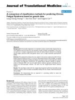
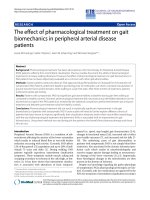
The experimental apparatus consists of a SHW probe
and a teflon cell of 30 cm
3
volume. The dimensions of
the SHW probe are shown in Figure 1. The SHW probe
is mounted on the teflon cap of the cell. A short plati-
num wire of length 14.5 mm and 20 μmdiameteris
welded at both e nds to platinum lead wires of 1.5 mm
in diameter. The platinum probe is coated with a thin
layer (1 μm) of alumina for insulation, thus preventing
electrical leakage. Before and after the application of the
Al
2
O
3
film coating, the effective length and radius of the
hotwireandthethicknessoftheAl
2
O
3
insulation film
are calibrated. Figure 1b shows the dimensions of the
Teflon cell used for measurements in nanofluids. Two
thermocouples located at the same height, at the upper
and lower welding spots of the hot wire and lead wires,
respectively, monitor the temperature homogeneity. The
temperature fluctuations are minimized by placing the
hot wire cell in a thermostatic bath at the measurement
temperature.
In the calculation method, the dimensionless volume-
averaged temperature rise of the hot wire, θ
v
[= (T
v
-
T
i
)/(q
v
r
2
/l)] is approximated by a linear equation in
terms of the logarithm of the Fourier number Fo [=at/
r
2
], where T
i
and T
v
are the initial liquid temperature
and volume averaged hot-wire temperature, q
v
the heat
rate generated per unit volume, r the radius of the
SHW, t is the time, and l and a the thermal conductiv-
ity and the t hermal diffusivity of liquid, respectively.
The coefficie nts of the linear equation, A and B,are
determined by the least squares method fo r a range of
Fourier numbers corresponding to the measuring per-
iod. The measured temperature rise of the wire ΔT
v
[=T
v
- T
i
] is also approximated by a linear equation
with coefficients a and b, det ermined by the least
square method for the time range before o nset of nat-
ural convection. Thermal conductivity (l) and thermal
diffusivity (a) of nanofluids are obtained as l =(VI/πl)
(A/a)anda = r
2
exp[(b/a)-(B/A)], where l is the
length of the hotwire, and V and I are the voltage and
current supplied to the w ire. The uncertainties of the
thermal conductivity and thermal diffusivity measure-
ments using SHW have been estimated to be within 1.0
and 5.0%, respectively.
Figure 1 Short hot wire probe apparatus of Xie et al. [9].
Thomas and Balakrishna Panicker Sobhan Nanoscale Research Letters 2011, 6:377
/>Page 2 of 21
Temperature oscillation technique
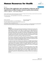
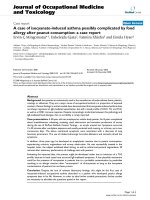
Das et al. [11] proposed and demonstrated the tempera-
ture oscillation method for estimating thermal conduc-
tivity and thermal diffusivity of nanofluids . The met hod
can be understood with thehelpofFigure2,which
shows a cylindrical fluid volume analyzed, with periodic
temperature oscillations applied at surfaces A and B.
The temperature oscillati ons are generated using Peltier
elements attached to reference layer. The Peltier ele-
ments are powered by a DC power source. The real
measurable phase shift and amplitude ratio of tempera-
ture oscillation can be expressed as,
G = arctan
Im(B
∗
)
Re
(
B
∗
)
(1)
and
u
L
u
L
/
2
=
Re (B
∗
)
2
+ Im (B
∗
)
2
,
(2)
where G is the phase shift, u ampl itude in Kelvin, and
L thickness of fluid sample in meter.
The complex amplitude ratio between the mid-point
of the specimen and the surface can be given by
B
∗
=
2u
L
e
iG
L
u
L
e
iG
L
+ u
o
e
iG
o
cosh
L
2
iω
α
1
/
2
,
(3)
where a is the thermal diffusivity and the angular
velocity, ω, is given by
ω =
2π
t
p
.
(4)
The phase and amplitude of temperature oscillation at
thetwosurfacesaswellasatthecentralpointC,gives
the thermal diffusivity of the fluid, from Equations 1 or
2.
The temperature os cillationinthereferencelayerat
the two boundaries of the t est fluid yields the thermal
conductivity. The frequency of temperature oscillation
in the refer ence layer, in the Peltier element and that in
the test fluid are the same.
The complex amplitude ratio at x =-D (D being the
thickness of the reference layer) and x = 0 is given by
B
∗
R
=cosh
ζ
D
√
i
− C sinh
ζ
D
√
i
×
(u
L
/u
o
)e
i(G
L
−G
0
)
− cosh
ξ
L
√
i
sin
ξ
L
√
i
(5)
where
ξ = x
ω
α
and
ζ
= x
ω
α
R
.ThesubscriptR
represents the reference layer.
C =
λ
λ
R
α
α
R
(6)
where l is the thermal conductivity of the fluid.
The real phase shift and amplitude attenuation of the
reference layer is given by
G
R
= arctan
Im(B
∗
R
)
Re(B
∗
R
)
,
(7)
Figure 2 The fluid volume for analysis corresponding to the experimental setup of Das et al. [11].
Thomas and Balakrishna Panicker Sobhan Nanoscale Research Letters 2011, 6:377
/>Page 3 of 21
u
D
u
o
=
Re (B
∗
R
)
2
+ Im (B
∗
R
)
2
.
(8)
The thermal diffusivity of the reference layer being
known either from Equations 7 or 8, the thermal conduc-
tivity of the specimen can be evaluated from Equation 6.
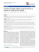
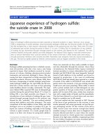
The test cell is a flat cylindrical cell as shown in Figure 3,
which is cooled on both of the ends using a thermostatic
bath. DC power is applied to the Peltier element. A num-
ber of thermocouples measure the temperatures in the
test section which are amplified, filtered, and fed to the
data ac quisitio n system. The frame of the cell is made of
POM (polyoxymethylene), which acts as the first layer of
insulation. The frame has a 40-mm diameter ca vity to
hold the test fluid. Two disk type reference materials of 40
mm diameter and 15 mm thickness are ke pt on top and
bottom side of the cavity. The space for the test fluid has a
dimension of 40 mm diameter and 8 mm thickness. The
fluid is filled through a small hole in the body of the cell.
Temperatures are measured at the interface of the Peltier
element and the reference layer, at the interfa ce of the
reference layer and test fluid and the central axial plane of
the test fluid. The thermocoupl es are held precisely cen-
tralized. The entire cell is externally insulated. The experi-
mental setup was calibrated by measuring the thermal
diffusivity of demineralized and distilled water over the
temperature range of 20 to 50°C. The results showed that
the average deviation of thermal diffusivity from the stan-
dard values was 2.7%. As the range of enhancement in
thermal conductivity values of nanofluids is 2 to 36%, this
ranges of accuracy was found to be acceptable.
3ω method
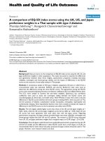
The 3-Omega method [12] used for measuring the ther-
mal conductivity of nanofluids is a transient method. The
device fabricated using micro electro-mechanical systems
(MEMS) technique can measure the thermal conductivity
of the nanofluid with a single droplet of the sample fluid.
Figure 4 shows the nanofluid on a quartz substrate,
which is modeled as a thermal resistance between the
heater and he ambient. The total heat generated from the
heater (Q
total
) passes through either the n anofluid layer
(Q
nf
) or the substrate (Q
sub
). The fluid-substrate interface
resistance is neglected when the thermal diffusivities of
the fluid and the substrate are similar. If ΔT
h
is the mea-
sured temperature oscillation of the heater in the pre-
sence of the nanofluid it can be shown that
˙
Q
total
=
˙
Q
sub
+
˙
Q
nf
=
T
h
F( q
sub
b)
πk
sub
+
T
h
F( q
nf
b)
πk
nf
.
(9)
The relationship between the temperature oscillation
and the heat generation rate can be expressed as,
T =
˙
Q
πk
∞
0
sin
2
κb
(κb)
2
(κ2+q2)
1/2
=
˙
Q
πk
F( qb)
,
(10)
q =
i2ωρ C
p
k
,
(11)
where Q’ is the heating power per unit length gener-
ated at the metal heater, k the thermal conductivity of
the substrate, q the complex thermal wave number, ω
the angular f requency of the input current, and r and
C
p
the substrate density and heat capacity,
respectively.
The temperature oscillation and the heat genera-
tion per unit heater length are related through
Equation 10. It follows that a simple relationship
between the temperature oscillations can be obtained
as follows:
1
T
h
=
1
T
sub
+
1
T
nf
.
(12)
ΔT
sub
is the heater temperature oscillation due to the
heat transfer in the quartz substrate alone (measured in
vacuum). The nanofluid thermal conductivity k
nf
is
obtained from a least squares fit of ΔT
nf
calculated from
Equation 10.
Microlitre hot strip devices for thermal
characterization of nanofluids
A simple device based on the transient hot strip (THS)
method used for the investigations of nanofluids of
volumesassmallas20μL is reported in the literature
by Casquillas et al. [13]. In this method, when the strip,
in contact with a fluid of interest is heated up by a
Figure 3 Construction of the test cell used by Das et al. [11].
Thomas and Balakrishna Panicker Sobhan Nanoscale Research Letters 2011, 6:377
/>Page 4 of 21
constant current, the temperature rise of the strip is
monitored. Photolithography patterning of the strip
was done using AZ5214 Shipley resist spin coated on a
glass substrate. Electron beam evaporation deposition
of Cr (5 nm)/Pt (50 nm)/Cr (5 nm) sandwich layer was
followed by deposition of SiO
2
(200 nm) cover layer
deposition by PECVD (plasma enhanced chemical
vapor deposition). The electrical contact areas of the
sample were obtained by photolithography and reactive
ion etching of S iO
2
layer with SF6 plasma, followed by
chromium etching. The micro-reservoir for nanofluids
was fabricated by soft lithography. The PDMS (polydi-
methylsiloxane) cover block was created from a 10:1
mixture of PDMS-curing agent. The PDMS was
degassed at room temperature for 2 h and cured at 80°
Cfor3h.APDMSblockof20mmlong,10mm
large, and 3 mm thick was cut and a 5 mm diameter
hole was drilled in the center for liquid handling. The
PDMS block and the glass substrates were exposed to
O
2
plasma, before the device was baked at 80°C for 3
h for irreversible bonding. THS device, with a water
droplet confined in the open hole is shown in Figure
5. The current and voltage me asurements were per-
formed using a voltmeter (Agilent 34410A) and a func-
tion generator (Agilent 33220A) linked to a current
source. The temperature variation of the strip was
recorded by applying a constant current and monitor-
ing the resistivity change with time from which the
liquid thermal conductivity was deduced.
The transient response of the platinum strip temperature
can be described by the following expression for t >0.2s:
T = T
o
+ α
f
ln
(
t
)
,
(13)
where T
o
is the i ntercept on the temperature axis of
the T vs. ln(t) graph. The thermal diffusivity, a
f
depends
on the thermal conductivity k, the density, and the spe-
cific heat capacity of the fluid. As a first-order approxi-
mation, it is possible to obtain the thermal conductivity
from the measurement of a
f
.
Steady state measurement using cut-bar
apparatus
Steady-state measurement of the thermal conductivity of
nanofluids using a cut-bar apparatus has bee n reported
by Sobhan and Peterson [14]. The steady state thermal
conductivity of the nanofluid can be mod eled as shown
in Figure 6. The apparatus consists of a pair of copper
rods (2.54 cm diameter) separated by an O-ring to form
the test cell as shown in Figure 7. Several thermocouples
are soldered into the copper bars to measure surface
temperatures and the heat flux. The test cell is placed in
a vacuum chamber maintained at less than 0.15 Torr.
The external convection and/or radiation losses are thus
minimized, and hence neglected. The size of the test
cell is kept small, such that convection currents do not
set in, as indicated by an estimation of the Rayleigh
number. The heat flux in the cut-bar apparatus is the
average of the heat fluxes from Equation 14 below,
Figure 4 Schematic of the experimental setup for the 3ω method reported by Oh et al. [12].
Thomas and Balakrishna Panicker Sobhan Nanoscale Research Letters 2011, 6:377
/>Page 5 of 21
calculated from the temperature differences between the
upper and lower copper bars:
q = k
co
pp
er
T
bar
/Z
bar
,
(14)
where q is the heat flux, k
copper
the thermal conductiv-
ity of copper bars, ΔT
bar
the temperature difference
along the copper bars, and ΔZ
bar
the distance along the
copper bars.
The effective thermal conductivity of the nanoparticle
suspension contained in the test cell can be calculated as:
k
eff
=[q(Z
cell
/T
cell
) − k
O-rin
g
A
O-rin
g
]/A
cell
,
(15)
where k
eff
is the effective thermal conductivity of the
nanofluid, q the heat flux, ΔT
cell
the average tempera-
ture difference between the two surfaces of the test cell,
ΔZ
cell
the distan ce between the two cell surfaces, k
O-ring
the thermal conductivity of the rubber O-ring, A
O-ring
the cross-sectional area of the rubber O-ring, and A
cell
the cross-sectional area of the test cell. Baseline experi-
ments using ethyl ene glycol and distilled water showed
an accuracy of measurement within +/-2.5%.
Comparison of thermal conductivity results
The transient hot wire (THW) method for estimating
experimentally the thermal conductivity of solids and
fluids is found to be the most accurate and reliable tech-
nique, among the methods discussed in the previous
sections. Most of the thermal conductivity measure-
ments in nanofluids reported in the literature have been
conducted using the transient hot wire method. The
temperature oscillation m ethod helps in estimating the
temperature dependent thermal conductivity of nano-
fluids. The steady-state method has the difficulty that
steady-state conditions have to be attained while per-
forming the measurements. A c omparison of the ther-
mal conductivity values of nanofluids obtained by
various measurement methods and reported in literature
is shown in Table 1.
Viscosity
Viscosity, like thermal conductivity, influences the heat
transfer behaviour of cooling fluids. Nano fluids are pre-
ferred as cooling fluids because of their improved heat
Figure 5 THS device, with a water droplet confined in the open hole, as reported in [13].
Figure 6 Heat flux paths in the steady-state measurement
method reported in Sobhan et al. [14].
Thomas and Balakrishna Panicker Sobhan Nanoscale Research Letters 2011, 6:377
/>Page 6 of 21
removal capabilities. Since most of the cooling methods
used involv e forced circu lation of the coolant, modifica-
tion of properties of fluids which can result in an
incre ased pumping power requirement could be critical.
Hence, viscosity of the nanofluid, which influences the
pumping power requirements in circulating loops,
requires a close examination. Investigations [3,4,15-22]
reported in the literature have shown that the viscosity
of base fluids increases with the addition of
nanoparticles.
Praveen et al. [15] measured the viscosity of copper
oxide nanoparticles dispersed in ethylene glycol and
water. An LV DV-II+ Brookfield programmable visc-
ometer was used for the viscosity measurement. The
copper oxide nanoparticles with an average diameter of
29 nm and a particle densit y of 6.3 g/cc were dispersed
in a 60:40 (by weight) ethylene glycol and water mixture,
to prepare nanofluids with different volume
concentrations(1,2,3,4,5,and6.12%).Theviscosity
measurements were carried out in the temperature
range of -35 to 50°C. The variation of t he shear stress
with shear strain was found to be linear for a 6.12%
concentration of the nanofluid at -35°C, which con-
firmed that the fluid has a Newtonian behavior. At all
concentrations, the viscosity value was found to be
decreasing with an increase in the temperature and a
decrease in concentration of the nanoparticles. The sus-
pension with 6.12% concentra tion gave an absolute visc-
osity of around 420 centi-Poise at -35°C.
Nguyen et al. [3] measured the temperature and parti-
cle size dependent viscosity of Al
2
O
3
-water and CuO-
water nanofluids. The average particle sizes of the sam-
ples of Al
2
O
3
nanoparticles were 36 and 47 nm, and
that of CuO nanoparticles was 29 nm. The viscosity was
measured using a ViscoLab450 Viscometer (Cambridge
Applied Systems, Massachusetts, USA). The appar atus
measured viscosity of fluids based on the couette flow
created by the rotary motion of a cylindrical piston
inside a cylindrical chamber. The viscometer was having
an accuracy and repeatability of ±1 and ±0.8%, respec-
tively, in the range of 0 to 20 centi-Poise. The dynamic
viscosities of nanofluids were m easured for fluid tem-
peratures ranging from 22 to 75°C, and particle volume
fractions varying from 1 to 9.4%. Both Al
2
O
3
-water and
CuO-wat er nanofluids showed an increase in the viscos-
ity with an increase in the particle concentration, the
largest increase being for the CuO-water nanofluid. The
alumina particles with 47 nm were found to enhance
viscosity more than the 36 nm nanoparticles. At 12%
volume fraction, the 47-nm particles were found to
enhance the viscosity 5.25 times, against a 3% increase
bythe36-nmparticles.Theincreaseintheviscosity
Figure 7 Test cell for steady-state measurement of thermal
conductivity of nanofluids [14].
Table 1 Thermal conductivity values
Sl.
no.
Base fluid Nanoparticle Avg particle size
(nm)
Conc.
(vol.%)
Sonication
time (h)
Temp.
(°C)
Enhancement Method of
measurement
Uncertainty
%
1 Distilled
water
Al
2
O
3
36 10 3 27.5-34.7 1.3 times Steady state 2.5
2 Distilled
water
CuO 29 6 3 34 1.52 times Steady state 2.5
3 Distilled
water
Al
2
O
3
28.6 1 12 21-51 2-10.8% Temperature
oscillation
2.7
4 Distilled
water
Al
2
O
3
28.6 4 12 21-51 9.4-24.3% Temperature
oscillation
2.7
5 Distilled
water
CuO 38.4 1 12 21-51 6.5-29% Temperature
oscillation
2.7
6 Distilled
water
CuO 38.4 1 12 21-51 14-36% Temperature
oscillation
2.7
7 Distilled
water
Al
2
O
3
20 1 NA 5-50 10% SHW method 1
8 Distilled
water
Al
2
O
3
45 1 15 NA 4.4% 3ω method NA
Comparison of thermal conductivity values obtained using transient and steady-state measurement techniques.
Thomas and Balakrishna Panicker Sobhan Nanoscale Research Letters 2011, 6:377
/>Page 7 of 21
with respect to the particle volume fraction has been
interpreted as due to the influence on the internal shear
stress in the fluid. The in crease in temperature has
shown to decrease the viscosities for all nanofluids,
which can be attributed to the decrease in inter-particle
and inter-molecular adhesive forces. An in teresting
observation during viscosity measurements at higher
temperatures was the hysteresis behaviour in nanofluids.
It was observed that certain critical temperature exists,
beyond which, on cooling down the nanofluid from a
heated condition, it would not trace the same viscosity
curve corresponding to the heating part of the cycle.
This was interpreted as due to the thermal degradation
of the surfactants at higher temperatures which would
result in aggl omeration of the particles. A comparison
of the viscosity values of nano fluids reported in litera-
ture [3,4,15-22] is shown in Table 2.
Forced convection in nanof luids
Forced convection heat transfer is one of the most
widely investigated thermal phenomena in nanofluids
[23-35], relevant to a number of engineering applica-
tions. Due to the observed improvement in the thermal
conductivity, nanofluids are expected to provide
enhanced convective heat transfer coefficients in con-
vection. However, as the suspension of nanoparticles in
thebasefluidsaffectthethermophysical properties
other than thermal conductivity also, such as the viscos-
ity and the thermal capacity, quantification of the influ-
ence of nanopa rticles on the heat transfer performance
is essentially required. As the physical mechanisms by
which the flow is set up in forced convection and nat-
ural convection are different, it is also required to inves-
tigate into the two scenarios individually. The case o f
the natural convection (thermosyphon) loops is another
Table 2 Viscosity values
Sl.
no.
Reference Nanoparticle used Basefluid Concentration Temp
range
Percentage enhancement in
viscosity
1 Praveen et al.
[15]
CuO (29 nm) 60:40 (in weight)
ethylene glycol
and water mixture
1, 2, 3, 4, 5, 6.12% -35 to
50°C
For 6.12% conc: 4.5 times @ 35°C and
3 times @ 50°C
2 Nguyen et al.
[3,16]
CuO (29 nm)
Al
2
O
3
(36 and 47 nm)
Water 1-12% 22 to
75°C
CuO @ 9%: 7-10 times
Al
2
O
3
(36 nm) @ 9%: 4.5-3.5 times
Al
2
O
3
(47 nm) @ 9%: 5.4-4.4 times
3 Chen et al. [17] Titanate nanotubes (diameter
approx. 10 nm, length approx.
100 nm, aspect ratio approx. 10)
Ethylene glycol 0.5, 1.0, 2.0, 4.0,
and 8.0% by
weight
20-60°
C
@ 8%: High shear viscosity is in the
range of 10-35 m Pa s
4 Phuoc et al. [18] Fe
2
O
3
(20-40 nm) Deionized water
containing 0.2%
polymer by weight
as a dispersant.
1, 2, 3, 4% 25°C @ 2%: Infinite viscosity is 12.25 cP for
0.2% PEO (Polyethylene oxide)
surfactant, and 2.58 cP for 0.2% PVP
(Polyvinylpyrrolidone) surfactant
5 Garg et al. [19] MWCNT (multi-walled carbon
nanotube) (diameter of 10-20
nm, length of 0.5-40 μm)
Deionized water
with 0.25% by
mass of gum
Arabic
1% by mass 15
and
30°C
Viscosity of nanofluids increases with
sonication time. Beyond a critical
sonication time it decreases due to
increased breakage of CNTs
6 Murshed et al.
[20]
TiO
2
(15 nm)/Al
2
O
3
(80 nm) Deionized water
with Cetyl
Trimethyl
Ammonium
Bromide (CTAB)
surfactant (0.1 mM)
1-5% by volume - @ 5% of Al
2
O
3
viscosity increases by
82%
@ 4% of TiO
2
viscosity increases by
82%
7 Chena et al. [21] TiO
2
(25 nm) and TNT (Titanate
nanotubes) (diameter approx. 10
nm, length approx. 100 nm,
aspect ratio approx. 10)
Water, ethylene
glycol
0.1-1.8% by
volume
- @ 0.6% of water-TNT 80% increase in
viscosity
@ 1.8% EG-TNT 70% increase in
viscosity
@1.8% EG-TiO
2
20% increase in
viscosity
8 Duangthongsuk
et al. [4]
TiO
2
(21 nm) Water 0.2, 0.6, 1.0, 1.5,
and 2.0% with pH
values of 7.5, 7.1,
7.0, 6.8, and 6.5,
15, 25
and
30°C
@ 15°C for the conc. range of 0.2-2%
viscosity increases by 4-15%.
9 Lee et al. [22] Al
2
O
3
(30 ± 5 nm) Deionized water
(DI)
0.01-0.3 vol.% 21-39°
C
@ 21°C for the conc. range of 0.01-
0.3% viscosity is enhanced by 0.08-
2.9%
Comparison of viscosity enhancement in various nanofluids.
Thomas and Balakrishna Panicker Sobhan Nanoscale Research Letters 2011, 6:377
/>Page 8 of 21
problem in itself, because the characteristic of the flow
is similar to that of the forced convection loop, though
the mechanism is buoyancy drive. Some of the impor-
tant investigations on forced convection in nan ofluids
are reviewed in this section. Studies on free convection
and thermosyphon loops will be discussed in the sec-
tions to follow.
Convective heat transfer in fully developed
laminar flow
Experimental investigations on the convective heat
transfer coefficient of water-Al
2
O
3
nanofluids in fully
developed laminar flow regime have been reported by
Hwang et al. [23]. Their experimental setup consisted o f
a circular tube of diameter 1.812 mm and length 2500
mm, with a test section having an externally i nsulated
electrical heater supplying a constant surface heat flux
(5000 W/m
2
), a pump, a reservoir tank, and a cooler, as
shown in Figure 8. T-type thermocouples were used to
measure the tube wall temperatures, T
s
(x), and the
mean fluid temperatures at the inlet (T
m,i
) a nd the exit.
A differential pressure transducer was used to measure
the pressure drop across the test section. The flow rate
was held in the range of 0.4 to 21 mL/min. With the
measured temperatures, heat flux, and the flow rate, the
local heat transfer coefficients were calculated as follows:
h(x)=
q
T
s
(
x
)
− T
m
(
x
)
,
(16)
where T
m
(x)andh(x) are the mean temperature of
fluid and the local heat transfer coefficient. The mean
temperature of fluid at any axial location is given by,
T
m
(x)=T
m,i
+
q
P
˙
mC
p
x
(17)
where P,
˙
m
,andC
p
are the surface perime ter, the
mass flow rate, and the heat capacity, respectively.
The darcy friction factor for the flow of Al
2
O
3
-water
nanofluids was calculated using the measured pressure
drop in the pipe and plotted against the Reynolds num-
ber. The result was f ound to agree with the theoretical
value for the fully developed laminar flow obtained
from f = 64/Red, as shown in Figure 9. The measured
heat transfer coefficient for water was found to pr ovide
an accuracy of measurement with less than 3% error
when compared to the Shah equation. The convective
heat transfer coefficient for nanofluids was found to be
enhanced by around 8%, compared t o pure wate r. It
was proposed that the flattening of the fluid velo city
profile in the presence of the nanoparticles could be
one of the reasons for enhancement in the heat transfer
coefficient.
Convective heat transfer under constant wall-
temperature condition
Heris et al. [24] mea sured convective heat transfer in
nanofluids in a circular tube, subjected to a constant
wall temperature condition. The test section consisted
of a concentric tube assembly of 1 m length. In this, the
inner copper tube was of 6 mm diameter and 0.5 mm
thickness, and the outer stainless steel tube was of 32
mm diameter, which was externally insulated with fiber
glass. The experimental setup is shown schemati call y in
Figure 10. The constant wall temperature condi tion was
Figure 8 Experimental setup of Hwang et al. [23].
Thomas and Balakrishna Panicker Sobhan Nanoscale Research Letters 2011, 6:377
/>Page 9 of 21
Figure 9 Variation of the friction factor for water-based nanofluids in fully developed laminar flow, as given by Hwang et al. [23].
Figure 10 Experimental setup of Heris et al. [24].
Thomas and Balakrishna Panicker Sobhan Nanoscale Research Letters 2011, 6:377
/>Page 10 of 21
maintained by passing saturated steam through the
annular section. The nanofluid flow rate was controlled
by a reflux line with a valve. K-type thermocouples were
used to measure the wall temperatur es (T
w
)andbulk
temperatures of the nanofluid at the inlet and the outlet
( T
b1
and T
b2
). A manometer was used to m easure the
pressure drop alo ng the test section. From a measure-
ment of the time required to fill the glass vessel, the
flow rate was calculated. The uncertainties associated
with the measurement of the temperature and the flow
rate measurements were found to b e 1.0 and 2.0%,
respectively. The convective heat transfer coefficient and
the Nusselt number were calculated as follows:
h
nf
(exp) =
C
p
nf
.ρ
nf
.U.A( T
b2
− T
b1
)
πDL(T
w
− T
b
)
LM
,
(18)
Nu
nf
(exp) =
h
nf
(exp) · D
k
,
(19)
where (T
w
- T
b
)
LM
is the logarithmic mean tempera-
ture difference, A, D,andL cross-sectional area, dia-
meter, and heated length of the pipe and
U
is the
average flow velocity. The uncertainties of the calculated
heat transfer coefficient, pressure drop, Peclet number,
Nusselt number, and Reynolds number were 3, 3, 3, 4,
and 2.5%, re spectively. The conv ective heat transfer
coefficient was measured for nanofluids in the laminar
flow regime at constant wall temperature condition, for
thevolumeconcentrationintherangeof0.2to2.5%.
The experimental results were compared with the Sie-
der-Tate correlation. Addition of nanoparticles showed
a deviation from the values obtained by the correlation,
which was particularly significant at higher values of the
Peclet number. Typically, at a Peclet number of 6000,
the heat tran sfer coefficient was found to be enhanced
by 1.16 times for 0.2% concentration and 1.41 times for
2.5% concentration.
Convective heat transfer in thermally developing
region
Anoop et al. [25] investigated the effect of the size of
nanoparticles on force d convection heat transfer in
nanofluids, focusing the study on the thermally develop-
ing region. The experimental forced circulation loop
consisted of a pump, a heated test section (copper tube,
1200 mm length, 4.75 ± 0.05 mm inner diameter, 1.25
mm thickness), a cooling section, and a collecting tank,
as shown in Figure 11. A constant laminar flow rate was
maintained in the loop. A variable transformer con-
nected to the electric circuit of the pump was used to
vary the flow rates. The DC power source connected to
the electrically insulated Ni-Cr wire, uniformly wound
around the pipe dissipated a maximum power of 200
W. T-type thermocouples were used to measure the
wall temperatures as well as the fluid inlet and exit
temperatures.
Plug flow was maintained at the entrance using a ser-
ies of wire meshes. A precise measuring jar and stop
watch is used to measure the flow rates. The local heat
transfer coefficient and local Nusselt number are defined
by Equations 16, 17, and 19. The thermal c onductivity
value used was at the bulk mean temperature. The den-
sity and specific heat of the nanofluid dependent on the
Figure 11 Experimental setup of Anoop et al. [25].
Thomas and Balakrishna Panicker Sobhan Nanoscale Research Letters 2011, 6:377
/>Page 11 of 21
volume fraction, , was given by,
ρ
nf
=(1− ϕ)ρ
bf
+ ϕρ
p
,
(20)
(ρC
p
)
nf
=(1− ϕ)(ρC
p
)
bf
+ ϕ(ρC
p
)
p
.
(21)
The convective heat transfer coefficient was measured
with nanofluids mixed with Al
2
O
3
nanoparticle s of aver-
age sizes 45 and 150 nm. In the developing flow region
and for a Reynolds number of 1500, the 45-nm sized
particles gave 25% enhancement in heat transfer com-
pared with 11% by the 150-nm particles, for a concen-
tration of 4% by weight, as shown in Figure 12. The
enhancement in heat transfer coefficient was also found
to decrease , from the develo ping to fully developed
region. For a concentration of 4% (by weight) of 45 nm
part icles and an approximate Reynolds number of 1500,
the enhancement in heat transfer coefficient was 31% at
x/D = 63, while it was 10% at x/D = 244. The uncer-
tainty in the measurement of thermal conductivity was
found to be less than 2%, and that for viscosity was
0.5%. A systematic uncertainty analysis yielded the maxi-
mum error in the R eynolds number and the Nus selt
number to be around 3.24 and 2.45%, respectively.
Single-phase and two-phase heat transfer in
microchannels
Lee et al. [26] investigated on the use of nanofluids for
single-phase and two-phase heat transfer in microchan-
nels. The experimental setup used for the measurements
is shown in Figure 13. The channels were fabricated by
milling rectangular grooves, 215 μmwideand821μm
deep, into the top surface of an oxygen-free copper
block. The block was inserted into a G-7 plastic housing
and sealed on top with a polycarbonate cover plate. The
method produced 21 parallel microchannels, each with a
hydraulic diameter of 341 μm, occupying a total sub-
strate area with 1 cm width and 4.48 cm length. Heating
was provided by 12 cartridge heaters embedded in the
bottom of the copper block. The fluid temperature and
pressure were measured at the inlet and exit plenums of
the housing. T he bottom wall temperature was also
measured using K-type thermocouples inserted along
the flow direction. A Yokogawa WT210 power meter
was used to measure the electric power input to the
copper block. A bypass was included immediately down-
stream of the flow-meters to calibra te the flow meters.
An HP 3852A data acquisition system was utilized in
the setup. Heat loss from the copper block was esti-
mated as less than 5% of the electrical power input. The
single phase flow experiments in the laminar regime
showed an enhancement in heat transfer with the nano-
particle concentration. The fluid and pipe wall tempera-
tures were found to increase with the nanoparticle
concentration, which was interpreted as due to the
reduced specific heat of nanofluids. The enhancement in
heat transfer was found to be lesser in the turbulent
flow regime than in the laminar regime. In the case of
two phase heat transfer using nanofluids, it was
observed that the chances of particles separating, getting
deposited as clusters and thus clogging passages in
micro-channels could make the method less preferable.
Figure 12 Variation of heat transfer coefficient with particle size and Reynolds number as given by Anoop et al. [25].
Thomas and Balakrishna Panicker Sobhan Nanoscale Research Letters 2011, 6:377
/>Page 12 of 21
Convective heat transfer in confined laminar
radial flows
Impinging jets with or without confinement as wel l as
fluid flow between fixed or rotating disks with axial
injection have applications in turbo machine ry and loca-
lized cooling. Gherasim at al. [27] expe rimentally inves-
tigated the heat transfer enhancement capabilities of
coolants with Al
2
O
3
nanoparticles suspended in water
inside a radial flow cooling system. The test rig was as
shown i n Figure 14. Parametric studies were performed
on heat transfer inside the space delimited by the nozzle
and the heated disk (Aluminum, 30 cm diameter, 7.5
cm thick), with and adjustable separating distance
between them. The disk was heated with seven symme-
trically implanted 200 W cartridge heating elements,
one at t he center of the disk, and the other six spaced
at 60° from each other at approximately half the radial
distance. Thermally insulated K-type thermocouples
were used to measure the temperatures. The heated disk
was insulated using a 1.5-cm Teflon disk and a 3-cm
thick insulating foam board. The periphery of the test
section was surrounded by insulating foam. The con-
centric inlet and outlet tubes were insulated from each
otherusingaplasticsleeveandalayerofair.Fromthe
time required to accumulate a certain quantity of fluid,
the fluid mass flow rate was c alculated. The heat flux
was varied by changing the tension applied to the heat-
ing elements. The applied power was calculated from
the measured voltage and current. The Reynolds num-
ber, as defined in Equation 22, and the Nusselt number
(Equation 19) were calculated:
Re =
U
inlet
· D
h
· ρ
nf
μ
nf
,
(22)
where
U
inl
et
is the mean inlet fluid vel ocity and D
h
is
given by 2δ, where δ is the distance separating the disks.
The local heat transfer coefficient h
r
is obtained as:
h(r)=
q
T
w
,
r
− T
b
,
r
.
(23)
The bulk temperature at a given radial section (T
b,r
)
was calculated as:
T
b,r
− T
b,i
=
q
πr
2
˙
mC
p
,
(24)
where T
b,r
and T
b,i
are the bulk temperatures at a
given radius and at the inlet.
Figure 13 Experimental setup of Lee et al. [26].
Figure 14 Experimental setup of Gherasim et al. [27].
Thomas and Balakrishna Panicker Sobhan Nanoscale Research Letters 2011, 6:377
/>Page 13 of 21
Considering all the uncertainties on experimental
measurements, the average relative errors on Nusselt
number calculations were estimated as 12.1, 11.5, and
11% for cases with particle volume concentrations of 2,
4, and 6%, respectively. The experiments were aimed at
investigating the effect of nanofluids in a steady laminar
flow between the disk and a flat plate, with axial entry
and radial exit. The heat transfer coefficient was found
to increase with the particle concentration and the flow
rate and decrease with an increasing gap between disks.
Summary
A review of the important investigations on forced con-
vection heat transfer in nanofluids, presented above
reveals the following general inferences. Though not
extensively, attention has been devoted to explore the
fluid dynamic and thermal performance of nanofuids
under various physical situations. Convective heat trans-
fer studies have been carried out in the developing
region [25,34] as well as under fully developed condi-
tions [15]. Studies have been reported pertaining to
laminar [23,24,27-29], transition [32,35], and turbulent
[28,33] regimes of flow. Single phase and two phase
flows have been analyzed with axial and radial flow
directions [27]. Constant heat flux [25,28] and constant
temperature [24,29] boundary conditions have been
investigated. Studies have also been reported on flow
and heat transfer in compact passages such as micro
channels [26,30]. A comparison of the convective heat
transfer coefficients for different nanofluids at various
flow and heat transfer conditions reported in the litera-
ture [23-35] is shown in Table 3.
Almost all of the above investigations have shown that
the performance of nanofluids in fo rced convection heat
transfer is better than that of the base fluid. However,
there have been studies which reported deterioration in
convectiv e heat transfer in ethylene glycol based titanate
nanofluids [31]. It generally is noticed that the percen -
tage enhancement in heat transfer is much more than
the individual enhancement in thermal conductivity.
This fact is often attributed to the effect of the disrup-
tion of the thermal boundary layer due to particle move-
ment [25].
The enhancement of heat transfer capabilities of fluids
results in accomplishing higher heat transfer rates with-
out incorporating any modifications to existing heat
exchangers. It also effectively leads to a reduction in the
pumping power requirements in practic al applications,
as a lower flow rate will produce the required amount
of heat transfer. These, in general makes the use of
nanofluids for forced circulation loops attractive, leading
to better performance and the resulting a dvantage in
energy efficiency.
Natural convection loops using nanofluids
Many of the investigations o n natural convection phe-
nomena in nanofluids deal with stagnant columns of the
liquid, a nd in these studies, a possibility of reduction of
the heat transfer coefficient has been observed [36].
Some investigators have discussed on the reasons for
this behavior, and have suggested that this may be due
to the reduction in the gradients of temperature within
the fluid, resulting from the enhancement of the fluid
thermal conductivity. However, natural circulation loops
present a different scenario compared to convection in
liquid columns, as the circulation is developed due to
thermosyphon effect. It is of interest to look into some
of the investigation s on n atural circulation loops with
nanofluids, and understand the heat transfer perfor-
mance under the influence of the nanoparticles. A few
important articles on this topic are reviewed below.
Some investigations on natural convection in stagnant
fluid columns and pool boiling heat transfer are also
reviewed.
Noie et al. [37] reported an enhancement in heat
transfer when nanofluids were used in a two-phase
closed thermosyphon ( TPCT). The TPCT was made of
a copper tube (20 mm internal diameter, 1 mm thick,
1000 mm long) and, the evaporator (300 mm long)
and condenser (400 mm long) sections. Heating was
provided by a Nickel-Chrome wire electric heater
wound around the evaporator section, with a nominal
powerof1000W.Theexperimentalsetupwasas
showninFigure15.
The input power is given by:
Q
in
= VI −
Q
loss
,
(25)
where Q
loss
is the total heat loss from the e vaporator
section by radiation and free convection:
Q
loss
=
Q
rad
+
Q
con
v
(26)
The radiation and free convection heat transfer rates
were calculated as follows:
Q
rad
= εAσ
(
T
ins
4
− T
surr
4
)
(27)
Q
conv
= h
conv
.A
(
T
ins
− T
surr
).
(28)
Intheabove,thefreeconvectionheattransfercoeffi-
cient was determined using the expression:
Nu =
h
conv
· L
t
k
surr
=
⎧
⎪
⎪
⎪
⎪
⎪
⎨
⎪
⎪
⎪
⎪
⎪
⎩
0.825 +
0.387 · Ra
1/6
1+
0.492
Pr
9/16
8/27
⎫
⎪
⎪
⎪
⎪
⎪
⎬
⎪
⎪
⎪
⎪
⎪
⎭
2
.
(29)
Thomas and Balakrishna Panicker Sobhan Nanoscale Research Letters 2011, 6:377
/>Page 14 of 21
Table 3 Convective heat transfer coefficient and frictional effects
Sl.
no.
Reference Nanoparticle Base fluid Flow regime Wall
boumdary
condition
Concentration Enhancement in heat transfer coefficient Pressure drop/friction
factor
1 Hwang et al.
[23]
Al
2
O
3
(30 ± 5 nm) Water Fully developed
laminar flow with
Constant
heat flux
0.01-0.3 vol.% @ Re = 700 for 0.3%, heat transfer coeff., h
increases by 8%
Friction factor follows f
= 64/Re
D
2 Heris et al. [24] Al
2
O
3
Water Laminar, Re:700-
2050
Constant
wall temp.
0.2, 0.5, 1.0, 1.5, 2.0,
2.5% volume
@ Peclet no., Pe = 6000 for 2.5%, h increases
by 41%
ΔP = 200 Pa/m @ Re =
700
ΔP = 700 Pa/m @ Re =
2000
3 Anoop et al.
[25]
Al
2
O
3
(45 and 150 nm) Water Laminar thermally
developing flow
Constant
heat flux
1, 2, 4, and 6 wt% @ x/D = 147, Re = 1550 and 4%, for 45 nm h
increases by 25% and for 150 nm h increases
by 11%
-
4 Lee et al. [26] Al
2
O
3
(36 nm) Water Laminar flow in
microchannels,
Re
Dh
= 140-941
Constant
heat flux
1, 2% by volume @ Q = 300 W, Re = 800 for 2%, h increases by
17%
@ Re = 800
ΔP = 21000 Pa for 2
vol.%
ΔP = 15000 Pa for
water.
5 Gherasim et al.
[27]
Al
2
O
3
(47 nm) Water Laminar radial
flow
Constant
heat flux
2, 4, and 6% by
volume
@q“ = 3900 W/m
2
, disk spacing of 2 mm and
Re = 500 for 4%, heat transfer is doubled
-
6 Kim et al. [28] Al
2
O
3
(20-50 nm), amorphous
carbonic nanofluids (20 nm)
Water Laminar and
turbulent flows
Constant
heat flux
Amorphous carbonic
nanofluids @3.5 vol.
%, Al
2
O
3
nanofluids
@3 vol.%.
@x/D = 50, Re = 1460 for 3% Al
2
O
3
, h
increases by 25%
@x/D = 50, Re = 6020 for 3% Al
2
O
3
, h
increases by 15%
-
7 Heris et al. [29] CuO (50-60 nm), Al
2
O
3
(20
nm)
Water Laminar flows Constant
wall temp.
0.2-3 vol.% @Pe = 6500 for 3% Al
2
O
3
Nu = 8.5
@Pe = 6500 for 3% CuO Nu =8
-
8 Jung et al. [30] Al
2
O
3
(170 nm) Water,
Water-
Ethylene
glycol
50:50
Laminar flow in
rectangular
microchannel
Constant
heat flux
0.6, 1.2, 1.8% by
volume
@x/D =0,Re = 284 for 1.8% in water, h
increases by 40%.
@x/D =0,Re = 32 for 1.8% in water-EG, h
increases by 14%.
Friction factors
comparable with that
of water
9 Ding et al. [31] Titanate (20 nm), CNT,
titanate nanotubes (d =10
nm and l = 100 nm), nano
diamond (2-50 nm)
Water Thermally
developing
laminar and
turbulent flow
Constant
heat flux
0-4 vol.% Heat transfer deteriorates for ethylene glycol-
based titania and aqueous-based nano-
diamond nanofluids. Water-CNT nanofluids
give max enhancement
10 Sharma et al.
[32]
Al
2
O
3
(47 nm) Water Hydrodynamically
and thermally
developed
Transition flow.
Constant
heat flux
0.02, 0.1% by volume For 0.1% in the range of Re = 3500-8000 heat
transfer enhanced by 14-24%
-
11 Duangthongsuk
et al. [33]
TiO
2
(21 nm) Water Turbulent flow,
Re-4000-17000
Double pipe
counter flow
heat
exchanger
0.2 vol.% h increases by 6-11% for the flow range of Re
= 4000-17000
Pressure drop and
friction factor of the
nanofluid are close to
those of water
12 Ding et al. [34] MWCNT Water Laminar flow Cosntant
heat flux
0.1, 0.25, and 0.5% by
volume
@x/D = 150, Re = 1200 for 0.1% h increases
by 150%
-
13 Yu et al. [35] SiC (170 nm) Water Re = 3300-13000 Constant
heat flux
3.7 vol.% @Re = 10000 h is enhanced by 60% The pumping power
penalty for SiC-water is
lesser than for Al
2
O
3
-
water
Comparison of enhancement of heat transfer coefficient and frictional effects in various nanofluids.
Thomas and Balakrishna Panicker Sobhan Nanoscale Research Letters 2011, 6:377
/>Page 15 of 21
The total heat loss was estimated to be about 2.49% of
the input power to the evaporator section. As shown in
Figure 15, LM35 thermocouples were mounted on the
TPCT, evaporator section, adiabatic section, and con-
denser section. Precise thermometers were used in the
condenser section to read the input and output tem-
perature of the coolant water. All the measured data
were monitored using a data acquisition system. The
quantity of heat transferred to the coolant water was
calculated as:
Q
out
= mC
p
(T
out
− T
in
)
.
(30)
The efficiency of the TPCT was expressed as a ratio of
theoutputheatbycondensationtotheinputheatby
evaporation:
η =
Q
out
Q
in
.
(31)
Considering the measurement errors of the para-
meters such as the current, the voltage, the inlet and
outlet temperature of cooling water, and the mass flow
rate, and neglecting the effec t of Q
loss
,themaximum
uncertainty of the e fficiency was calculated as 5.41%.
Figure 16 shows that the efficiency of TPCT increases
with nanoparticle concentration at all input power. For
an input power of 97.1 W, the 1% nanofluid gives an
efficiency of 85.6% as compared to 75.1% given by pure
water.
Nayak et al. [38] investigated the single phase natural
circulation behavior of nanofluid s in a rectangular loop.
The test facility was made of glass tubes with 26.9 mm
inner diameter, and had a heating section at the bottom
and a cooling section at the top, as shown in Figure 17.
Thevolumetricexpansionofthefluidwasaccommo-
dated by the expansion tank which also ensured that the
loop remains full of water. Thermocouples were used to
measure the instantaneous local temperature, and a
pressure transducer installed in the horizontal leg of the
loop measured the flow rate. The loop was insulated to
minimize the heat losses to the ambient. The measure-
ment accuracy was 0.4% (+1.1°C) for the thermocouples,
Figure 15 Experimental setup of Noie et al. [37].
Thomas and Balakrishna Panicker Sobhan Nanoscale Research Letters 2011, 6:377
/>Page 16 of 21
Figure 16 Variation of efficiency of TPCT with nanoparticle concentration and input power as given by Noie et al. [37].
Figure 17 Experimental setup of Nayak et al. [38].
Thomas and Balakrishna Panicker Sobhan Nanoscale Research Letters 2011, 6:377
/>Page 17 of 21
+0.25% for the flow rate measurement and +0.5% of the
range (0 to 1250 W) for power and pressure drop (-100
to +100 Pa). Experimental results have shown that the
steady-state flow rate of nanofluids in the thermosyphon
loop is higher compared to pure water. The flow rate is
increased by 20 to 35% depe nding on the nanopartic le
concentration and the heat input.
Khandekar et al. [39] reported investigations on the
thermal performance of a closed two-phase thermosy-
phon system, using pure water and various water-
based nanoflu ids of Al
2
O
3
,CuO,andlaponiteclayas
working fluids. The setup shown i n Figure 18 has a
pressure transducer fitted to the thermosyphon to
monitor proper initial vacu um level and su bsequent
saturation pr essure profiles. Fou r mica insulated sur-
face heaters (116 mm × 48 mm) were mounted on the
outer surface of a copper heating block (120 mm × 50
mm × 50 mm) with a center bore to accommodate the
thermosyphon container which acts as the evaporator.
Thefinnedtubecondenserwasmadeof40square
copper fins (70 mm × 70 mm × 1 mm), brazed at a
pitch of 6.5 mm. The inlet and outlet of the shell side
were designed so as to produce cross-flow conditions
over the condenser fins. K -type thermocouples were
used to measure the temperature at important axial
locations on the thermosyphon tube. A PC based data
acquisition system (NI-PCI-4351, National Instru-
ments) was used to acquire the data.
The thermal resistance is defined as:
R
th
=(T
e
− T
c
)
˙
Q,
(32)
where T
e
and T
c
are average values of the tempera-
tures measured by the thermocouples.
The basic mec hanisms of hea t transfer, in a gravity-
assisted thermosyphon, are nucleate pool boiling in the
evaporator and film-wise condensation in the condenser
secti on [14]. The boiling and cond ensation heat transfer
rates are influence d by the thermophysical properties of
the working fluid and the characteristic features of the
solid substrate. Major limitations of the gravity assisted
thermosyphon are the dry-out limitation, counter cur-
rent flow limitation (CCFL) or flooding, and the boiling
limitation. It was noticed that if the filling ratio (FR) is
more than 40%, dry out phenom enon is not observed
and the maximum heat flux is limited by the CCFL/
flooding or the boiling limitation (BL).
The thermal performance of the system was found to
be deteriorating when nanofluids were used as working
fluids. The deterioration was maximum with laponite
and minimum for aluminum oxide suspended nano-
fluids. Increased thermal conductivity of the nanofluids
showed no effect on t he nucleate pool boiling heat
transfer coefficient. It was suggested that phys ical inter-
action of nanoparticles with the nucleating cavities has
been influencing the boiling characteristics of the nano-
fluids. The deterioration of the thermal performa nce of
the nanofluid in closed two-phase thermosyphon was
attributed to the improvement in wettability due to
entrapment of nanopartic les in t he grooves present on
the surface. Improv ed critical heat flux values were also
observed, which effect was also attributed to the
increased wettability characteristics of nanofluids.
Natural convection heat transfer is a preferred mode
as it is comparatively noise less and does not have
pumping power requirement. The use of Al
2
O
3
/water
nanofluids in closed two-phase thermosyphon systems
[37] has shown to increase its efficiency by 14.7% when
compared to water. In rectangular loops [38] with
water-based nanofluids, the flow instabilities were found
to decrease and the circulation rates improved, com-
pared to the base fluid. At the same time, there have
been observations [39] that in two-phase thermosyphon
loops, water-based nanofluids with suspended metal oxi-
des h ave inferior thermal performance compared to the
base fluids, which was explained as due to the increased
surface wettability of nanofluids.
Studies in stagnant columns
Experimental investigations have been reported on nat-
ural convection in stagnant columns, as well as pool
boiling heat transfer in nanofluids. Measurement of
Figure 18 Experimental setup of Khandekar et al. [39].
Thomas and Balakrishna Panicker Sobhan Nanoscale Research Letters 2011, 6:377
/>Page 18 of 21
critical heat flux (CHF) has also been reported in pool
boiling.
Putra et al. [40] experimentally investigated the nat-
ural convection inside a horizontal cylinder heated from
one side and cooled from the other. The effects of the
particle concentration, the material of the particles, and
the geometry of the containing cavity on natural convec-
tion were investigated. A systematic and definite dete-
rioration of natural convection was observed and the
deterioration increased with particle concentration. Cop-
per oxide nanofluids showed larger deterioration than
aluminum oxide nanofluids. With 4% Al
2
O
3
concentra-
tion, an L/D ratio of 1.5 showed a higher value of Nus-
selt number compared to an L/D ratio of 0.5.
Liu et al. [41] studied the boiling heat transfer charac-
teristics of nanofluids in a flat heat pipe evaporator with
a micro-grooved heating surface. The nucleate boiling
heat transfer c oefficient and CHF of water-CuO nano-
fluids at differe nt operating pressures and particle con-
centrations were measured. For a nanoparticle mass
concentration less than 1%, the heat transfer coefficient
and CHF were found to increase. Above 1% by weight,
the CHF was almost constant and the heat transfer coef-
ficient deteriorated. This was explained to be due to a
decrease in the surface roughness and the solid-liquid
contact angle. Heat tra nsfer coefficient and CHF of
nanofluids were found to increase with a reduc tion in
the pre ssure. At the atmospheric press ure, the heat
transfer coefficient and CHF showed 25 and 50%
enhancement, respectively, compared to 150 and 200%
enhancement at a pressure of 7.4 kPa.
Boiling heat transfer on a high-temperature silver
sphere immersed in TiO
2
nanofluid was investigated by
Lotfi et al. [42]. A 10 mm diameter silver sphere heated
to 700°C was immersed in the nanofluid at 90°C to
study the boiling heat transfer and quenching capabil-
ities. Film boiling heat flux in the TiO
2
nanofluid was
found to be low er than that in water. The accumulation
of nanoparticles at the liquid-vapor interface was found
to reduce the vapor removal rate from the film, creating
a thick vapor film barrier which reduced the minimum
film boiling heat flux. Experiments by Narayan et al.
[43] showed that surface orientation has an influence on
pool boiling heat transfer in nanoparticle suspensions. A
smooth heated tube was suspended at different orienta-
tions in nanofluids to study the pool boiling perfor-
mance. The pool boiling heat transfer was found to be
maximum for the horizontal inclination. Al
2
O
3
-water
nanofluids of 47 nm particles and 1% by weight concen-
tration showed enhancement in pool boiling heat trans-
fer performance, over that of water. With increase in
concentration and particle size, the performance
decreased for nanofluids. For vertical and 45° inclination
orientations, nanofluids showed inferior performance
compared to pure water. Coursey and Kim [44] investi-
gated the effect of surface wettability on the boiling per-
formance of nanofluids. In the experiments, heater
surfaces altered to varying de grees by oxidization or by
depositing metal were investigated by measuring the
surface energy measurements and b oiling heat transfer
(CHF). It was found that the CHF of poorly wetting sys-
tems could be improved by up to 37% by the use of
nanofluids, while surfaces with good wetting characteris-
tics showed less improvement.
Conclusion
Suspending nanoparticles in base fluids has proven to
show considerable effects on various thermophysical
properties, which influences the heat transfer perfor-
mance. This article focused on some of the recently
reported investigations on convective heat transfer and
phase change in nanofluids. It also presented some dis-
cussions on the experimental techniques employed to
measure the effective thermal conductivity, as well as to
characterize the thermal performance of s ystems invol-
ving nanofluids.
The thermal conductivity of nanofluids has been mea-
sured using transient and steady-state methods, of
which the transient ho t wire method is found to b e
more versatile, accurate, a nd reliable. A review of the
important investigations on forced convection heat
transfer at various flow and heat transfer conditions
have shown that the performance of nanofluids in
forced convection is better than that of the base fluid. It
has also been noticed that the percentage enhancement
in heat transfer is much more than the individual
enhancement in thermal conductivity.
The use of nanofluids in thermosyphon loops has
shown an increase in the efficiency, a decrease in flow
instabilities, and an increase in the flow rates. There
have also been observations that in two-phase thermosy-
phon loops, the increased wettability of nanofluids may
adversely affect the thermal performance compared to
that of the base fluid.
Investigation on the natural convection inside a hori-
zontal cylinder heated from one side and cooled from
the other has shown deterioration in heat transfer while
nanofluids are used. At low nanoparticle mass concen-
trations, the CHF was found to increase in a flat heat
pipe. In pool boiling heat transfer in nanoparticle sus-
pensions, the orientation of the heater surface is found
to have an influence on the heat transfer rate, the maxi-
mum being for horizontal orientation. It has been
noticed that for poorly wetting surfaces, the CHF can be
increased by the use of nanofluids.
Of the various applications proposed, the use of nano-
fluids in closed circulation loops for sensible heat
removal is found to be the most attractive, and these
Thomas and Balakrishna Panicker Sobhan Nanoscale Research Letters 2011, 6:377
/>Page 19 of 21
can become part of steady-state heat exchange systems.
The enhancement of the heat transfer capability of fluids
with suspended nanoparticles makes their use in con-
vection loops and thermosyphons an inter esting option,
leading to better system performance and the resulting
advantage in energy efficiency.
Abbreviations
BL: boiling limitation; CCFL: counter current flow limitation; CHF: critical heat
flux; MEMS: micro electro-mechanical systems; PDMS: polydimethylsiloxane;
PECVD: plasma enhanced chemical vapor deposition; POM:
polyoxymethylene; SHW: short hot wire; THS: transient hot strip; TPCT: two-
phase closed thermosyphon.
Authors’ contributions
ST compiled the studies conducted on thermal conductivity, viscosity, free
and forced convection and boiling phenomena, compared and analysed the
results.
CBS contributed in conceptualizing the manuscript and revising it critically
for improving technical contents.
Competing interests
The authors declare that they have no competing interests.
Received: 13 January 2011 Accepted: 9 May 2011 Published: 9 May 2011
References
1. Lee S, Choi US, Li S, Eastman JA: Measuring thermal conductivity of fluids
containing oxide nanoparticles. ASME J Heat Transf 1999, 121:280-289.
2. Xie H, Wang J, Xi T, Liu Y, Ai F: Thermal conductivity enhancement of
suspensions containing nanosized alumina particles. J Appl Phys 2002,
91:4568-4572.
3. Nguyen CT, Desgranges F, Roy G, Galanis N, Mare T, Boucher S, Angue
Mintsa H: Temperature and particle-size dependent viscosity data for
water-based nanofluids - Hysteresis phenomenon. Int J Heat Fluid Flow
2007, 28:1492-1506.
4. Duangthongsuk W, Wongwises S: Measurement of temperature-
dependent thermal conductivity and viscosity of TiO
2
-water nanofluids.
Exp Therm Fluid Sci 2009, 33:706-714.
5. Sobhan CB, Sankar N, Mathew N, Ratnapal R: Molecular dynamics
modeling of thermal conductivity of engineering fluids and its
enhancement using nanoparticles. CANEUS 2006 Micro-Nano Technology
for Aerospace Applications Toulouse, France; 2006.
6. Sankar N, Mathew N, Sobhan CB: Molecular dynamics modeling of
thermal conductivity enhancement in metal nanoparticle suspensions.
Int Commun Heat Mass Transf 2008, 35:867-872.
7. Pantzali MN, Kanaris AG, Antoniadis KD, Mouza AA, Paras SV: Effect of
nanofluids on the performance of a miniature plate heat exchanger
with modulated surface. Int J Heat Fluid Flow 2009, 30:691-699.
8. Nguyen CT, Roy G, Gauthier C, Galanis N: Heat transfer enhancement
using Al
2
O
3
- water nanofluid for an electronic liquid cooling system.
Appl Therm Eng 2007, 27:1501-1506.
9. Xie HQ, Gu H, Fujii M, Zhang X: Short hot wire technique for measuring
thermal conductivity and thermal diffusivity of various materials. Meas
Sci Technol 2006, 17:208-214.
10. Zhang X, Gu H, Fujii M: Effective thermal conductivity and thermal
diffusivity of nanofluids containing spherical and cylindrical
nanoparticles. Exp Therm Fluid Sci 2007, 31:593-599.
11. Das SK, Putra N, Thiesen P, Roetzel W: Temperature dependence of
thermal conductivity enhancement for nanofluids. ASME J Heat Transf
2003, 125:567-574.
12. Oh DW, Jain A, Eaton JK, Goodson KE, Lee JS: Thermal conductivity
measurement and sedimentation detection of aluminum oxide
nanofluids by using the 3ω method. Int J Heat Fluid Flow 2008,
29:1456-1461.
13. Casquillas GV, Berre ML, Peroz C, Chen Y, Greffet JJ: Microlitre hot strip
devices for thermal characterization of nanofluids. Microelectron Eng 2007,
84:1194-1197.
14. Sobhan CB, Peterson GP: Microscale and Nanoscale Heat Transfer
Fundamentals and Engineering Applications Boca Raton: Taylor and Francis/
CRC Press; 2008.
15. Praveen KN, Devdatta PK, Misra D, Das DK: Viscosity of copper oxide
nanoparticles dispersed in ethylene glycol and water mixture. Exp Therm
Fluid Sci 2007, 32:397-402.
16. Nguyen CT, Desgranges F, Roy G, Galanis N, Mare’ T, Boucher S, Angue
Mintsa H: Viscosity data for Al
2
O
3
-water nanofluid–hysteresis: is heat
transfer enhancement using nanofluids reliable? Int J Therm Sci 2008,
47:103-111.
17. Chen H, Ding Y, Lapkin A: Rheological behaviour of nanofluids containing
tube/rod-like nanoparticles. Powder Technol 2009, 194:132-141.
18. Phuoc TX, Massoudi M: Experimental observations of the effects of shear
rates and particle concentration on the viscosity of Fe
2
O
3
-deionized
water nanofluids. Int J Therm Sci 2009, 48:1294-1301.
19. Garg P, Alvarado JL, Marsh C, Carlson TA, Kessler DA, Annamalai K: An
experimental study on the effect of ultrasonication on viscosity and
heat transfer performance of multi-wall carbon nanotube-based
aqueous nanofluids. Int J Heat Mass Transf 2009, 52:5090-5101.
20. Murshed SMS, Leong KC, Yang C: Investigations of thermal conductivity
and viscosity of nanofluids. Int J Therm Sci 2008, 47:560-568.
21. Chena H, Witharana S, Jina Y, Kimd C, Ding Y: Predicting thermal
conductivity of liquid suspensions of nanoparticles (nanofluids) based
on rheology. Particuology 2009, 7:151-157.
22. Lee JH, Hwang KS, Jang SP, Lee BH, Kim JH, Choi SUS, Choi CJ: Effective
viscosities and thermal conductivities of aqueous nanofluids containing
low volume concentrations of Al
2
O
3
nanoparticles. Int J Heat Mass Transf
2008, 51:2651-2656.
23. Hwang KS, Jang SP, Choi US: Flow and convective heat transfer
characteristics of water-based Al
2
O
3
nanofluids in fully developed
laminar flow regime. Int J Heat Mass Transf 2009, 52:193-199.
24. Heris SZ, Esfahany MN, Etemad SGh: Experimental investigation of
convective heat transfer of Al
2
O
3
/water nanofluid in circular tube. Int J
Heat Fluid Flow 2007, 28:203-210.
25. Anoop KB, Sundararajan T, Das SK: Effect of particle size on the
convective heat transfer in nanofluid in the developing region. Int J Heat
Mass Transf 2009, 52:2189-2195.
26. Lee J, Mudawar I: Assessment of the effectiveness of nanofluids for
single-phase and two-phase heat transfer in micro-channels. Int J Heat
Mass Transf 2007, 50:452-463.
27. Gherasim I, Roy G, Nguyen CT, Vo-Ngoc D: Experimental investigation of
nanofluids in confined laminar radial flows. Int J Therm Sci 2009, 48:1486-1493.
28. Kim D, Kwon Y, Cho Y, Li C, Cheong S, Hwang Y, Lee J, Hong D, Moon S:
Convective heat transfer characteristics of nanofluids under laminar and
turbulent flow conditions. Curr Appl Phys 2009, 9:119-123.
29. Heris SZ, Etemad SGh, Esfahany MN: Experimental investigation of oxide
nanofluids laminar flow convective heat transfer. Int Commun Heat Mass
Transf 2006, 33:529-535.
30. Jung JY, Oh HS, Kwak HY: Forced convective heat transfer of nanofluids
in microchannels. Int J Heat Mass Transf 2009, 52:466-472.
31. Ding Y, Chen H, He Y, Lapkin A, Yeganeh M, Siller L, Butenko YV: Forced
convective heat transfer of nanofluids. Adv Powder Technol 2007,
18:813-824.
32. Sharma KV, Sundar LS, Sarma PK: Estimation of heat transfer coefficient
and friction factor in the transition flow with low volume concentration
of Al
2
O
3
nanofluid flowing in a circular tube and with twisted tape
insert. Int Commun Heat Mass Transf 2009, 36:503-507.
33. Duangthongsuk W, Wongwises S: Heat transfer enhancement and
pressure drop characteristics of TiO
2
-water nanofluid in a double-tube
counter flow heat exchanger. Int J Heat Mass Transf 2009, 52:2059-2067.
34. Ding Y, Alias H, Wen D, Williams RA: Heat transfer of aqueous suspensions
of carbon nanotubes (CNT nanofluids). Int J Heat Mass Transf 2006,
49:240-250.
35. Yu W, France DM, Smith DS, Singh D, Timofeeva EV, Routbort JL: Heat
transfer to a silicon carbide/water nanofluid. Int J Heat Mass Transf 2009,
52:3606-3612.
36. Chang BH, Mills AF, Hernandez E: Natural convection of microparticle
suspensions in thin enclosures. Int J Heat Mass Transf 2008, 51:1332-1341.
37. Noie SH, Heris SZ, Kahani M, Nowee SM: Heat transfer enhancement using
Al
2
O
3
/water nanofluid in a two-phase closed thermosyphon. Int J Heat
Fluid Flow 2009, 30:700-705.
Thomas and Balakrishna Panicker Sobhan Nanoscale Research Letters 2011, 6:377
/>Page 20 of 21
38. Nayak AK, Gartia MR, Vijayan PK: An experimental investigation of single-
phase natural circulation behaviour in a rectangular loop with Al
2
O
3
nanofluids. Exp Therm Fluid Sci 2008, 33:184-189.
39. Khandekar S, Joshi YM, Mehta B: Thermal performance of closed two-
phase thermosyphon using nanofluids. Int J Therm Sci 2008, 47:659-667.
40. Putra N, Roetzel W, Das SK: Natural convection of nano-fluids. Heat Mass
Transf 2003, 39:775-784.
41. Liu Z, Xiong JG, Bao R: Boiling heat transfer characteristics of nanofluids
in a flat heat pipe evaporator with micro-grooved heating surface. Int J
Multiphase Flow 2007, 33:1284-1295.
42. Lotfi H, Shafii MB: Boiling heat transfer on a high temperature silver
sphere in nanofluid. Int J Therm Sci 2009, 48:2215-2220.
43. Narayan GP, Anoop KB, Sateesh G, Das SK: Effect of surface orientation on
pool boiling heat transfer of nanoparticle suspensions. Int J Multiphase
Flow 2008, 34:145-160.
44. Coursey JS, Kim J: Nanofluid boiling: the effect of surface wettability. Int J
Heat Fluid Flow 2008, 29:1577-1585.
doi:10.1186/1556-276X-6-377
Cite this article as: Thomas and Balakrishna Panicker Sobhan: A review of
experimental investigations on thermal phenomena in nanofluids.
Nanoscale Research Letters 2011 6:377.
Submit your manuscript to a
journal and benefi t from:
7 Convenient online submission
7 Rigorous peer review
7 Immediate publication on acceptance
7 Open access: articles freely available online
7 High visibility within the fi eld
7 Retaining the copyright to your article
Submit your next manuscript at 7 springeropen.com
Thomas and Balakrishna Panicker Sobhan Nanoscale Research Letters 2011, 6:377
/>Page 21 of 21