Báo cáo hóa học: " Porous anodic alumina on galvanically grown PtSi layer for application in template-assisted Si nanowire growth" doc
Bạn đang xem bản rút gọn của tài liệu. Xem và tải ngay bản đầy đủ của tài liệu tại đây (1.27 MB, 6 trang )
NANO EXPRESS Open Access
Porous anodic alumina on galvanically grown PtSi
layer for application in template-assisted Si
nanowire growth
Irini Michelakaki
1
, Androula G Nassiopoulou
1*
, Eleni Stavrinidou
2
, Katerina Breza
2
and Nikos Frangis
2
Abstract
We report on the fabrication and morphology/structural characterization of a porous anodic alumina (PAA)/PtSi
nano-template for use as matrix in template-assisted Si nanowire growth on a Si substrate. The PtSi layer was
formed by electroless deposition from an aqueous solution containi ng the metal salt and HF, while the PAA
membrane by anodizing an Al film deposited on the PtSi layer. The morphology and structure of the PtSi layer
and of the alumina membrane on top were studied by Scanning and High Resolution Transmission Electron
Microscopies (SEM, HRTEM). Cross sectional HRTEM images combined with electron diffraction (ED) were used to
characterize the different interfaces between Si, PtSi and porous anodic alumina.
Introduction
Semiconductor nanowires (NWs) constitute a funda-
mental building block for the development of nanoscale
devices such as nanowire fiel d effect transistors (FETs),
energy harvesting devices, third generation solar cells,
sensors and photonic devices. Among them, Si NWs are
particularly investigated and a lot of interesting devices
based on them have been already demonstrated [1-8].
Compound semiconductor NWs are also intensively
investigated for their applications in light emi tting
devices and lasers [9-11].
One of the most commonly used NW synthesis tech-
niques for both Si and compound semiconductor nano-
wires is chemical vapor deposition (CVD) using a noble
metal as catalyst. The growth follows in general the
vapor-liquid-solid (VL S) process. Au is typically used as
catalyst, however it is well known that this material,
when incorporated into the Si lattice, can introduce
deep-level traps in the Si bandgap that are detr imental
to any electronic device. As an alternative to Au, Pt is
less poisonous to Si electronics and both Pt and PtSi are
used as contact metals for Si devices. The grow th of
crystalline Si nanowires using PtSi as a microelectro-
nics-friendly solid phase catalyst has been demonstrated
by Baron et al [12]. In their work, PtSi was formed b y
physical vapor deposition of Pt followed by thermal
annealing at high temperature. The overall objective of
the present work is to use low cost fabrication proces-
sing to fabricate a nano-template of PAA/PtSi for the
growth of ordered nanowires on Si catalysed by the PtSi
at the pore bottom of the PAA film. Ordering and con-
trolled positionin g of NWs on Si is particularly challen-
ging towards the fabrication of NW-based nanoscale
devices. Self-assembled PAA films directly grown on Si
by electrochemical oxidation of an Al film [13-18] have
received significant attention as a low-cost large-area,
controllable pore size and reliable fabrication template
for the synthesis of NWs on the Si substrate. PAA pore
diameters range from nanometers to sub-micrometers
depending on the electr ochemical solution and an odiza-
tion voltage used for their fabrication. Moreover, pore
density is much higher compared to other nano-tem-
plate materials such as polysterene membranes used in
nanosphere lithography. PAA pore density can exceed
10
11
pores/cm
2
[19].
In the following we will report on the galvanic growth
of thin PtSi layers on (100) Si at a temperature of 8°C
and the subsequent growth of a porous anodic alumina
(PAA) membrane on top, that constitutes an excellent
low cost reliable fabrication nano-template stack for
application in directed Si NW synthesis within the
pores. The fabrication processing will be described.
* Correspondence:
1
Institute of Microelectronics, NCSR Demokritos, Terma Patriarchou Grigoriou,
Aghia Paraskevi, 153 10, Athens, Greece
Full list of author information is available at the end of the article
Michelakaki et al. Nanoscale Research Letters 2011, 6:414
/>© 2011 Michelakaki et al; licensee Springer. This is an Open Access article distributed under the terms of the Creative Commons
Attribution License ( which permits unrestricted use, distribution, and reproduction in
any medium, provided the original work is properly cited.
Characterization results of the morph ology and struc-
ture of the PtSi layers with the PAA membrane on top,
as well as the different interfaces involved using field
emission SEM (FE-SEM), HRTEM and electron diffrac-
tion will be presented.
Experimental results
The substrates used were p-type (100) Si wafers with
resistivity 1-2 Ωcm. Prior to Pt deposition, the wafers
were chemically cleaned using piranha cleaning followed
by an HF dip, rinsing in aceton, isopropanol and deio-
nized water and drying in nitrogen gas flow. When
removed from the solution, the samples were again
rinsed in deionized water and dried in nitrogen gas flow.
We first investigated the conditions of formation of a
PtSi film on Si through galvanic deposition and we then
studied the formation of a porous anodic alumina thin
film on top of the thin PtSi layer.
A) Galvanic deposition of PtSi on Si
The galvanic deposition of a noble metal on Si from a
solution containing the metal salt was investigated in
detail recently [20]. A number of metals including Au,
Pt, Ag, Cu and Ni were successfully deposited in the
form of metal clusters on Si. As a general condition, the
substrate has to show a reduction potential l ess than
that of the metal. Under such conditions, the deposition
of the metal is spontaneously favored at the expense of
the substrate, which in turn is oxidized. An agent that
can remove the oxide during deposition is also needed,
otherwise the formed oxide would passivate the sub-
strate surface and prevent f urther metal deposition. For
galvanic deposition on Si t he oxide is r emoved by using
HF in the solution. Pt deposition on Si was thus demon-
strated by using an aqueous solution of K
2
PtCl
6
salt
with 0.8 mM Pt concentration ([Pt]) in which 48% HF is
added at different ratios. The overall reaction which
takes place is the following:
2Pt
2+
(
aq
)
+Si
0
(
s
)
+6F
−
↔ 2Pt
(0)
(
s
)
+SiF
6
2−
(
aq
)
In order to get soluble silicon hexafluorite in the solu-
tion the molar ratio of HF:Pt ions has to exceed 6:2 [20].
In this work we report on results obtained by using the
above Pt salt solution in HF with a concentration ratio
[HF]/[Pt] equal to 60 and a solution temperature of 8°.
We show that thin layers of PtSi are formed on Si for
small immersion times, while for longer immersion times
Pt starts to be deposited, forming clusters on the PtSi
film. We investigated in detail the structure and mor-
phology of the obtained films using different immersion
times, ranging from 5 minutes to 50 minutes. The corre-
sponding samples are denoted in the following by S-5
min, S-15 min, S-30 min and S-50 min.
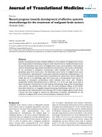
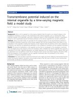
Figure 1 shows FE-SEM images of samples S-15 min
(a), S-30 min (b) and S-50 min (c). The surface film
morphology is smooth in all cases wit h a number of
dots or clusters of dots superimposed on it. These dots/
clusters were not observed in sample S-5 min (not
shown in Figure 1 since its surface was totally feature-
less). In sample S-15 min the surface contains only a
small density of spherical dots, which tend to merge
progressively into clusters of dots as the immersion time
increases (see samples S-30 min (Figure 1b) and S-50
min (Figure 1c)).
TEM images combined with the corresponding dif-
fraction patterns depicted that:
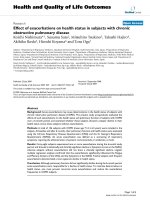
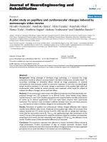
a) The S-5 min film was amorphous and homogeneous
in morphology with a limited surface roughness. The cor-
responding diffraction pattern showed diffuse rings cor-
responding to PtSi. These results are illustra ted in Fi gure
2(a, b). In (a) a bright field image is s hown, while in (b)
the corresponding electron diffraction pattern is
depicted. The rings in the diffraction pattern correspond
to Si and PtSi, while no Pt nanocrystals were detected.
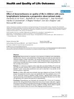
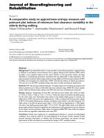
b) The S-15 min sample surface was covered by a
small number of nanocrystals of s izes ranging from 10
to 100 nm and lying on an amorphous layer. The nano-
crystals were iden tified as PtSi nanocrystals, as shown in
the corresponding diffraction pattern and dark field
TEMimagesofFigure3.Figure3ashowsaplaneview
a
b
c
Figure 1 SEM images of the surface of samples S-15 min (a), S- 30 min (b), and S-50 min (c). In (a), the surface is smooth and contains a
small density of spherical nanoparticles on it, while in (b), we reveal that these nanoparticles started to form clusters, which increase in volume
with time (see (c)).
Michelakaki et al. Nanoscale Research Letters 2011, 6:414
/>Page 2 of 6
bright field image, Figure 3b a dark field image and Fig-
ure 3c the cor responding electron diffraction pattern.
Rings from Si (substrate) and PtSi structures are
revealed in the diffraction pattern. The spherical nano-
particles on the surface (images (a) and (b)) are rela-
tively small and well separated between them.
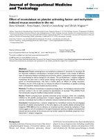
c) The S-30 min sample showed a large number of holes
on an amorhous PtSi film (see bright field TEM image
(Figure 4a) and the corresponding diffraction pattern (Fig-
ure 4)). The holes are probably the footprint of nanocrys-
tals and clusters of nanocrystals, as those identified in the
corresponding SEM images, that were removed during
TEM sample preparation. Their diameter was larger than
the nanoparticles of sample S-15 min.
From the above results it is clear that a PtSi film is
formed on the Si surface during the first minutes of
immersion of the sample i nto the Pt salt used (with an
[HF]/[Pt] ratio of 60). As the immersion time is
increased, PtSi nanocrysta ls start t o form, which merge
progressively into clusters of nanocrystals. The deposi-
tion of Pt on top o f the PtSi layer was observed at
longer immersion times.
Porous anodic alumina template on the galvanically
deposited PtSi layer
Porous anodic alumina (PAA) can be grown on Si by
anodic oxidation of an Al film. In this work, we investi-
gated the formation of a PAA template on top of the
PtSi layer with the objective to use the PtSi layer under-
neath as a catalyst for the formation of Si nanowires
into the alumina pores. We used three of the PtSi films
grown above, namely S-5 min, S-15 nm and S-30 min.
An Al film, 500 nm thick, was deposited on the PtSi/Si
substrate and an Al ohmic contact was formed on the
backside of the wafer. The samples were then anodized
in sulfuric acid aqueous solution at an anodization
Figure 2 Plane-view bright-field image (a) and the corresponding electron diffraction pattern (b) from sample S-5 min. The rings in the
diffraction pattern correspond to Si and PtSi structures. No Pt nanocrystals were detected.
Figure 3 Plane-view bright-field image (a), dark-field image (b), and the corresponding electron diffraction pattern (c) from sample S-
15 min. Rings from Si (substrate) and PtSi structures are revealed in the diffraction pattern. The spherical nanoparticles on the surface (images
(a) and (b)) are relatively small and well separated between them.
Michelakaki et al. Nanoscale Research Letters 2011, 6:414
/>Page 3 of 6
voltage of 20 V. The corresponding current-time anodi-
zation curves, compared to the one obtained without
the PtSi layer, are show n in Figure 5. T he general form
of the c urves is the same as that of the Al/Si anodiza-
tion curve up to the time that the pores reach the
Al
2
O
3
/Si or Al
2
O
3
/PtSi interface. The different phases of
the anodization process are as follows [21]: At the very
beginning of the anodization the current drops sponta-
neously to a lower value due to initiation of the oxida-
tion of the Al surface. It then starts to increase with a
certain rate during the phase of initiation of pore forma-
tion and it almost stabilizes when pore formation is on-
going. This phase continues until the po res reach the
interface with Si and it then drops suddenly to a mini-
mum value. This current decrease corresponds to the
initiation of oxidation of the Si surface underneath the
PAA film [21]. The anodization curve of the sample
PAA/S-5 min followed the same behavior with that
described above, which means that a thin SiO
2
film was
formed underneath the PtSi layer by oxygen diffusion
through the silicide. On the other hand, in the other
two cases of samples PAA/S-15 and PAA/S-30 an
abrupt increase of the current density with time was
observed at the end of Al oxidation. As it will be illu-
strated below in the TEM images, this is due to the fact
that the pore bottom reaches the surface of metal dots
present on the PtSi film in these two last samples and
an important leakage current flows to the Si substrate
through these dots.
Cross sectional TEM images were obtained from two
different samples to illustrate the above results. In the
first case the sample u sed was PAA/S-15 min and the
process was stoppe d before the final current incr ease in
the anodization curve. In the second case the sample
PAA/S-30 min was used and the process continued for
some time after the current increase initiation. The cor-
responding cross sectional TEM image and electron dif-
fraction pattern showed the following behavior:
Sample PAA/S-15 min, end of process before the final
abrupt increase in the anodization current
The corresponding results are shown in Figure 6. In
(a) and (b) we see the cross sectional bright field TEM
images, while in (c) the corresponding electron diffrac-
tion pattern. In panel (a) we reve al the Si substrate
(indicated by 1), a very thin amorphous layer (indicated
by 2) and another layer on top (indicated by 3). Within
this last layer we identify Al nanocrystals (indicated by
(a)) and round shape multi-phase clusters, containing
different phases o f Pt, Al and Si. This mea ns that in this
Figure 4 Plane-view bright-field image (a) and the corresponding electron diffraction pattern (b) from sample S-30 min.SiandPtSi
rings are revealed, while no Pt rings are detected. The nanofeatures on the plane-view image seem to be holes corresponding to the footprint
of nanocrystals that were probably removed during sample preparation. Their diameter is larger than the PtSi nanoparticles observed in sample
S-15 min.
Figure 5 Current-time anodization curves of an Al film on Si
and on different PtSi/Si substrates (samples S-5 min, S-15 min,
and S-30 min). In all cases, the Al film thickness was 500 nm. The
anodization curve of sample Al/S-5 min is quite similar to that of Al/
Si, while in the cases of samples Al/S-15 min and Al/S-30 min the
current increases significantly when the PAA film reaches the
underlying surface.
Michelakaki et al. Nanoscale Research Letters 2011, 6:414
/>Page 4 of 6
Figure 6 Cross-sec tional bright-field TEM images (panels (a), (b)) and the corresponding electron diffraction pattern (panel (c))
(sample PAA/S-15 min/Si). In this sample the anodization was stopped before the abrupt current increase in the anodization current. In panel
(a), we reveal an amorphous layer (indicated by 2) on the Si substrate (indicated by 1). On top of this thin amorphous layer, there is another
layer (layer 3) in which we identify different round-shaped multi-phase clusters of Pt-Al-Si (indicated by b) and Al nanocrystals (indicated by a). In
panel (b), the pores of the PAA film are shown in larger magnification, while the inset illustrates the barrier layer at the bottom of the pores. The
electron diffraction pattern of panel (c) reveals that some of the Al nanocrystals are in very good epitaxial relationship with the Si substrate.
Figure 7 Cross sectional bright field images of sample S-30min with a PAA film on top. In panel (a) the morphology of the interface with
the Si substrate is shown, depicting the presence of large nanograins between the PAA film and Si (attributed to Pt nanograins and illustrated
in higher magnification in the inset of panel (a)). On top of these nanograins the alumina barrier layer usually observed at each pore bottom at
the interface of PAA films with Si (in the absence of Pt in-between) is missing. Panel (b) shows another part of the sample cross section which
illustrates that occasionally a continuous film of crystalline Pt exists between the PAA film and the Si substrate. The white area on the right
depicts either amorphous parts of this film or Pt crystals with different orientation.
Michelakaki et al. Nanoscale Research Letters 2011, 6:414
/>Page 5 of 6
sample the Al film is not fully transformed into Al
2
O
3
,
but some Al nanocrystals still remain. From the electron
diffraction pattern of panel (c) it was revealed that some
of the Al nanocrystals are in very good epitaxial rela-
tionship with the Si substrate. In panel (b) the pores of
the porous anodic alumina (PAA) are shown in larger
magnification, while the inset illustrates the barrier layer
at the bottom of the pores.
Sample PAA/S-30 min, end of the process after the
final abrupt increase in the anodization current
The corresponding results are shown in Figure 7. At
the interface of Pt with Si large nanograins are depicted,
asthoseidentifiedonthesurfaceofsampleS-30min
(see panel a). The barrier layer usual ly observed at each
pore bottom is absent above the nanograin and the
pores seem to reach directly the grain surface. This
explains the appearance of the high leakage current in
the anodization curve, which can be attributed to a
direct current flow from the electrolyte to the Si surface
through the nanograin. The exis tence of the grains pre-
vents the homogeneous oxidation of the Si surface
through the pores at the Al
2
O
3
/Si interface.
Conclusions
The formation of a PAA/PtSi nano-template on Si by
galvanic deposition of Pt, physical vapor deposition of
Al and anodic oxidation of the Al film was investigated
in detail. Depending on the immersion time of the sam-
ples into the Pt salt solution, a thin PtSi layer on Si can
be obtained, on top of which a homogeneous PAA tem-
plate can be formed. This nano-template is very appro-
priate for the growth of ordered Si nanowires within the
pores using the VLS technique catalyzed by the PtSi
nanofilm at the bottom of each pore.
Author details
1
Institute of Microelectronics, NCSR Demokritos, Terma Patriarchou Grigoriou,
Aghia Paraskevi, 153 10, Athens, Greece
2
Solid State Physics Section,
Department of Physics, Aristotle University of Thessaloniki, 54124
Thessaloniki, Greece
Authors’ contributions
IM performed sample preparation, AGN supervised the work and wrote the
paper, ES, AB and NF performed the TEM work.
Competing interests
The authors declare that they have no competing interests.
Received: 27 January 2011 Accepted: 8 June 2011
Published: 8 June 2011
References
1. Najmzadeh M, De Michelis L, Bouvet D, Dobrosz P, Olsen S, Ionescu AM:
“Silicon nanowires with lateral uniaxial tensile stress profiles for high
electron mobility gate-all-around MOSFETs”. Microel Engin 2009, 87(5-
8):1561.
2. Poli S, Pala MG, Poiroux T: “Full Quantum Treatment of Remote Coulomb
Scattering on Remote Silicon Nanowire FETs”. IEEE Trans Electron Devices
2009, 56(6):1191.
3. Coligne J-P, Lee Chi-Woo, Afzalian A, Akhavan ND, Yan R, Ferain I, Razavi P,
O’Neill B, Blake A, White M, Kelleher A-M, Mc Carthy B, Murphy R:
“Nanowire transistors without junctions”. Nature Nanotechnology 2010,
5(3):225-229.
4. Feste SF, Kcoch J, Habicht S, Buca D, Zhao Q-T, Mantl S: “Silicon nanowire
FETs with uniaxial tensile strain”. Solid St Electronics 2009, 53:1257.
5. Boukai AI, Bunimouich Y, Tahir-Kheli J, Yu J-K, Gooldard WA, Health JR:
“Silicon Nanowires as efficient thermoelectric materials”. Nature Lett 2008,
451:168.
6. Fang C, Agarwal A, Widjaja E, Garland MV, Wong SM, Linn L, Khalid NM,
Salim SM, Balasubramanian N: “Metallization of Silicon Nanowires and
SERS Response from a single metallized Nanowire”. Chem Mater 2009,
21:3542.
7. Zianni X, Nassiopoulou AG: “Calculated PL lifetimes of Si nanowires: the
effect of a dispersion in the crystallographic orientations”. Mater Sci Eng
B 2003, 101:242.
8. Elfstrom N, Karlstrom AE, Linnros J: “Silicon Nanoribbons for Electrical
Detection of Biomolecules”. Nano Lett 2008, 8:945.
9. Zervos M, Othonos A: “Synthesis of Tin Nitride Sn
x
N
y
Nanowires by
Chemical Vapour Deposition”. Nanoscale Res Lett 2009, 4:1103.
10. Seo S, Zhao GY, Pavlidis D: “Power characteristics of AlN/GaN MISFETs on
sapphire substrate”. Electron Lett 2008, 44:244.
11. Zervos M, Papageorgiou P, Othonos A: “High yield-low temperature
growth of indium sulphide nanowires via chemical vapor deposition”.
Jour Cryst Growth 2010, 312:656.
12. Baron T, Gordon M, Dhalluin F, Terwon C, Feret P, Gentile P: “Si nanowire
growth and characterization using a microelectronics-compatible
catalyst: PtSi”. Appl Phys Lett 2006, 89:233111.
13. Kokonou M, Nassiopoulou AG, Giannakopoulos KP: “Ultra-thin porous
anodic alumina films with self-ordered cylindrical vertical pores on a p-
type silicon substrate”. Nanotechnology 2005, 16:103.
14. Oide A, Asoh H, Ono S: “Natural Lithography of Si Surfaces Using
Localized Anodization and Subsequent Chemical Etching”. Electroch Solid
State Lett 2005, 8(7):G172.
15. Aso H, Sasaki K, Ono S: “Electrochemical etching of silicon through
anodic porous alumina”. Electroch Commun 2005, 7:953.
16. Zacharatos F, Gianneta V, Nassiopoulou AG: “Highly ordered hexagonally
arranged nanostructures on silicon through a self-assembled silicon-
integrated porous anodic alumina masking layer”. Nanotechnology 2008,
19:495306.
17. Zacharatos F, Gianneta V, Nassiopoulou AG: “Highly ordered hexagonally
arranged sub-200 nm diameter vertical cylindrical pores on p-type Si
using non-lithographic pre-patterning of the Si substrate”. Phys Stat Sol
2009, A206(6):1286.
18. Dayen J-F, Rumyantseva A, Ciornei C, Wade TL, Wegrowe J-E: “Electronic
transport of silicon nanowires grown in porous Al
2
O
3
membrane”. Appl
Phys Lett 2007, 90:173110.
19. Gianneta V, Huffman M, Nassiopoulou AG: “Formation of porous anodic
alumina templates in selected micrometer-sized areas on a Si substrate.
Application for growing ordered Ti nanopillars”. Phys Status Solidi 2009, A
206(6):1309-1312.
20. Cerruti M, Doerk G, Hernandez G, Carraro C, Maboudian R: “Galvanic
Deposition of Pt Clusters on Si: Effect of HF Concentration and
Application as Catalyst for Silicon Nanowire Growth”. Langmuir 2010,
26(10):432.
21. Kokonou M, Nassiopoulou AG, Gainnakopoulos KP, Travlos A, Stoica T,
Kennou S: “Growth and characterization of high density stoichiometric
SiO
2
dot arrays on Si through an anodic porous alumina template”.
Nanotechnology 2006, 17:2146.
doi:10.1186/1556-276X-6-414
Cite this article as: Michelakaki et al.: Porous anodic alumina on
galvanically grown PtSi layer for application in template-assisted Si
nanowire growth. Nanoscale Research Letters 2011 6:414.
Michelakaki et al. Nanoscale Research Letters 2011, 6:414
/>Page 6 of 6