Báo cáo hóa học: " Coherence time-based cooperative MAC protocol 1 for wireless ad hoc networks" doc
Bạn đang xem bản rút gọn của tài liệu. Xem và tải ngay bản đầy đủ của tài liệu tại đây (383.34 KB, 12 trang )
RESEARCH Open Access
Coherence time-based cooperative MAC protocol
1
for wireless ad hoc networks
Murad Khalid
1*
, Yufeng Wang
1
, Ismail Butun
1
, Hyung-jin Kim
2
, In-ho Ra
3
and Ravi Sankar
1
Abstract
In this article, we address the goal of achieving performance gains under heavy-load and fast fading conditions.
CoopMACI protocol proposed in Proceedings of the IEEE International Conference on Communications (ICC), Seoul,
Korea, picks either direct path or relay path based on rate comparison to enhance average throughput and delay
performances. However, CoopMACI performance deteriorates under fading conditions because of lower direct path
or relay path reliability compared to UtdMAC (Agarwal et al. LNCS, 4479, 415-426, 2007). UtdMAC was shown to
perform better than CoopMACI in terms of average throughput and delay performances because of improved
transmission reliability provided by the backup relay path. Although better than CoopMACI, UtdMAC does not fully
benefit from higher throughput relay path (compared to the direct path), since it uses relay path only as a
secondary backup path. In this article, we develop a cooperative MAC protocol (termed as instantaneous relay-
based cooperative MAC–IrcMAC) that uses channel coherence time and estimates signal-to-noise ratio (SNR) of
source-to-relay, relay-to-destination, and source-to-destination links, to reliably choose between relay path or direct
path for enhanced throughput and delay performances. Unique handshaking is used to estimate SNR and single
bit feedbacks resolve contentions among relay nodes, which further provides source node with rate (based on
SNR) information on source-to-destination, source-to-relay, and relay-to-destination links. Simulation results clearly
show that IrcMAC significantly outperforms the existing CoopMACI and the UtdMAC protocols in wireless ad hoc
network. Results show average throughput improvements of 41% and 64% and average delay improvementd of
98.5% and 99.7% compared with UtdMAC and CoopMACI, respectively.
Keywords: IEEE 802.11, medium access control, signal-to-noise ratio, ad hoc network, coherence time, cooperative
communication
Introduction
Ever-increasing demand for higher throughput and
lower delay in wireless ad hoc networks led to an exten-
sive research into newer techniques, algorithms, and
technologies. One such significant contribution is the
notion of “Cooperative Communication” in ad hoc net-
works. Cooperative communication harnesses the broad-
cast nature of the wireless cha nnel and uses spatial
diversity of independent paths to mitigate channel
impairments (mean signal loss and fading), enhances
throughput capacity of the network, and reduces
retransmission latency [1,2]. In cooperat ive communica-
tion paradigm, nodes cooperate with the source and
destination nodes at physical layer and/or MAC layer to
improve throughput, delay, and coverage. Nodes coop-
erating at the physical layer receive packets and combine
them together using different techniques (e.g., linear or
random coding) for transmission to the destination
nodes. Destination node can use multiple copies of the
transmitted packet to decode with high reliability. Coop-
eration at physical layer has led to a specialized field of
network coding [3].
In general, for single hop ad hoc networks cooperative
MAC protocols can be classified into two major cate-
gories: (1) protocols that invoke rel ay node when trans-
mission time via relay path is better than the direct
path, and (2) protocols that invoke the relay node for
backup transmission when direct transmission fails due
to fading or interference. Cooperative communication is
different from multihop communication in the sense
* Correspondence:
1
Department of Electrical Engineering, University of South Florida, Tampa, FL,
USA
Full list of author information is available at the end of the article
Khalid et al. EURASIP Journal on Wireless Communications and Networking 2011, 2011:3
/>© 2011 Khalid et al; licensee Springer. This is an Open Access article distributed under the terms of the Creative Commons Attribution
License ( g/licenses/by/2.0), which permits unrestricted use, distribu tion, a nd reproduction in any medium,
provided the original work is properly cited.
that although source-destination pair can communicate
directly at some rate, but the relay node is still invoked
to achieve enhanced data rate. Nodes cooperating at
MAC level simply relay the received packets for
improved throughput and coverage reliability. Specifi-
cally, MAC leve l cooperation imp roves performance
when source-destination nodes are separated by a dis-
tance that prevents the source node from directly trans-
mitting to the destination node at high data rates. Using
any intermediate node that is appropriately located (and
is willing to cooperate) can allow transmission at higher
data rates compared to the direct transmission.
CoopMACI protocol falls under category one and is
the most suitable for networks with mobile nodes [4,5].
It is based on slight modification of IEEE 802.11 distrib-
uted coordination function (DCF) that benefits from
cooperation between nodes in infrastructure-based wire-
less LAN (WLAN). CoopMACI uses a table-driven
approach. Source node updates table entries by measur-
ing path loss es between the source and the relay nodes.
Path losses allow estimation of possible rates using a
rate look-up table. Further, the achievable rate between
the relay node and the access point (AP) is obtained by
listening to physical layer header transmissions between
the relay and the AP. Once the source node has a
packet to transmit, it co mpares the transmission times
(using the relay table) between direct and indirect (via
relay) transmissions and then picks the path (direct path
or indirect path) that maximizes the rate. However, it is
noted that CoopMACI only uses either direct path or
indirect path for packet transmission based on updated
table. Korakis et al. [6] extended CoopMACI for ad hoc
network environment. It is very similar to CoopMACI
approach, but adds some minor features in data and
control planes. Reference [7] is a category two coopera-
tive MAC protocol that opportunistically invokes the
relay when direct transmission fails (termed as Utd-
MAC). UtdMAC does not invoke any particular relay
which can support higher data rate to the destination,
but assumes that the relay will cooperate if present. Zhu
and Cao [8] propose that rDCF protocol that requires
periodic broadcast of willing list by each node to its
one-hop neighbors. Further, the protocol piggybacks the
data rate information to its request-to-send (RTS) and
clear-to-send (CTS) packets which add more overhead
and requires modifications to the legacy IEEE 802.11
MAC protocol. Zhu and Cao [9] propose infrastructure-
basedrpcfprotocol,whereanodereportstotheAP
with the sensed channel information. The AP then
informs the node about the feasible rate for the relay
through the polling packet.
It was shown in [7] that under Ray leigh fading condi-
tions, UtdMAC protocol outperforms CoopMAC I in
terms of throughput. It is wor th mentioning here that
UtdMAC assumes that nodes have already agreed to
cooperate and so does not consider relay management
overhead when comparing results with the CoopMACI
protocol. Results show that UtdMAC performs better
because it uses diversity of the relay paths for backup
transmissions. On the other hand, CoopMACI picks
either the direct path or the relay path (indirect path)
for reduced transmission time and does not invoke
diversity for backup transmission. Although, the relay
path can provide higher data rate, it is more susceptible
to transmission failure due to independent fading on
source-to-relay and relay-to-destination links. Hence,
the relay path in CoopMACI can provide higher
throughput, but with lower probability of packet success.
In contrast, UtdMAC has higher probability of packet
success due to backup relay path, but provides lower
data rate depending upon source-destination separation.
In essence, both CoopMACI and UtdMAC protocols
lack in providing higher throughput with higher prob-
ability of success under fast fading conditions.
In this article, we develop IrcMAC protocol that mea-
sures signal-to-noise ratio ( SNR) on source-to-destina-
tion, source-to-relay, and relay-to-destination links to
evaluate packet transmission opportun ities through
direct and the candidate relay paths. A relay path
becomes a candidate only when the channel coherence
time is greater than the total transmission time through
the relay path. Once, IrcMAC selects the best candidate
relay path, the packet is then transmitted through the
path (direct or indirect) that incurs minimum transmis-
sion time. In case, no candidate relay path is available,
the IrcMAC protocol transmits directly to the destina-
tion node at the rat e estimated during the handshake
procedure. Protocol details are provided in later
sections.
System Model Preliminaries
We design our cooperative MAC protocol for a single
channel ad hoc network. Channel is assumed to be sym-
metric, so that communication in either direction
experiences the same channel fading. The system con-
sists of source-destination pair separated by distance (d)
with uniformly distributed nodes that can serve as
potential relays. Let us assume that all nodes are at least
within the mutua l communication range when packets
are transmitted at 1 Mbps. All the nodes transmit at
fixed power. The system model for a general cooperative
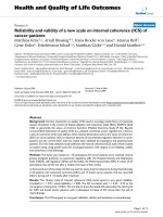
network is shown in Figure 1. Label s S, D, and r
n
repre-
sent, respectively, source, destination, and n
th
relay
node, and SD, Sr
3
, r
3
D represent the source-to-destina-
tion, source-to-relay3, and relay3-to-destination links,
respectively.
In this article, we consider IEEE 802.11 b physical
layer which can support multiple d ata rates of 1, 2, 5.5,
Khalid et al. EURASIP Journal on Wireless Communications and Networking 2011, 2011:3
/>Page 2 of 12
and 11 Mbps [10]. It uses direct sequence spread spec-
trum at a frequency of 2.4 GHz in Industrial, Scientific,
and Medical bands. Different modulations techniques
are used to achieve varying rates. Control packets and
headers (RTS, CTS, PHY, and MAC headers) are trans-
mitted at a fixed rate of 1 Mbps. The achievable instan-
taneous data rated between two nodes depends on the
instantaneous value of the received SNR which is a
function of many factors such as distance, frequency,
propagation environment, mobility, channel fading, and
total noise at the receiver [11]. The received SNR values
at the source and the relay nodes are estimated using
the RTS/CTS messages which are used to estimate cor-
responding rate s (using pre-stored values). Data packets
are transmitted at these rates based on the received
SNR values. The received SNR values remain constant
during the channel coherence time (T
c
is the time dura-
tion in which the channel fade coefficient r emains con-
stant). Further, it is assumed that the channel coherence
time is known at each node based on estimation of
channel Doppler spread (f
D
) statistics (see chapter 3 in
[11]). The inverse relation between T
c
and f
D
is given by
T
c
=
0.423
f
D
. Links (for instance, SD, Sr
3
,andr
3
D in Fig-
ure 1) f
D
experience independent and identically distrib-
uted (i.i.d.) Rayleigh fading.
The proposed protocol
In this section, we provide a brief overview of IEEE
802.11 protocol, explain the IrcMAC protocol, discuss
the network allocation vector (NAV) adaptation and the
framing used in the IrcMAC protocol, and finally
expound on the relay management feature of the
protocol. The proposed protocol is mainly based on
IEEE 802.11 DCF protocol. Appropriate modulation
techniques are chosen to maximize the rate as a func-
tion of SNR.
A. Overview of IEEE 802.11 protocol
Most of the proposed cooperative MAC protocols dis-
cussed in Section “Introduction” follow the basic I EEE
802.11 protocol procedures. In this section, we pro-
vide a brief overview of the IEEE 802.11 DCF protocol.
Readers are referred to [10,12,13], for details. Source
node wishing to transmit probes the channel by sen-
sing it for DIFS (distributed interframe space) dura-
tion. If the channel is sensed idle, then the source
node backs off randomly for a time period that is uni-
formly distributed between 0 and CW (contention
window) and then transmits the RTS packet to the
destination, where, CW duration is contained within
the interval [CW
min
,CW
max
]. The intended receiver
(if not busy) after short interframe space (SIFS) dura-
tion responds by sending a CTS control packet to
acknowledge the channel reservation. This handshake
procedure takes care of two important issues: (1) Sen-
der and receiver establish communication, initialize
parameters , and estimate SNR; (2) the neighboring
nodes that are in communication range of either the
sender or the receiver avoid any transmission initia-
tion during the ongoing session. Neighboring nodes
update their NAV table for no transmission (termed
as mute time) by extracting information from the RTS
or the CTS packet. Once the reservation is completed,
thesourcenodetransmitsthedatapacketafterSIFS
duration and then waits for acknowledgment (ACK)
response from the destination. This completes one
basic transmission cycle with the total duration of
RTS+SIFS+CTS+SIFS+DATA+SIFS+ACK. If the chan-
nel is sensed busy during the DIFS period, then the
source node defers transmission. In case of packet
transmission failure due to fading or collisions, source
node after sensing for DIFS duration backs off for a
random duration that is uniformly distribut ed over the
contention window interval [0, CW
i
], where for the
ith retransmission attempt CW
i
=2
i
CW
min
and CW
i
Î [CW
min
,CW
max
]. This process is known as binary
exponential back-off.
B. The IrcMAC protocol
1) Idle nodes always passively monitor transmissions
in the neighborhood as in [4]. Nodes update the
NAV tables for the duration of transmission. The
data rate (R) is estimated using SNR estimated at the
receiver (source node uses CTS packet, and the relay
nodes use RTS and CTS packets for SNR
estimation).
Figure 1 Cooperative ad hoc network illustration.
Khalid et al. EURASIP Journal on Wireless Communications and Networking 2011, 2011:3
/>Page 3 of 12
2) When the source node has a packet to transmit to
the destination, it senses the channel for idleness. If
the channel remains idle for the DIFS duration, then
the source then backs off for a random duration as
discussed in the Section “Overview of IEEE 802.11
protocol.” Once the backoff counter reaches zero,
the source then sends the RTS packet (at 1 Mbps)
to the destination for channel reservation.
3) If the RTS packet is decoded correctly at the des-
tination node, then it respo nds with the CTS packet
after SIFS duration. The source n ode uses CTS
packet’s reception to estimate the SNR on source-to-
destination link, i.e., SNR
sd
.TheCTSpacketis
transmitted before relays respond so that source and
relays can confirm the presence of the destination
node under fast fading condition. Each available
relay node uses the RTS and the CTS packets recep-
tion to estimate the SNR on the source-to-relay and
the relay-to-destination links, i.e., SNR
sr
and SNR
rd
,
respectively. In IrcMAC prot ocol, relay path is
picked only if the following two conditions are satis-
fied: (1) the sum of total transmiss ion time (i.e., the
time taken by the data packet from the source node
to reach the destination n ode through the relay
node) through the relay node plus the time until the
acknowledgement reception is less than or equal to
the channel coherence time; and (2) the total trans-
mission time through the relay node is less than the
direct path transmission time. In contrast to Coop-
MACI, IrcMAC protocol uses rates (based on esti-
mated SNR) for direct or indirect transmission and,
more importantly, first condition also ensures reli-
able transmission through the relay path. Only the
relay nodes that have their total transmission times
less than the channel coherence time respond in the
relay response frame (RRF) with a single bit feedback
(at1Mbps)toinformthesourcenodeoftheirpre-
sence and the r ate capability. In general, under
heavy load and fast fading conditions, relay nodes’
dynamics necessitate relay information updates in
real time. Furthermore, owing to the presence of
multiple relay nodes, c ollisions are also highly prob-
able. As such, to manage relay contentions and
retrieve rate information, we introduce the RR
frame. The RR frame is an 8-slot frame with 7 bits
per slot. Optimal number of bits per slot can be
investigated, but is not the focus of this research.
However, based on our simulations (for uniform pla-
cement of 500 nodes with varying source-destination
distances from 20 to 120 m) we found 7 bits to be
sufficient for conflict resolution and information
retrieval. It is noted that one conflict-free bit in a
slot is sufficient to tap the relay. Each slot represents
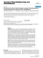
a different rate category as shown in Figure 2. For
instance, the first two slots are for contention
among relays with each relay h aving a combined
rate of 1.4 6 Mbps (
2 × 5.5
2+5.5
, see [4,5] for details).
The only difference between the first two slots is
that the first slot is for relays with source-to-relay
rate of 2 Mbps and relay-to-destination rate of 5
Mbps, whereas, it is reversed in the second slot. The
last slot is for contention among relays such that
each relay satisfies the combined rate requir ement of
5.5 Mbps. In the last slot, since source-to-relay and
relay-to-destination rates are the same, no separate
slot is needed. The dura tion of RR frame is fixed to
about 60 μs. Each relay node remains precisely syn-
chronized after receiving the CTS bits and knows
the start bit time and the last bit time of the RR
frame. A relay node that satisfies the total transmis-
sion time less than the channel coherence time
chooses the appropriate rate slot and then sends a
single bit feedback in a randomly picked bit interval
location. Relays remain idle if they do not meet the
total transmission time req uirement. We assume
that the source node receives a single bit set to 1
when no collision takes place during a specific bit
interval. Each relay node stores its bit interval loca-
tion at which the response was sent to the source
node (e.g., a relay can send one bit feedback at the
54th bit interval location in the rate category slot
(11,11) and store this location).
In the unlikely event, where more than one relay
transmit bits in the same rate slot and same bit
interval location, then the source cannot separate
the relays. Although rare (due to fewer relay nodes
in the same rate slot and relay transmission at ran-
dom bit interval location), this will result in more
than one relay node relaying data packet to the des-
tination node. However, since the conflicting relays
transmit same data at the same rate (i.e., relays
approximately experience same fade) to the destina-
tion node, it does not result in any collision at the
Figure 2 RR frame format.
Khalid et al. EURASIP Journal on Wireless Communications and Networking 2011, 2011:3
/>Page 4 of 12
destination node. Moreover, for the worst case, dis-
tance differences of about 50 m (see range limit in
[4,5]) between the relay nodes transmitting at the
same time and the same rate, the relative packet
delay remains within 0.15 μs at the destination node.
This is much smaller than the packet duration
(which leads to insignificant fade and can be easily
handled by the existing equalizer technology at phy-
sical layer [11]) and, hence, leads to error-free recep-
tion at the destination node.
4) Once the relay responses are received during the
RRframe,thesourcenodesearchesforthebest
relay starting from the (11,11) rate category. The
bestrelayintheRRframeistheonethatoffers
instantaneous combined rate
(R
C
≡
R
Sr
R
rD
R
Sr
+R
rD
)
greater
than the source-destination rate, i.e., R
C
>R
SD
.
5) If the best relay path is fo und, then the source
sends data at the estimated rate of R
Sr
to the relay
for eventual transmission at the rate of R
rD
to the
destination node. After successful data transmission
completion by the relay, ACK is transmitted directly
to the s ource (at 1 Mbps). It is noted that the total
time, from the time when the packet is transmitted
by the source-to-relay node until the reception of
ACK packet at the source node, is less than the
coherence time for reliable transmission through the
relay path. For the 802.11 b rates (1, 2, 5.5, and 11
Mbps) , when the relay path is selected, it finishes its
transmission well within the coherence time of the
channel. An ACK transmission takes about 0.1 ms,
which is also transmitted within the coherence time.
After the successful CTS transmission (at 1 Mbps)
by the destination directly to the source, the channel
remains in the same state because the relay com-
pletes its transmission well within the coherence
time, and thus the transmission of ACK at 1 Mbps
directly to the source is also guaranteed success. If
no ACK is heard from the destination node (due to
increased interferenc e on source-dest ination link),
then the source repeats the transmission cycle by
retrying the fa iled data packet using exponen tial
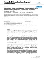
backoff process. The best-relay message sequence is
shown in Figure 3.
6) If no best relay is found with estimated combined
rate better than the source-destination rate, i.e.,
R
sr
i
R
r
i
D
R
sr
i
+ R
r
i
D
R
SD
for ∀i, then the source transmits
the packet directly to the destination node at the
estimate d rate of R
SD
(estimated during RTS/CTS
handshake) as shown in Figure 4. Note that mini-
mum R
SD
is 1 Mbps. In case of no ACK, the source
repeats the transmission cycle by retry ing the failed
data packet using exponential backoff process.
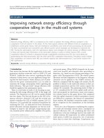
7) In case, no relay feedback is received during the
RR frame (due to collisions or due to absence of
relays) then the source transmits directly to the des-
tination in the same manner as in (6).
8) In case, the relay path is chosen but the relay fails
to receive the packet from the source (due to
increased interference), the source then waits for the
timeout (set to twice the SIFS duration) and then
repeats the transmission cycle.
C. NAV adaptation in IrcMAC protocol
The IEEE 802.11 DCF protocol uses virtual and physical
carrier sensing to schedule transmission. It is assumed
that all the nodes are at least within the mutual commu-
nication range. Source node pre-calculates the transmis-
sion duration based on the packet length and fixed data
rate. The duration fields in the RTS and CTS packets
help the neighbors set their NAV durations (used for
physical and virtual sensing). In c ase of cooperative
communications, the data rate is not fixed and depends
on the relays’ locations and cha nnel conditions. Thus,
RTS
CTS
(1)
(2)
(3)
(3)
(3)
(3)
RR bit
RR bit
RR bit
RR bit
Data
(4)
Relay Data (5)
S
D
Figure 3 Message sequence for the best relay scenario.
RTS
CTS
(1)
(2)
(3)
(3)
(3)
(3)
RR bit
RR bit
RR bit
RR bit
Data
(4)
S
D
Figure 4 Message sequence for no best relay or no RR
scenario.
Khalid et al. EURASIP Journal on Wireless Communications and Networking 2011, 2011:3
/>Page 5 of 12
the RTS and CTS duration fields cannot be precisely set
until relay information becomes available at the source
or the destination node.
In IrcMAC protocol, minimal signaling overhead is
used to announce the transmission rates compared t o
CoopMACI (see [4]). The neighboring nodes in IrcMAC
extract duration information from the RTS, CTS pack-
ets, and from MAC layer headers which are transmitte d
at 1 Mbps. Two points are worth mentioning when ad
hoc network operates under heavy load and fast fading
conditions: (1) A particular relay may not be reachable
due to fading condition or out of coverage range, and
(2) multiple relays transmitting at the same time may
result in contentions and unavailable r ate information.
The RR frame with single-bit feedbacks provides relay
rate information (R
Sr
and R
rD
) and also resolves colli-
sions between the relays. From RR frame, the source
may pick the available best relay for cooperation. Thus,
only after RR frame, the source and the neighbors can
precisely know the data packet transmission’sduration.
As such, this duration information is communicated
through the duration field in the MAC header field.
In IrcMAC protocol, the source sets the duration field
in the RTS to 2SIFS+CTS+RRF (ignore propagation
delay for simplicity). The destination sets the CTS dura-
tion field to
2SIFS + RRF + Data
R
SD
,where
Data
R
SD
is
the duration of data transmission when source transmits
payload data directly to the destination node at the rate
of R
SD
. In IrcMAC protocol, we assume that the neigh-
boring nodes are aware that the duration in the CTS
packet is an estima te, and so the y monitor and extract
information from the MAC header. Although neighbor-
ing nodes can also extract information from the signal
and length fields in the physical header, for IrcMAC, we
use duration field in the MAC header. We, henceforth,
expl ain the N AV update mechanism for IrcMAC proto-
col for the best relay scenario.
When source sends data to the relay n ode, then
neighborswillupdatetheirNAVsto
payload time
R
Sr
+ Data
R
rD
+2SIFS + ACK
by extracting
duration information from the MAC header. The relay
after receiving transmission from the source node will
wait for SIFS duration for eventual transmission to the
destination node. The neighbors detect the transmission
of data packet again from the relay to the destination
node and will extract information from the MAC header
to update their NAVs to
payload time
R
rD
+2SIFS + ACK
. In case of successful
packet transmission, the neighbors will detect the ACK
packet. However, if no ACK is transmitted (due to inter-
ference), then the NAV will expire, and then the neigh-
bors can continue carrier sensing for the DIFS duration
for subsequent transmissions. Figure 5 illustrates NAV
update scheme in the case of the best relay scenario.
D. IrcMAC framing and logical addressing
The IrcMAC protocol uses IEEE 802.11 b physical and
MAC layer frames for unicast transmission as shown in
Figure 6. As discussed above, the PHY and MAC head-
ers are transmitted at 1 Mbps, but the payload can be
transmitted at varying rates of 1, 2, 5.5, and 11 Mbps.
Since MAC header is transmitted at a lower rate of 1
Mbps, and so it can be used by the neighbors to update
the NAV timer. In IrcMAC protocol, multiple relays
contend and respond during RR frame. If each relay
broadcasts its address (to the source node and the desti-
nation node), then it will lead to extensive control over-
head transmission. To avoid this unnecessary overhead
transmission, we use logical addressing in IrcMAC pro-
tocol. We use frame control and Address 4 fields in the
MAC header to invoke one best relay for help. If help
from the available best relay is needed, then the Subtype
field in the frame control is set accordingly for data type
(see [10]). For example, subtype field could be set to
1000 for one best relay and 1111 for no-relay help.
Further, we use first octet of Address 4 to invoke speci -
fic relay as shown in Figure 6. It identifies the best relay
that is invoked for eventual transmission to th e destina-
tion node. The best relay that is picked from the RR
frame has unique bit interval location in the RR frame.
For example, suppose that the best relay that is picked
transmitted one bit at the 52 nd bit interval location.
Thesourcenodechangesthesubtypefieldto1000and
then inserts this unique bit location in the first octet of
the Address 4 field. The contending relays always check
the subtype field and then the first octet of the Address
4 field. Relays then compare the Address 4 field with
the ir stored bit interval locations. If the match is found,
then that relay transmits according to the IrcMAC pro-
tocol. When the best relay tran smits the data packet to
the destination node, it sets the subtype field to 1111, so
that no other relays are invoked.
Node density and relay management
Intuitively, as the node density increases, the probability
of finding relays also increase. This also necessitates
managing relay contentions. UtdMAC assumes that a
node (willing to behave as a relay) will listen passively
and jump in when direct transmission (source-to-desti-
nation) fails. However, it does not address relay rate
requirement and multiple relay transmissions and colli-
sions. Managing relays require overhead which is not
considered in UtdMAC. CoopMACI partially addresses
the relay contention issue by requesting a particular
Khalid et al. EURASIP Journal on Wireless Communications and Networking 2011, 2011:3
/>Page 6 of 12
relay based on the stored relay rates in the table. This
requires addition of three new fields in the RTS packet
in CoopMACI. However, the requested relay may not be
able to provide the required rate because of mobility or
it may not be reachable due to sev ere fading and, there-
fore, CoopMACI may have no option but to transmit
directly. Furthermore, in CoopMACI handshaking, HTS
(Helper-to-Send, see [4]) message is transmitted by the
requested relay to the source before CTS message is
sent by the destination node. Therefore, it is possible
that the destination node may not receive HTS packet
due to fading and begin transmission of CTS packet
while the HTS packet is being received by the source
node. This will lead to unnecessary collisions and waste
precious bandwidth resource.
In contrast, IrcMAC protocol fully exploits availab le
relays and further resolves contention between relays
under fading conditions as follows: (1) all the no des pas-
sively monitor and estimate channel coherence time; (2)
RTS and CTS messages are exchanged before relays can
respond. By this way, only relays that can decode both RTS
and CTS packets respond in the RR frame; (3) each relay
with total transmission time less than the channel coher-
ence time can only respond in RR frame; (4) each rel ay
responds with a single bit at random bit interval location in
an appropriate slot; and (5) source invokes relay with logi-
cal addressing by using Address 4 field in IEEE 802.11
MAC header. In short, IrcMAC resolves possible relay con-
tentions and further guarantees instantaneous rates’ infor-
mation retrieval under fast fading conditions.
Performance evaluation
In this section, saturation throughput and delay perfor-
mances of IrcMAC, CoopMACI, a nd UtdMAC proto-
cols are co mpared and discussed under fast fading
conditions. In the context of this article, saturation
throughput is defined as the successfully transmitted
payload bits per second given that a source node always
has a packet to transmit in its buffer and delay is
defined as the average time taken for successful trans-
mission of a packet. To quantify performance, an event-
based simulator is developed, which precisely follows
802.11 MAC state transitions. For fair comparison, it is
assumedthatUtdMACavoids possible contention
between relay nodes by invoking one best relay node
through RTS packet. On the other hand, CoopMACI
and IrcMAC protocols are capable of handling such
contentions.
Figure 5 Illustration of NAV update mechanism for best relay scenario (note that, for simplicity, RR frame a bove represents fixed
duration for feedback from all Relays).
Khalid et al. EURASIP Journal on Wireless Communications and Networking 2011, 2011:3
/>Page 7 of 12
A. Simulation setup
For fairness, all protocols are compared using the same
simulation setup. The channel is assumed to have flat
Rayleigh fading for the duration of coherence time.
When the channel coherence time is greater than the
total packet transmission time along the path (direct or
indirect), then the estimated SNR is precisely known
along that path (direct or indirect). Further, each pay-
load transmission and each link also experience i.i.d.
fading. The received instantaneous SNR (SNR
jk
)from
node j to node k depends on transmitted power (P
T
),
processing gain (P
g
), distance separation (d), propagation
exponent (2 ≤ b ≤ 6), Rayleigh fading parameter (g),
slow lognormal fading (L), antenna gain product (G
p
),
antenna height effect (h
e
), carrier wavelength (l), and
noise power (N ) as given by [14]
snr
jk
=
P
T
P
g
G
p
h
e
γ
2
10
L
10
λ
2
16π
2
d
β
N
,
(1)
where N = kTBN
f
, k =1.38×10
-23
J/K is Boltzman’s
constant, T = 300 K is the temperature, B =20MHzis
the bandwidth, and N
f
= 10 is the receiver noise factor.
Atthebiterrorrateof10
-5
or better, the rates of 11,
5.5, 2, and 1 Mbps correspond to SNR ranges of snr >
10, 6.25 <snr ≤ 10, 5 <snr ≤ 6.25, and 0.62 ≤ snr ≤ 5,
respectively (adopted from [4,5]). Table 1 shows other
simulation parameters ado pted from IEEE 802.11 b
standard.
Simulation is carried out under saturation condition
such that a source node always has a packet to transmit
in its buffer. Enough relay nodes are placed randomly to
guarantee the relay presence. We evaluate performances
of the protocols (IrcMAC, UtdMAC, and CoopMACI)
under two cases. In the first case, saturation throughput
and delay performances are analyzed as a function of
dis tance for a single source-destination pair. In the sec-
ond case, saturation throughput performance is com-
pared for increasing number of source nodes in the ad
hoc network. All the nodes are randomly placed in a
radius of 200 m. Concurrent transmissions always lead
to collisions. Propagation delay is assumed negligible.
The data collected is averaged over several runs. Each
run uses a different seed value for random placement of
nodes (relays an d sources) and is executed for an
Figure 6 IEEE 802.11 frame format for IrcMAC protocol.
Khalid et al. EURASIP Journal on Wireless Communications and Networking 2011, 2011:3
/>Page 8 of 12
extended period of time (about 1 .5 million packets) to
get stable results. Rayleigh fading is generated using
ITU-R outdoor vehicular multipath model [15] at the
speed of 13 m/s (corresponding to the coherence time
of about 4 ms).
B. Simulation results and discussion
Figure 7 compares saturation throughput as a function
of source-destination distance. For distance range of d ≤
70 m, the source-destination overlapping area is large
and hence encompasses larger number of relay nodes
for transmission. Relays in this range are most likely in
close proximity to both source and the destination
nodes and can offer transmission rates of 11 Mbps or
5.5 Mbps on source-to-relay and relay-to-destination
links. However, in this range on average direct path
transmission rates (of 11 and 5.5 Mbps) are always bet-
ter than the average combined rate through any relay
path
(
11 × 11
22
= 5.5Mbps)
. Therefore, CoopMACI initi-
ates high-rate direct transmission only, whereas Utd-
MAC protocol initiates high-rate direct transmission
using high-rate relay path as a backup path. Thus, in
case of packet failure, UtdMAC relies on high-rate
backup transmission, whereas CoopMACI starts a new
transmission cycle for packet retransmission. We know
that retransmission through a new transmission cycle
requires more time due to DIFS sensing and backoff
interval compared to the backup relay transmission
time. Hence, CoopMACI performs worse than UtdMAC
because of lower transmission reliability (no backup
path) and larger overhead (because of HTS and RTS
packet’s extensions). Our IrcMAC protocol relies on
instantaneous rates available on relay and direct paths.
IrcMAC protocol chooses relay only when it can offer
reliable transmission path by comparing channel coher-
ence time with the instantaneous combined rate through
the relay. Thus, it is possible that although the direct
path rate is better on the average, at the transmission
instant, the direct path may encounter deep fade; how-
ever, the relay path may offer relatively better combined
instantaneous rate. In such a case, IrcMAC protocol will
then pick the relay path for reliable and fast transmis-
sion. As clearly seen from Figure 7, IrcMAC throughput
is significantly better than both UtdMAC and Coop-
MACI in this distance range. Overall saturation
throughput is high in this range for all the protocols.
For distance range of 70 m <d < 100 m, it is observed
that the source-destination overlapping reduces but still
encompasses relays to allow for beneficial relay trans-
mission. Interestingly, in this range, relays offer better
throughput improvement opportunities because of the
combined rates being better than the direct transmission
rates of 1-2 Mbps. These higher combined rates com-
pensate for the overhead time in CoopMACI. Thus,
CoopMACI performs better than UtdMAC (by 0.13
Mbps) at a distance of about 80 m because of improved
throughput through the relay path. In this range, Utd-
MAC initiates direct transmission at the low rate of 1
Mbps. The backup relay also receives information from
the source at this lower rate. In case of direct transmis-
sion failure, backup transmission entails larger transmis-
sion time compared to CoopMACI. In this range,
Table 1 Simulation parameters
Parameter Value Parameter Value
Frequency 2.4 GHz CTS, ACK 112 bits
b 4 Slot time 20 μs
G
p
, h
e
,10
L
10
All set to 1 SIFS 10 μs
l 0.125 m DIFS 50 μs
P
T
0.1 W Payload 1023 bytes
P
G
10 CW
min
32
MAC Header 272 bits CW
max
1024
PHY Header 192 bits Max. trans. attempts 6
RTS 160 bits Rate for MAC, PHY headers, RTS, CTS and ACK packets 1 Mbps
Figure 7 Saturation throughput comparison as a function of
distance.
Khalid et al. EURASIP Journal on Wireless Communications and Networking 2011, 2011:3
/>Page 9 of 12
IrcMAC again performs considerably better than both
the protocols because of reliable instantaneous rate
transmission.
For the distance range of d ≥ 100 m, it is observed
that owing to increased distance and fast fading, direct
transmission throughput is reduced below 1 Mbps.
Furthermore, owing to minimal overlapping and
increased distances between relays, source, and destina-
tion nodes, the average achievable rates on source-to-
relay and relay-to-destinatio n links are also reduced sig-
nificantly. Thus, as expected, the overall throughput is
reduced for all the protocols (see Figure 7). UtdMAC
transmission’s failure rate increases as the source-to-des-
tination distance increases from 100 to 120 m. Backup
relay transmission is also at lower rate (due to increased
distance between relay and destination node). Thus,
UtdMAC saturation throughput reduces from 0.81
Mbps to 5 kbps for distances from 100 to 120 m,
respectively. CoopMACI throughput remains lower than
UtdMAC, because for success through the relay path,
both source-to-relay and relay-to-destination links have
to be in non-fading states at the transmitted rates. In
contrast, IrcMAC outperforms UtdMAC and Coop-
MACI protocols because it makes use of instantaneous
rates that can reliably provide higher throughput. The
saturation throughput for IrcMAC reduces from 1.55
Mbps to 0.97 Mbps for distances from 100 m to 120 m,
respectively.
Figure 8 shows the delay comparison as a function of
distance. Clearly, the del ay of our protocol is lower than
UtdMAC and CoopMACI. At the distance of 100 m,
the delay difference (T
utd,coop
- T
Ircmac
) is 4.71 and 6.44
ms with respect to UtdMAC and CoopMACI, respec-
tively. At the distance of 120 m, this time difference sig-
nificantly increases to 1.63 and 8.18 s with respect to
UtdMAC and CoopMACI, respectively. This is because
of the reliable transmission at high er instantaneous rate
tha t decreases the average transmission time and allows
more packets to be transmitted within the given time
duration. It is noted that the mean delay over the dis-
tance range of 20 m ≤ d ≤ 120 m is 0.28 s, 1.37 s, and
4.07 ms for UtdMAC, CoopMACI, and IrcMAC,
respectively.
Figure 9 compares the saturation throughput as a
function of increasing number of transmitting nodes.
The saturation throughput initially in creases as the
number of transmitting nodes increase. Then, it remains
almost flat up to 15 nodes and then, a slight decline in
throughput is observed. The reason for the decrease in
throughput is because the collisions along with fast fad-
ing become dominant effects and begin to offset the
throughput improvement because of cooperation. How-
ever, it is worth mentioning that compared to non-
cooperative protocols, cooperative protocols will always
scale well with the number of nodes because of reduced
transmission time and increased number of transmis-
sions in a given time period. The mean throughput dif-
ferences of 1.08 and 0.78 Mbps are observed with
respect to CoopMACI and UtdMAC, respectively.
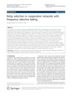
C. Impact of coherence time on performance
In this subsection, we discuss the impact of the
increased mobility on the performance of IrcMAC pro-
tocol as a fun ction of so urce-destination distanc e
separation. We compare with the worst case speed of 27
m/s (corresponding to coherence time of ~ 2 ms), since
we do not foresee larger speed to be of any practical
relevance. As mentioned above, only relays with total
transmission times less than the channel coherence time
transmit single bit feedbacks during the RR frame.
Hence, a relay path is chosen only when it can offer reli-
able transmission path and incurs lesser transmission
time compared to the direct transmission time. In case
of increased mobility, quite intuitively, the average
Figure 8 Average delay for successful packet transmission. Figure 9 Network saturation throughput.
Khalid et al. EURASIP Journal on Wireless Communications and Networking 2011, 2011:3
/>Page 10 of 12
channel coherence time is reduced and, consequently,
we expect lesser number of relays to respond during the
RR frame. In particular, at increased source-destination
distance separations, we expect the likelihood of relays
responding during the RR frame to decrease. Further, at
increased speeds, the estimated SNR (and the corre-
sponding estimated rate) during the RTS/CTS exchange
may differ from the actual SNR (and the achievable
rate) during payload transmission. Intuitively, we expect
reducedthroughputatthespeedof27m/sbecauseof
reduced coherence time and the consequent difference
between estimated SNR and the actual SNR during pay-
load transmission. In Figure 10, we observe that Irc-
MACat13and27m/shaslowerthroughput
differences at distance ranges of d <60mandd >100
m. This is because, for distance range of d < 60 m,
direct path on average offers higher transmission rate
compared with the combined rate through the relay
path, and the SNR estimate is fairly accurate at both
speeds. On the other hand, for distance range of d >
100m,weobserveadecreaseinthenumberofrelays
(because of decreased source-destination overlap), and
further, the likelihood of transmission t ime through the
relay being lesser than the coherence time is also
reduced. Hence, direct transmiss ions are again frequent,
but with increased inaccuracy of SNR estimates (and
corresponding rates) at both speeds. In the range of 60
m ≤ d ≤ 100 m, IrcMAC at 13 m/s performs better than
at 27 m/s because of the increased likelihood of relay
paths with transmission times better than the channel
coherence time. Thus, in the range of 60 m ≤ d ≤ 100
m, reliable relay path transmissions occur more often at
13 m/s. It is noted that the throughput gain for IrcMAC
at 13 m/s is 41% and 64% with respect to UtdMAC and
CoopMACI, whereas at 27 m/s the gain reduc es to 20%
and 39%, respectively.
Conclusion
In this article, we have proposed a novel cooperative
protocol termed as IrcMAC for ad hoc networks. In
contrast to UtdMAC and CoopMACI protocols, Irc-
MAC protocol monitors instantaneous SNR during
handshake procedure and picks a relay path only when
it incurs total transmission time (based on SNR) less
than the channel coherence time and the direct path
transmission time. Thus, the relay is tapped only when
it can offer reliable transmission path; otherwise, direct
transmission takes place. Furthermore, given that all the
nodes are at least within the mutual communication
range, the proposed protocol introduces RR frame that
resolves contentions among candidate relay nodes and
allows contending relays located in close proximity at
the time to communicate instantaneous rate information
to the source node through single-bit feedbacks. Simula-
tion results show average throughput improvement of
41% and 64% and average delay improvement of 98.5%
and 99.7% compared to UtdMAC and CoopMACI pro-
tocols, respectively. In future, we plan to evaluate all the
scenarios beyond nodes in mutual communication
range.
Abbreviations
AP: access point; CTS: clear-to-send; DCF: distributed coordination function;
NAV: network allocation vector; RRF: relay response frame; RTS: request-to-
send; SIFS: short interframe space; SNR: signal-to-noise ratio; WLAN: wireless
LAN.
Acknowledgements
This study was supported in part by the Basic Research Program through
the National Research Foundation of Korea (NRF) funded by the Ministry of
Education, Science and Technology (KRF-2008-314-D00347 and 2010-
0015851).
Author details
1
Department of Electrical Engineering, University of South Florida, Tampa, FL,
USA
2
Chonbuk National University Department of IT Applied System
Engineering, Korea
3
Department of Telecommunication Engineering, Kunsan
National University, Korea
Competing interests
The authors declare that they have no competing interests.
Received: 15 November 2010 Accepted: 6 June 2011
Published: 6 June 2011
References
1. J Laneman, G Wornell, D Tse, An efficient protocol for realizing cooperative
diversity in wireless networks. Proc IEEE ISIT, USA. 294 (2001)
2. A Sendonaris, E Erkip, B Aazhang, User cooperation diversity part I: system
description. IEEE Trans Commun. 51(11):1927–1938 (2003). doi:10.1109/
TCOMM.2003.818096
3. T Ho, DS Lun, Network Coding: An Introduction. (Cambridge University
Press, Cambridge, UK, 2008)
4. P Liu, Z Tao, S Panwar, A co-operative MAC protocol for wireless local area
networks. Proc IEEE International Conference on Communications (ICC)
Seoul, Korea. 2962–2968 (2005)
5. P Liu, Z Tao, S Narayanan, T Korakis, S Panwar, CoopMAC: a cooperative
MAC for wireless LANs. IEEE J Sel Areas Commun. 25(2):340–354 (2007)
Figure 10 Impact of coherence time on saturation throughput.
Khalid et al. EURASIP Journal on Wireless Communications and Networking 2011, 2011:3
/>Page 11 of 12
6. T Korakis, Z Tao, Y Slutskiy, S Panwar, A cooperative MAC protocol for ad
hoc networks. IEEE Pervasive Computing and Communications Workshop
(PerComW), USA. (2007)
7. N Agarwal, D ChanneGowda, L Kannan, M Tacca, A Fumagalli, IEEE 802.11 b
cooperative protocols: a performance study. LNCS. 4479, 415–426 (2007)
8. H Zhu, G Cao, rDCF: a relay-enabled medium access control protocol for
wireless ad hoc networks. IEEE Trans Mobile Comput. 5(9):1201–1214 (2006)
9. H Zhu, G Cao, On improving the performance of IEEE 802.11 with relay-
enabled PCF. ACM/Kluwer Mobile Netw Appl (MONET). 9, 423–434 (2004)
10. IEEE Std. 802.11 b-1999, Part 11:wireless LAN medium access control (MAC)
and physical layer (PHY) specifications: high-speed physical layer extension
in the 2.4 GHz band. (1999)
11. A Goldsmith, Wireless Communications. (Cambridge University Press, 2006)
12. G Bianchi, Performance analysis of the IEEE 802.11 distributed coordination
function. IEEE J Sel Areas Commun. 18(3):535–547 (2000). doi:10.1109/
49.840210
13. K Fakih, J Diouris, G Andrieux, Beamforming in ad hoc networks: MAC
design and performance modeling. EURASIP J Wirel Commun Netw.
2009(839421):1–15 (2009)
14. T Rappaport, Wireless Communications Principles and Practices, 2nd edn.
(Prentice Hall Communications, 2002)
15. Recommendation ITU-R M.1225. />(2009)
doi:10.1186/1687-1499-2011-3
Cite this article as: Khalid et al.: Coherence time-based cooperative MAC
protocol
1
for wireless ad hoc networks. EURASIP Journal on Wireless
Communications and Networking 2011 2011:3.
Submit your manuscript to a
journal and benefi t from:
7 Convenient online submission
7 Rigorous peer review
7 Immediate publication on acceptance
7 Open access: articles freely available online
7 High visibility within the fi eld
7 Retaining the copyright to your article
Submit your next manuscript at 7 springeropen.com
Khalid et al. EURASIP Journal on Wireless Communications and Networking 2011, 2011:3
/>Page 12 of 12